Hans Turck and KG TN902-Q120L130 UHF RFID read/write device User Manual Installation of the BLident UHF Systems
Hans Turck GmbH & Co. KG UHF RFID read/write device Installation of the BLident UHF Systems
Contents
- 1. Annex User Manual
- 2. User Manual
User Manual
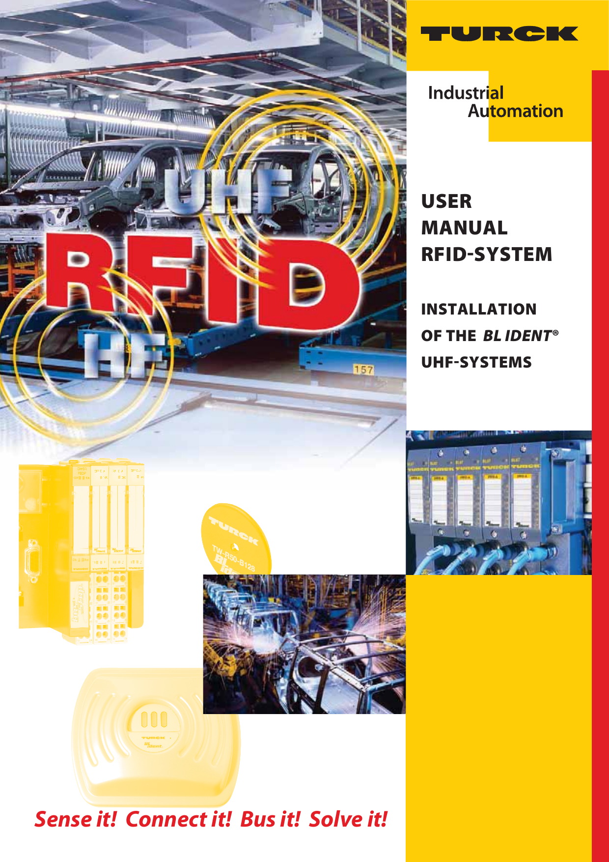
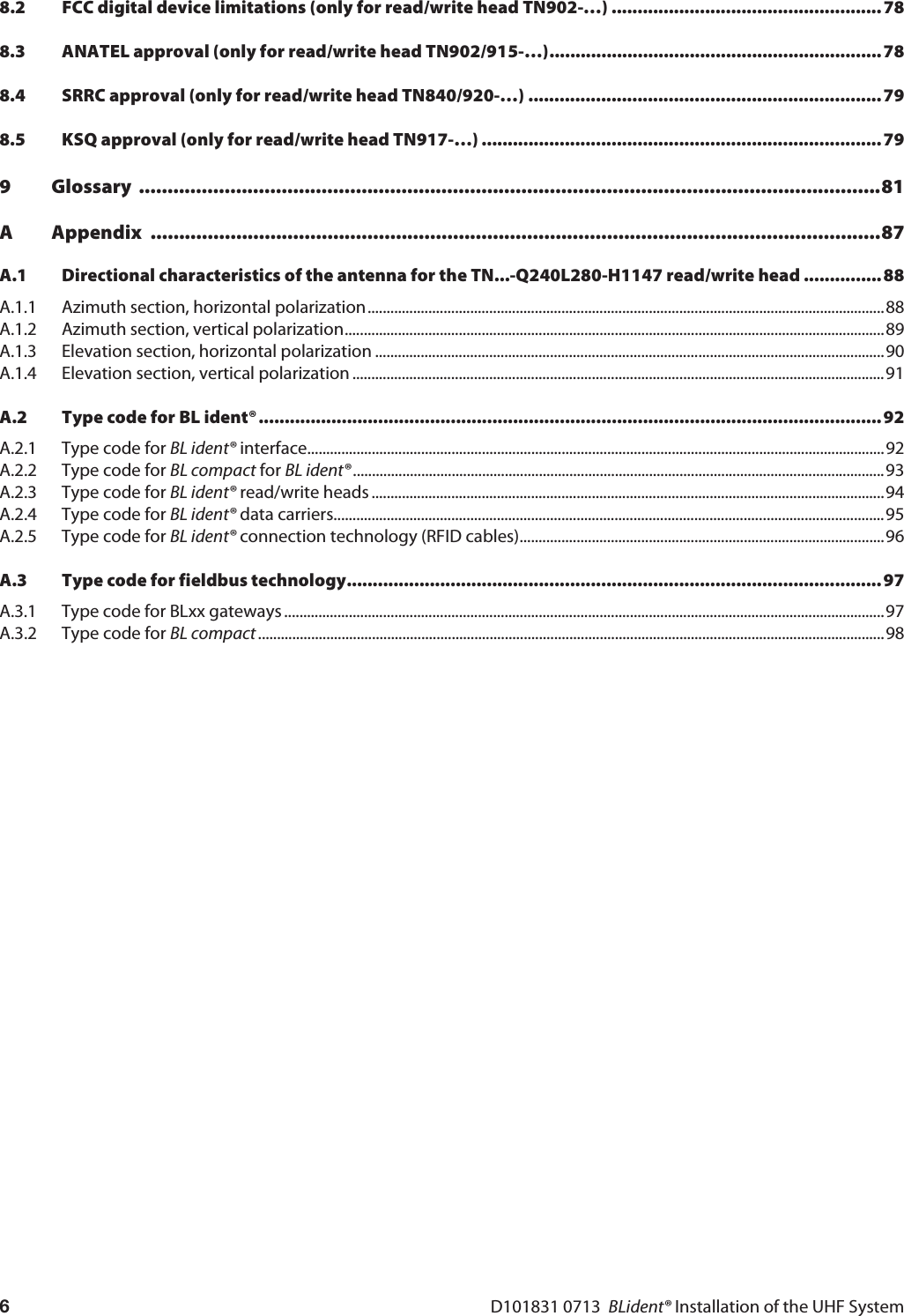


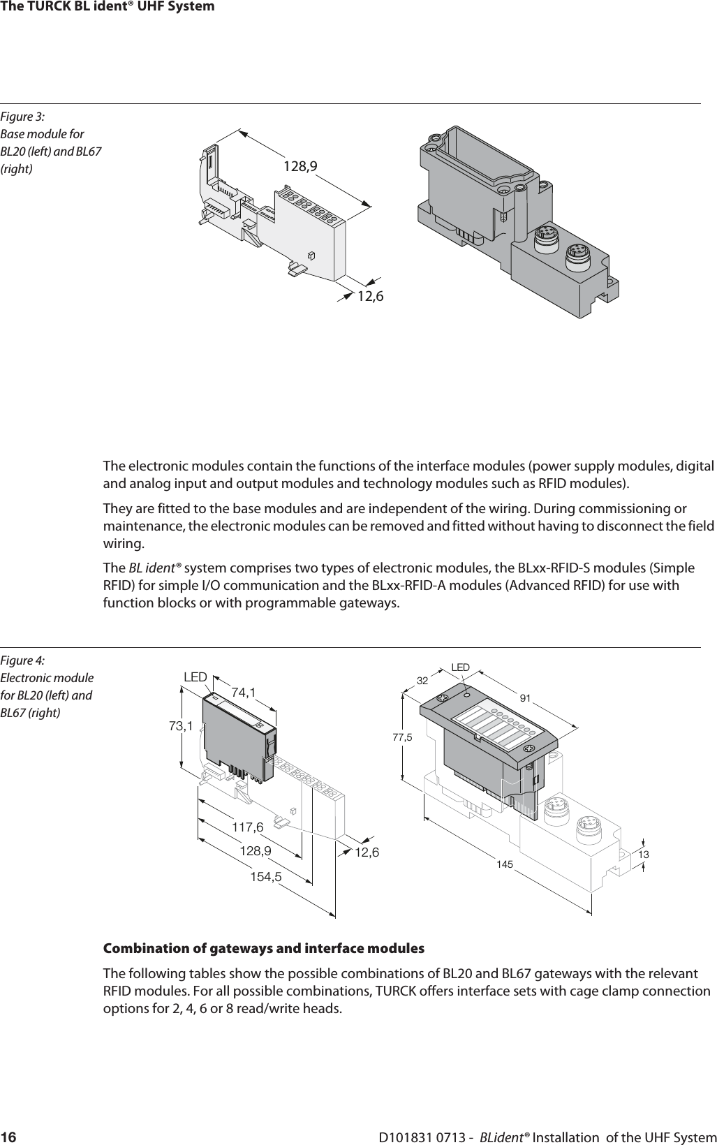
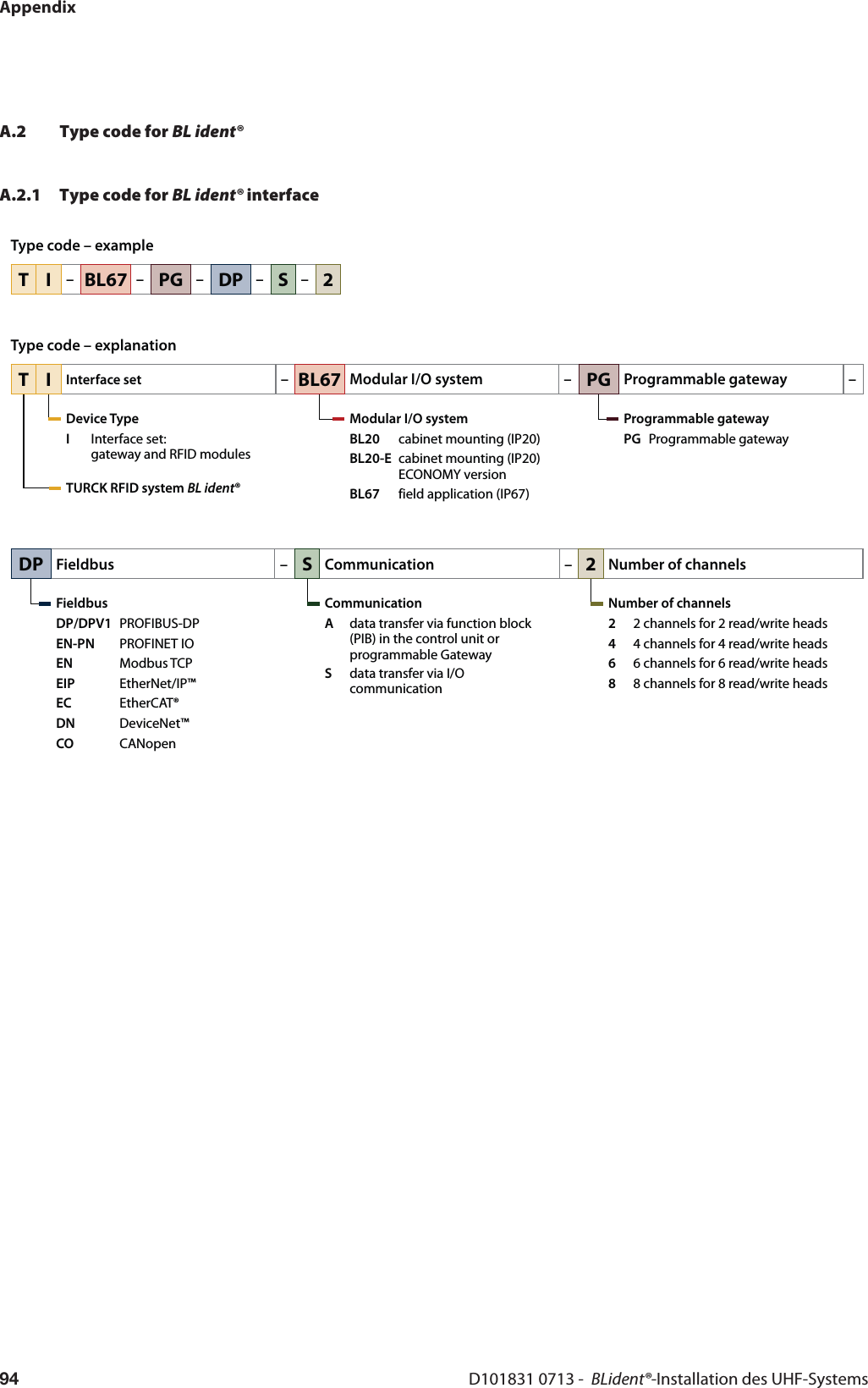
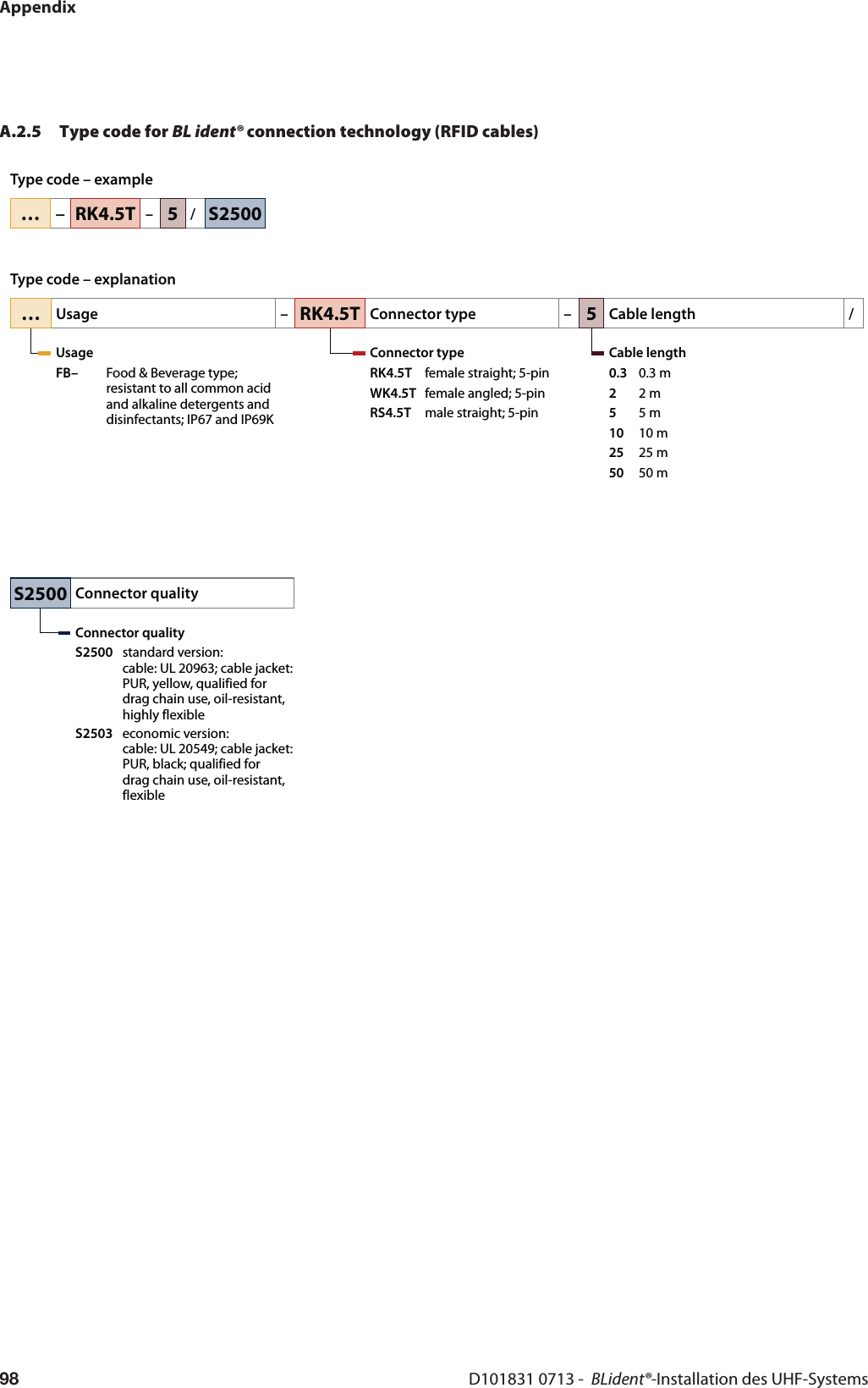
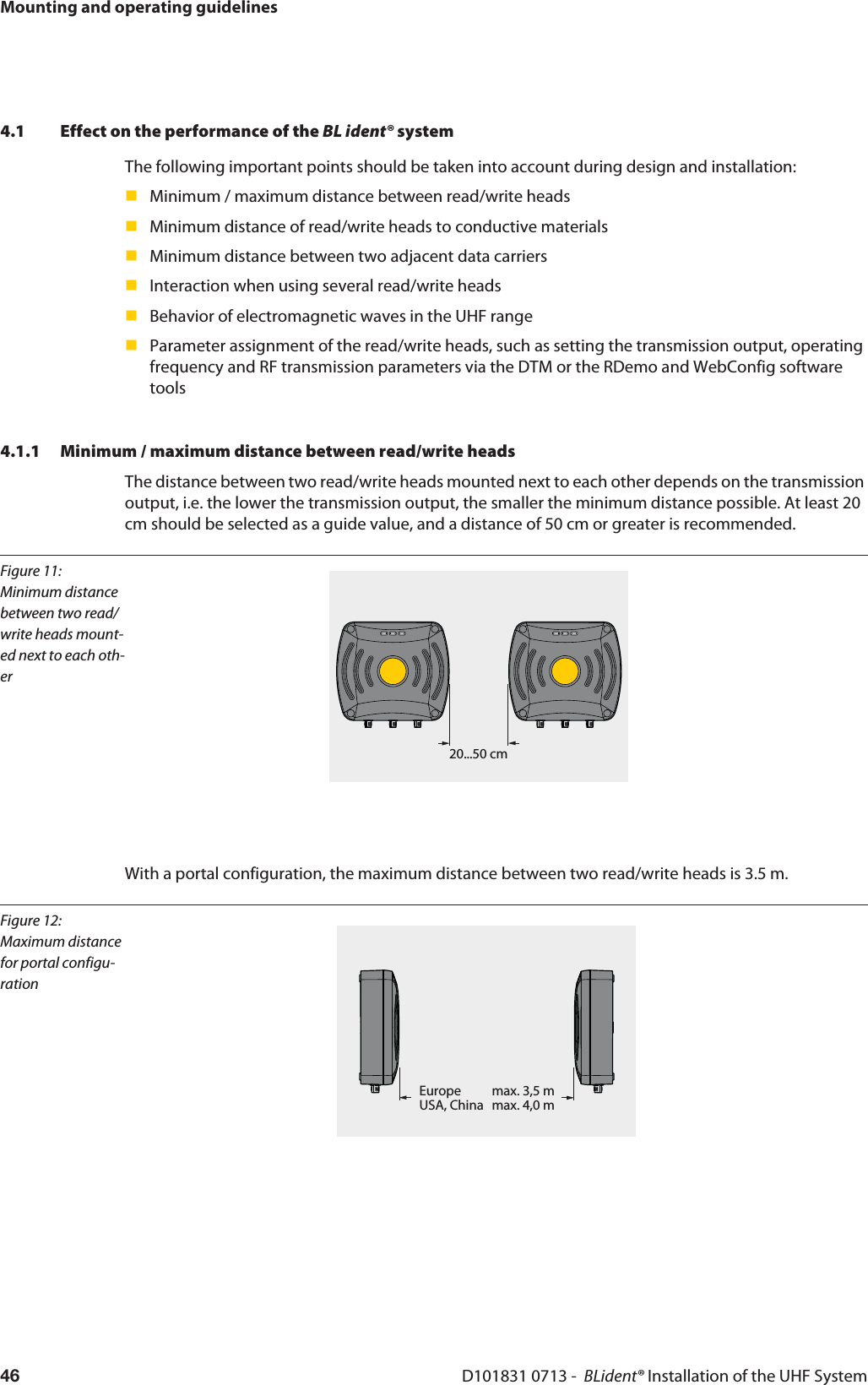
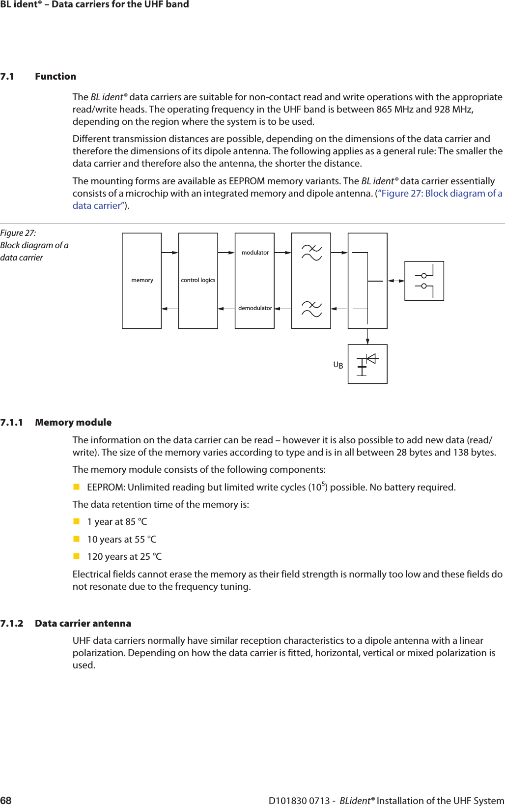
![Figure 7: UHF data carrier memory hierarchyBank 11Bank 10Bank 01Bank 00MSB LSBMSB LSBMSB LSBMSB LSB00hex 0Fhex10hex 1Fhex00hex 0Fhex220hex 22Fhex210hex 21Fhex20hex 2Fhex10hex 1Fhex00hex 0Fhex30hex 3Fhex20hex 2Fhex10hex 1Fhex00hex 0Fhex...Optional XPC_W2 [15:0]Optional XPC_W2 [15:0]...EPC/UII/... [15:0]...EPC/UII/... [N:N-15]PC [15:0]CRC [15:0]...Word 0 of Block 0...TID [15:0]TID [31:16]...Access Passwd [15:0]Access Passwd [31:16]Kill Passwd [15:0]Kill Passwd [31:16]UserTIDEPC/UII/...ReservedThe TURCK BL ident® UHF SystemD101831 0713 - BLident® Installation of the UHF System26BL ident® UHF data carriers are currently available with the following memory types:EEPROM-U-Code G2EEPROM-MonzaEEPROM-HiggsNoteThe number of areas for the different memory types currently varies. The Impinj Monza® 5 therefore only has three areas (the user area is missing), whilst the NXP-G2XM contains all four areas.2.7.1 Multiple access (multi-tag detection, bulk reading)The data carriers are identified in the BL ident® system by means of the UII. With multi-access these must be different! (multiple access means a read/write head can communicate with different data carriers at the same time. The read/write head can thus address a data carrier selectively by means of its UII.)If the data carriers are factory set with the same UII, these must be individually written with different UIIs before they are used for the first time in applications with multi-access.](https://usermanual.wiki/Hans-Turck-and-KG/TN902-Q120L130.User-Manual/User-Guide-2419793-Page-26.png)
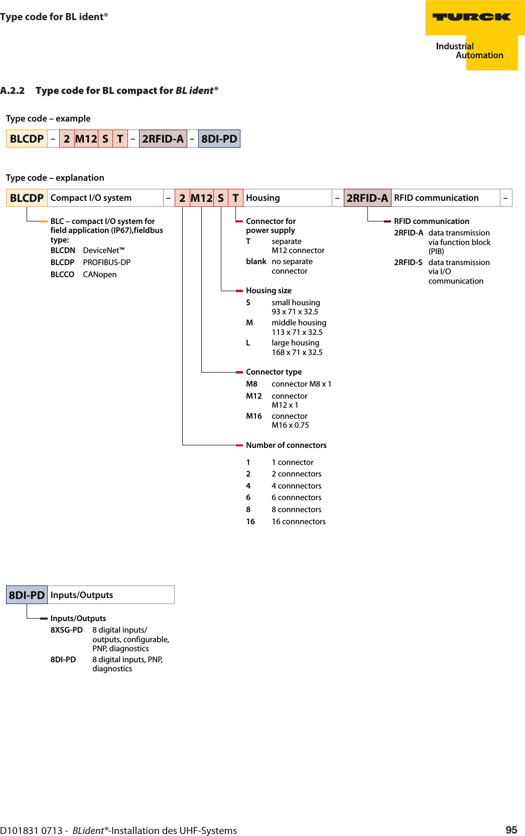
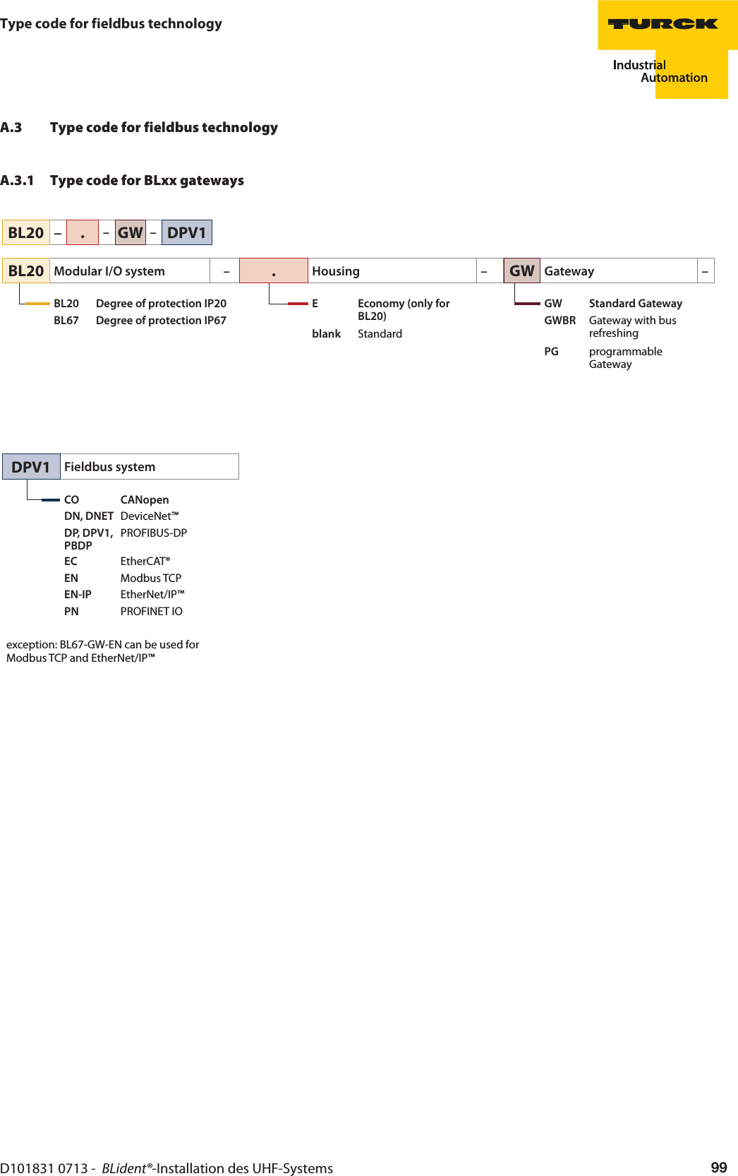
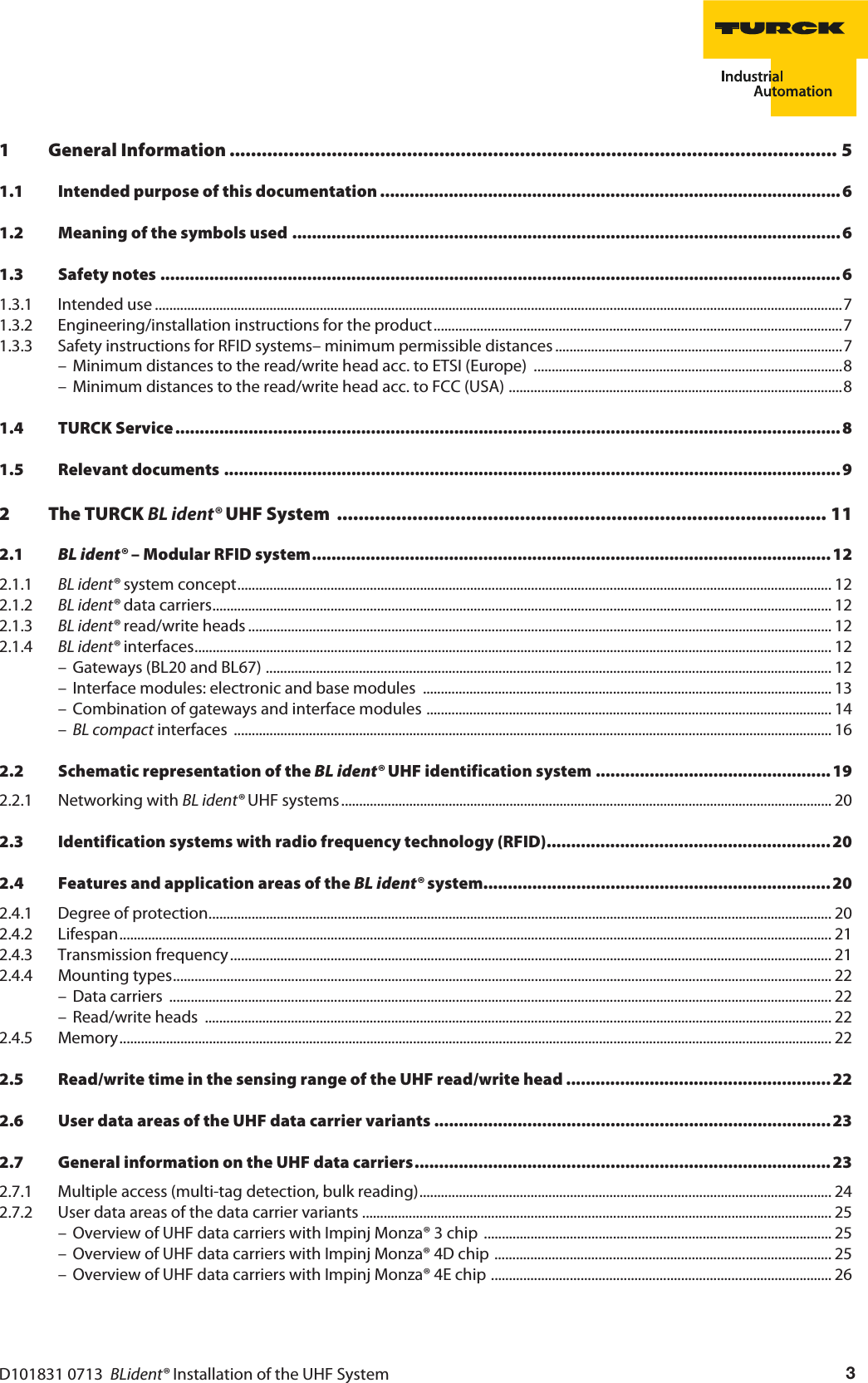
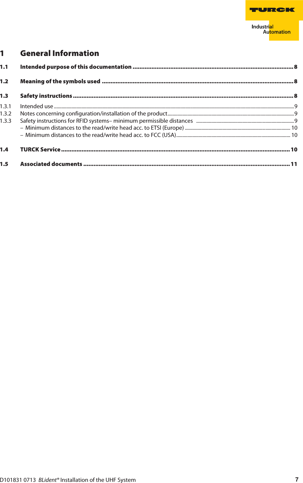
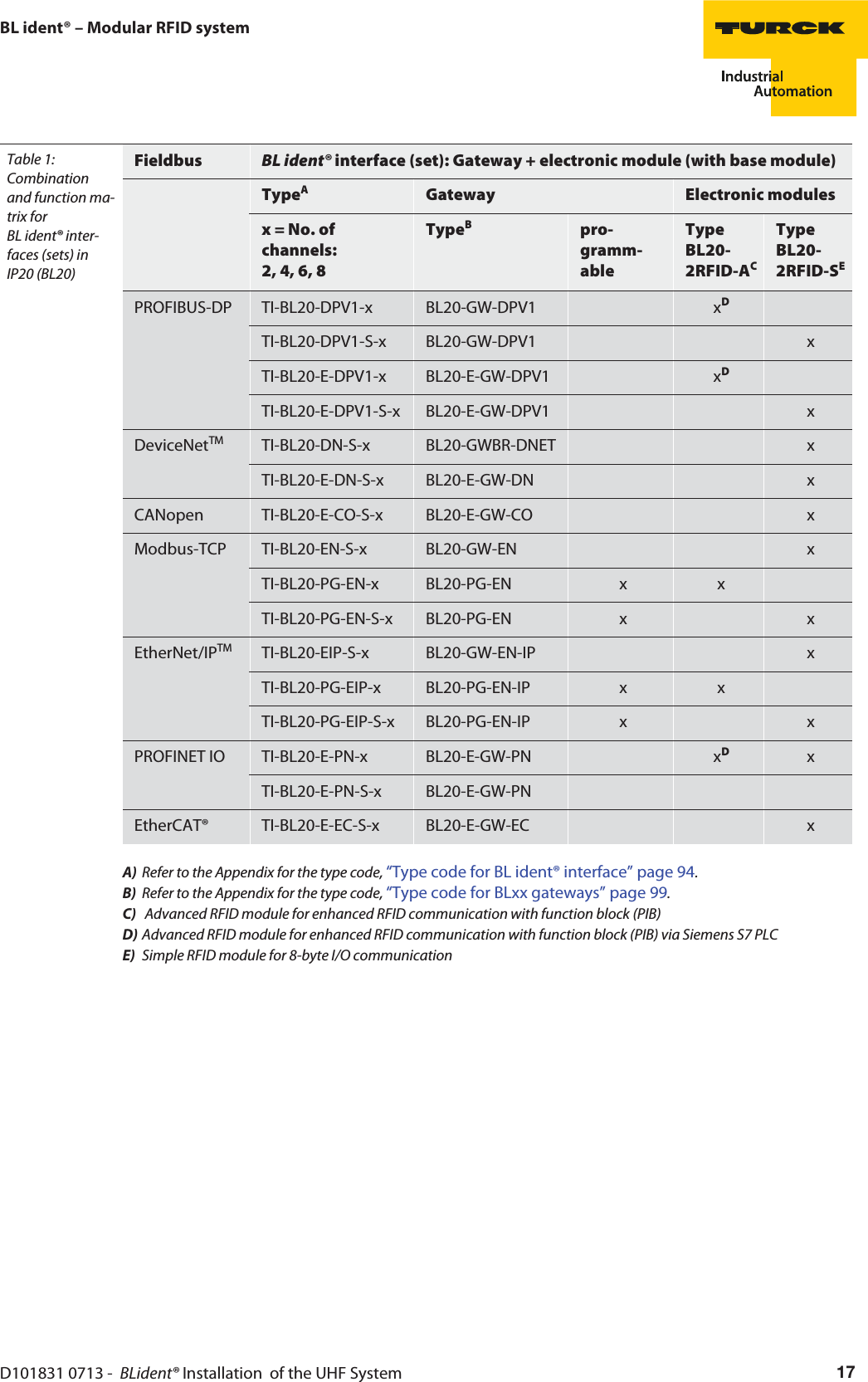
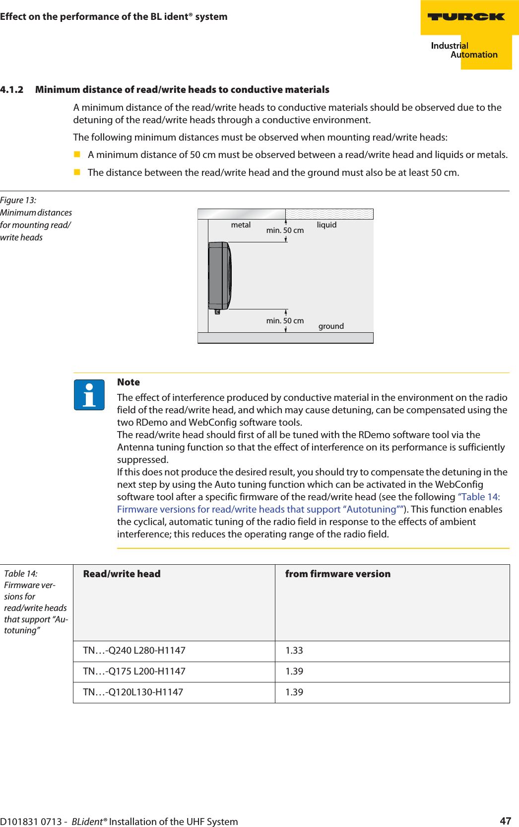
![D101831 0713 - BLident® Installation of the UHF System 27General information on the UHF data carriers2.7.2 User data areas of the data carrier variantsOverview of UHF data carriers with Impinj Monza® 3 chipThe type Impinj Monza® 3 UHF data carriers are provided with a UII memory area of 12 bytes.The following table describes the data structure of the data carriers.Table 4: Memory area of Impinj Monza® 3Bank address[bin.]Bank nameMemory address[hex.]No. of bytesRemark10 TID 10hex-1Fhex 2 0001 + Model number00hex-0Fhex 2 fixed = 111000100000000001 UII 20hex-7Fhex 12 UII10hex-1Fhex 2 Protocol control bits00hex-0Fhex 2 Checksum CRC-1600 Reserved 20hex-3Fhex 4 Password for memory access00hex-1Fhex 4 Password to deactivate the memoryOverview of UHF data carriers with Impinj Monza® 4D chipThe type Impinj Monza® 4D UHF data carriers are provided with a UII memory area of 16 bytes.The following table describes the data structure of the data carriers.Table 5: Memory area of Impinj Monza® 4DBank address[bin.]Bank nameMemory address[hex.]No. of bytesRemark11 User 00hex-1Fhex 4 freely usable10 TID 30hex-5Fhex 6 Serial number20hex-2Fhex 2 Extended TID header10hex-1Fhex 2 Manufacturer ID + model number00hex-0Fhex 2 11100010 + manufacturer ID01 UII 20hex-9Fhex 16 UII10hex-1Fhex 2 Protocol control bits00hex-0Fhex 2 Checksum CRC-1600 Reserved 20hex-3Fhex 4 Password for memory access00hex-1Fhex 4 Password to deactivate the memory](https://usermanual.wiki/Hans-Turck-and-KG/TN902-Q120L130.User-Manual/User-Guide-2419793-Page-27.png)
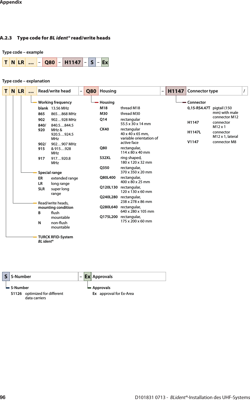
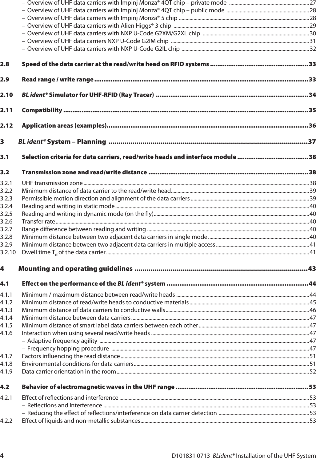
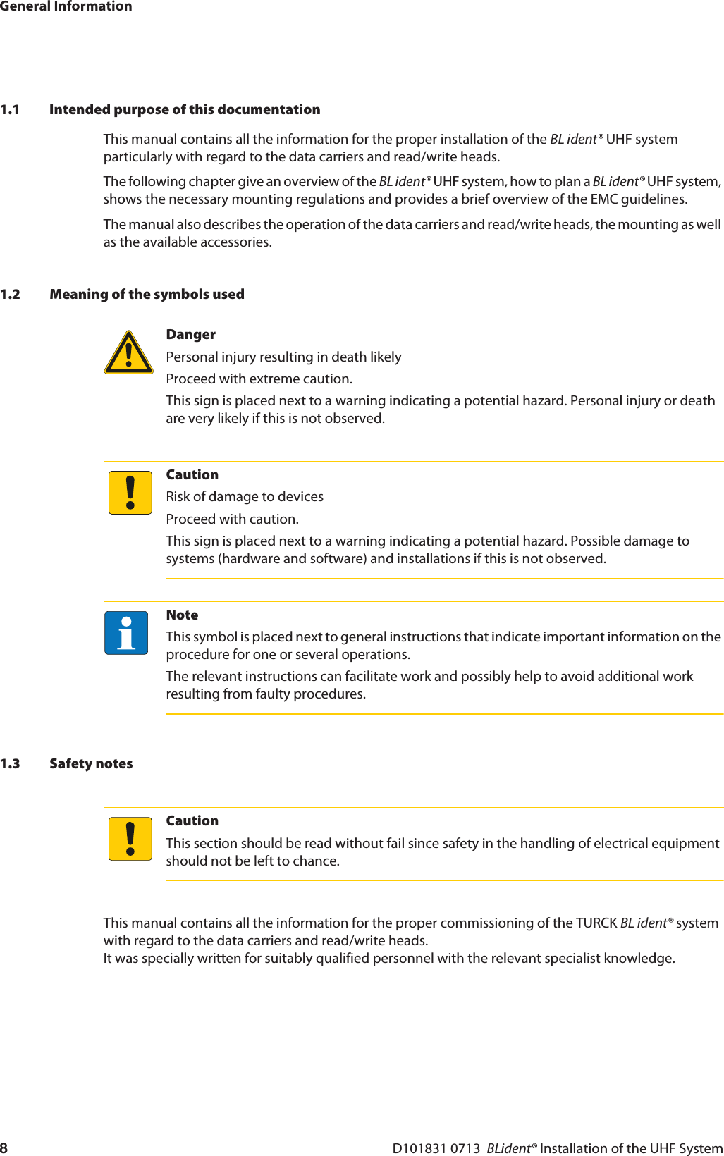
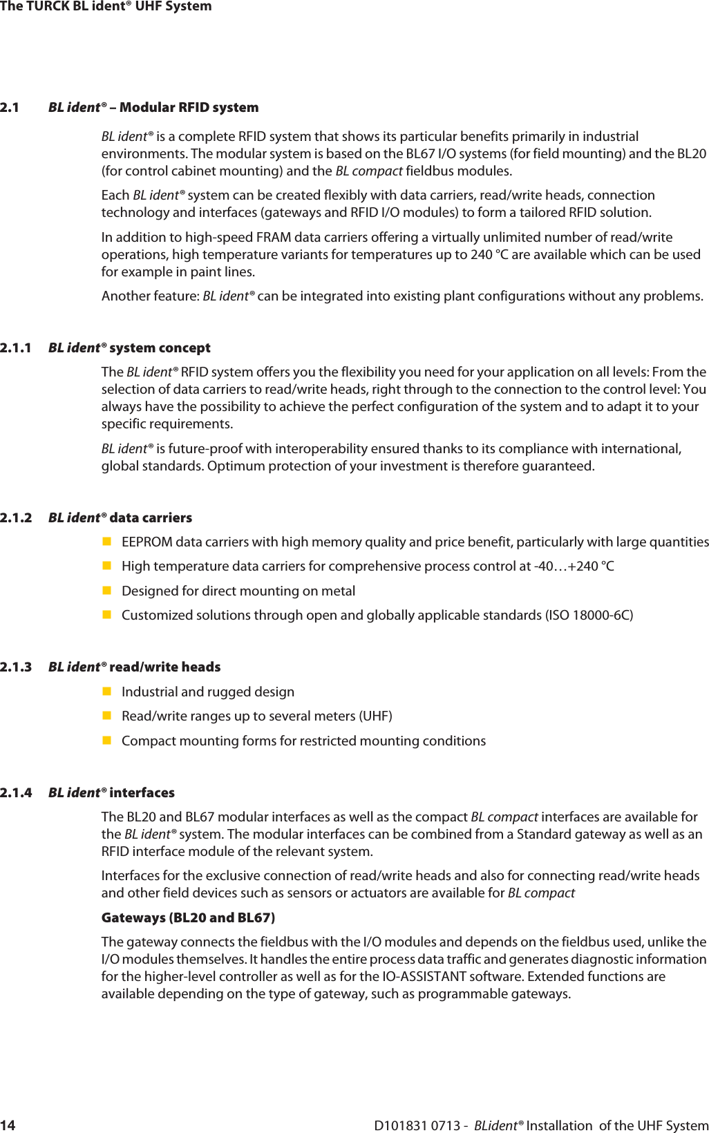
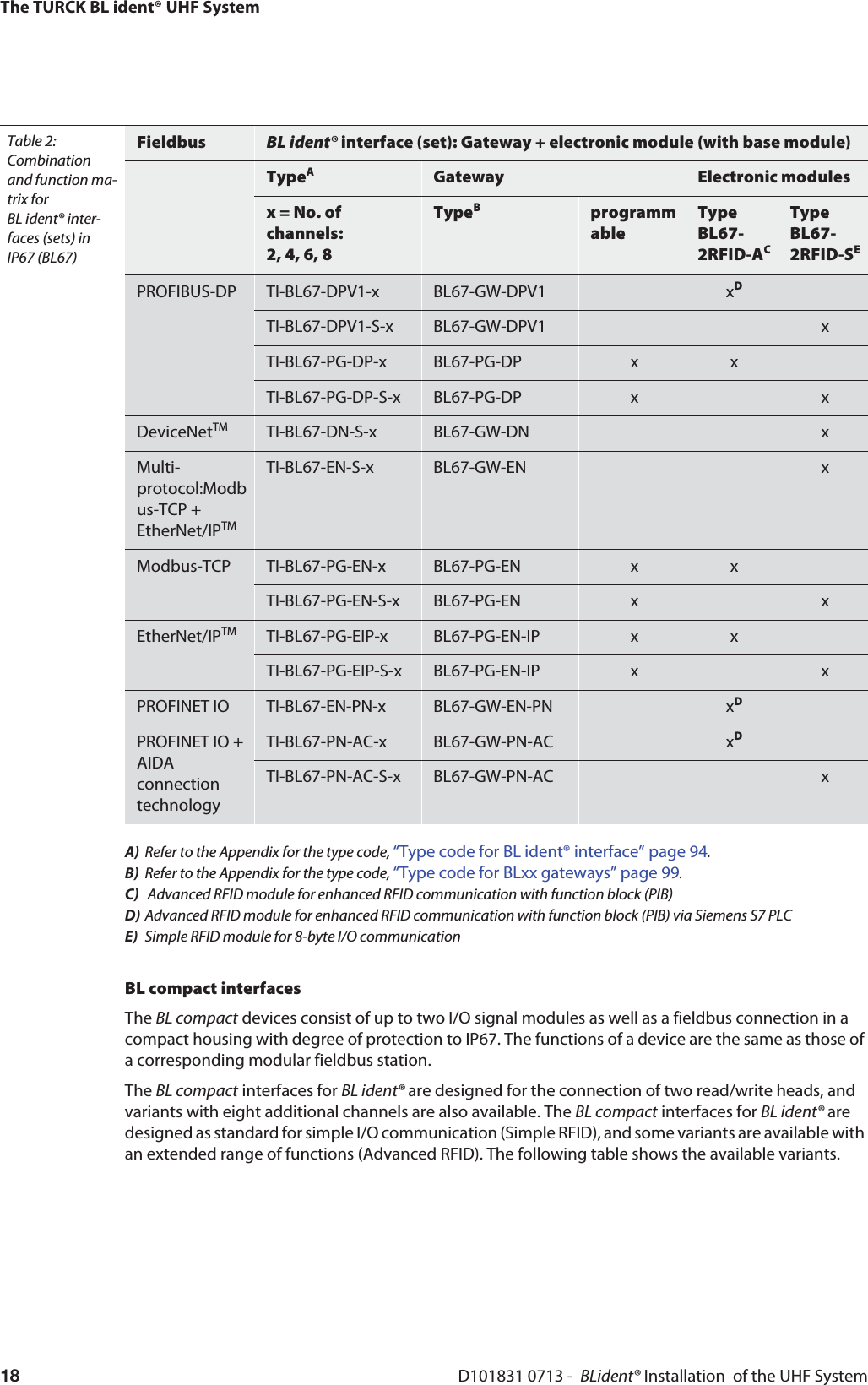
![The TURCK BL ident® UHF SystemD101831 0713 - BLident® Installation of the UHF System28Overview of UHF data carriers with Impinj Monza® 4E chipThe type Impinj Monza® 4E UHF data carriers are provided with a UII memory area of 62 bytes.The following table describes the data structure of the data carriers.Table 6: Memory area of Impinj Monza® 4EBank address[bin.]Bank nameMemory address[hex.]No. of bytesRemark11 User 00hex-7Fhex 16 freely usable10 TID 30hex-5Fhex 6 Serial number20hex-2Fhex 2 Extended TID header10hex-1Fhex 2 Manufacturer ID + model number00hex-0Fhex 2 11100010 + manufacturer ID01 UII 20hex-20Fhex 62 UII10hex-1Fhex 2 Protocol control bits00hex-0Fhex 2 Checksum CRC-1600 Reserved 20hex-3Fhex 4 Password for memory access00hex-1Fhex 4 Password to deactivate the memory](https://usermanual.wiki/Hans-Turck-and-KG/TN902-Q120L130.User-Manual/User-Guide-2419793-Page-28.png)
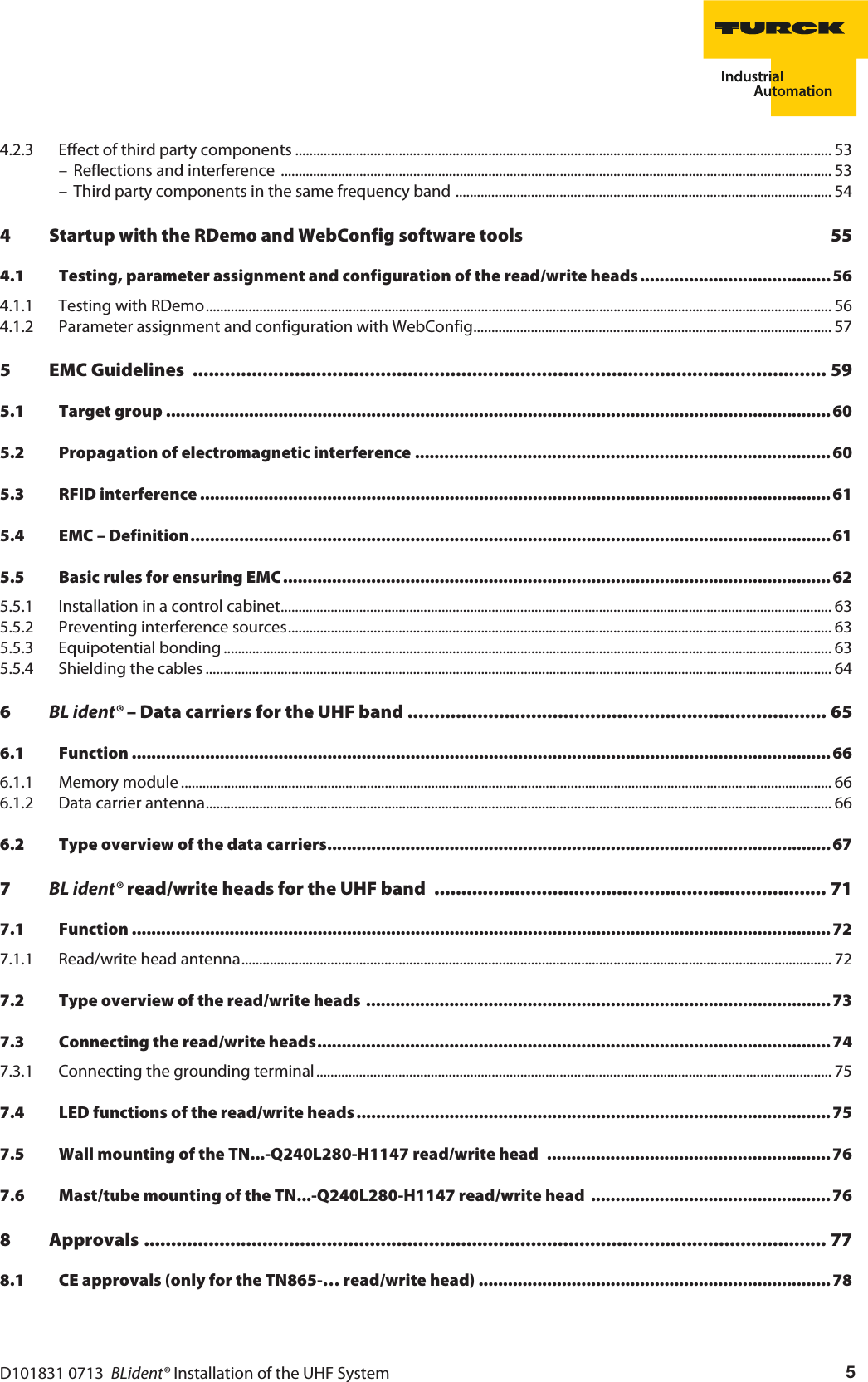
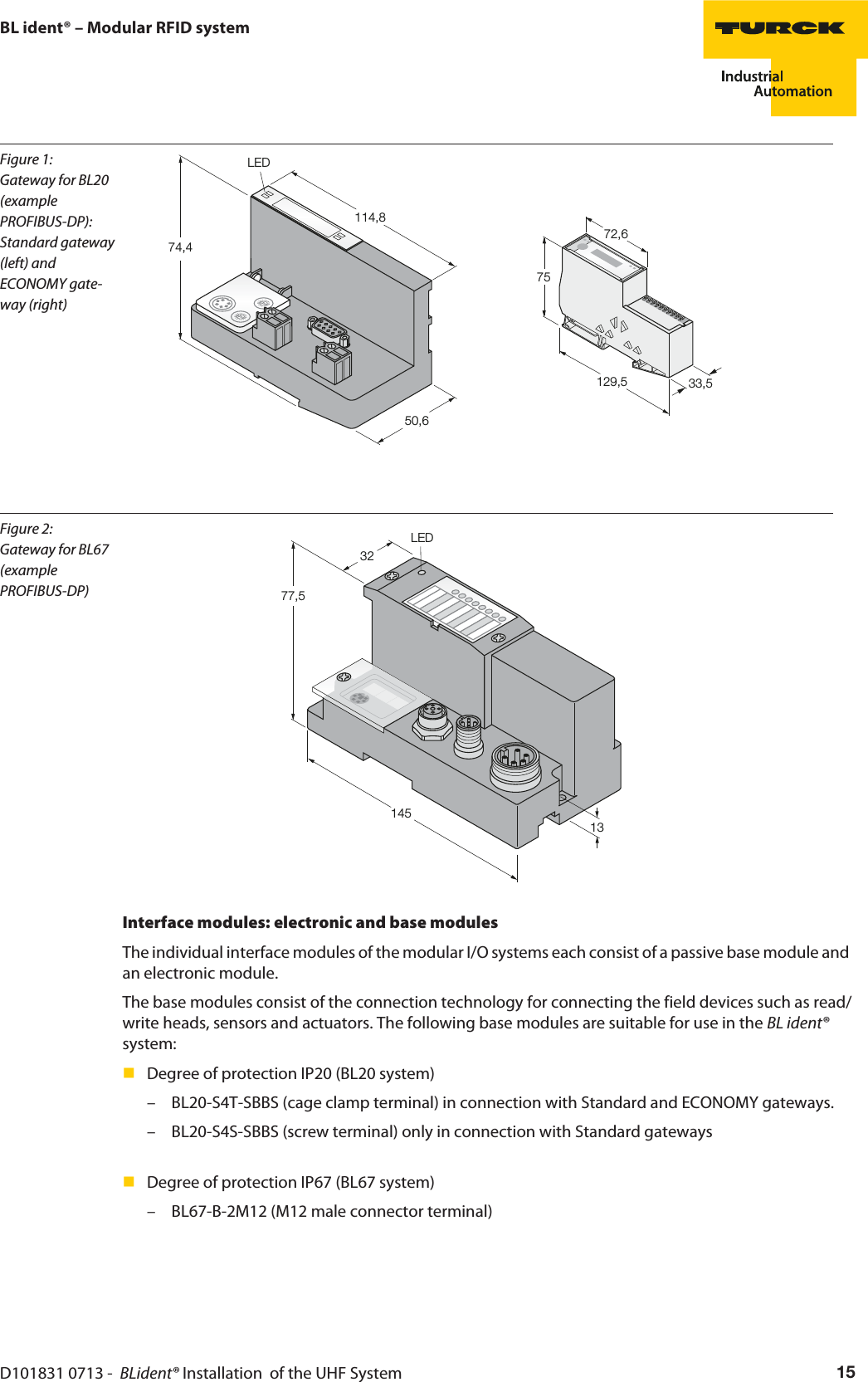
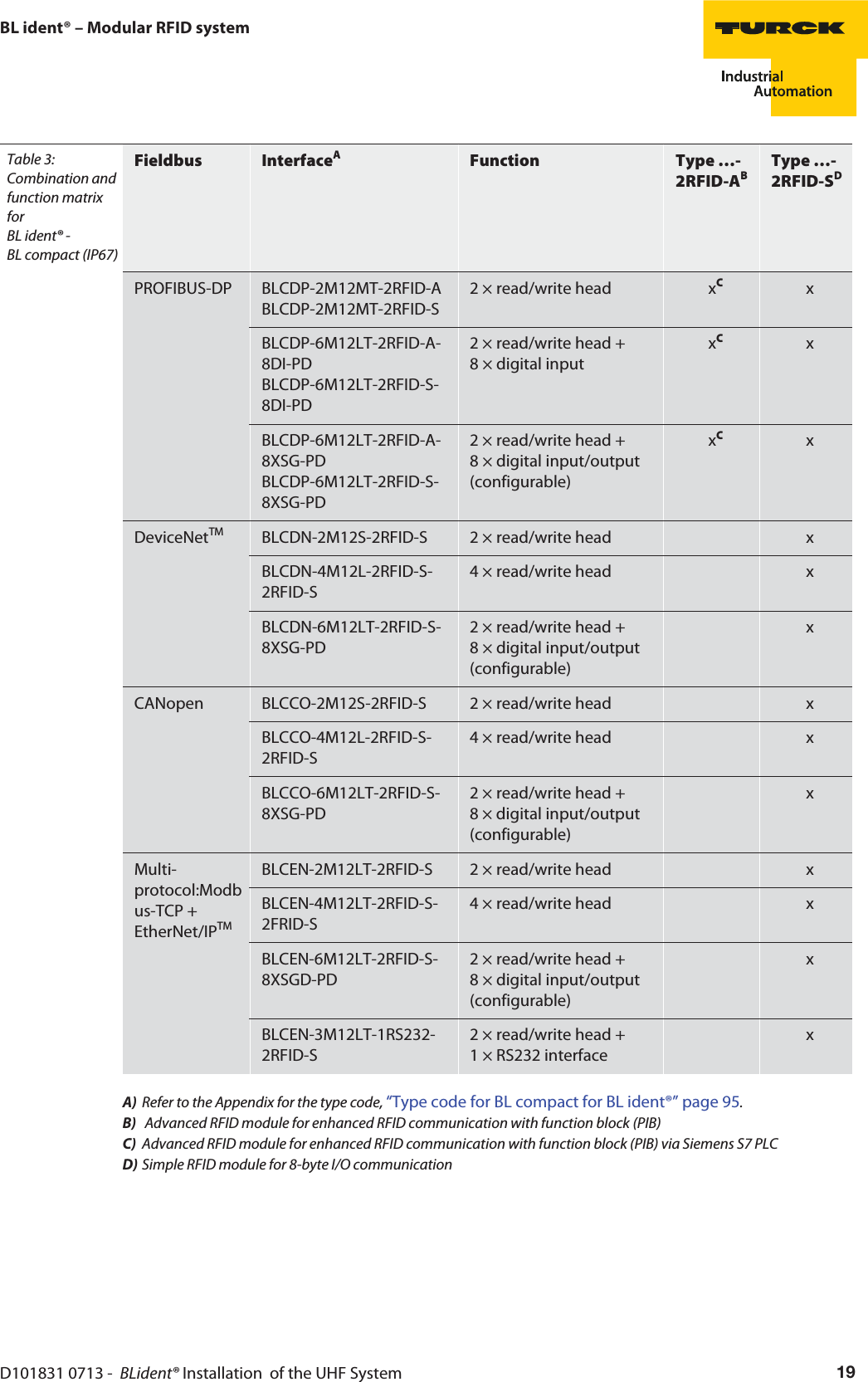
![D101831 0713 - BLident® Installation of the UHF System 29General information on the UHF data carriersOverview of UHF data carriers with Impinj Monza® 4QT chip – private modeThis memory chip has two different states for dividing the memory; Private mode and Public mode. Private mode is the factory setting and is available in operation with the BLxx-2RFID-S, BLxx-2RFID-A electronic modules and BLcompact.The type Impinj Monza® 4QT UHF data carriers in Private mode are provided with a UII memory area of 16 bytes and a freely available user area of 64 bytes.The following table describes the data structure of the data carriers.Table 7: Memory area of Impinj Monza® 4QT - privateBank address[bin.]Bank nameMemory address[hex.]No. of bytesRemark11 User 00hex-1FFhex 64 freely usable10 TID 60hex-BFhex 12 UII public30hex-5Fhex 6 Serial number20hex-2Fhex 2 Extended TID header10hex-1Fhex 2 Manufacturer ID + model number00hex-0Fhex 2 11100010 + manufacturer ID01 UII private 20hex-9Fhex 16 UII10hex-1Fhex 2 Protocol control bits00hex-0Fhex 2 Checksum CRC-1600 Reserved 20hex-3Fhex 4 Password for memory access00hex-1Fhex 4 Password to deactivate the memory](https://usermanual.wiki/Hans-Turck-and-KG/TN902-Q120L130.User-Manual/User-Guide-2419793-Page-29.png)
![The TURCK BL ident® UHF SystemD101831 0713 - BLident® Installation of the UHF System30Overview of UHF data carriers with Impinj Monza® 4QT chip – public modeNoteThe following specifications for the Impinj Monza 4QT in public mode is only for information purposes since public mode is not supported by the BL ident® system.The type Impinj Monza® 4 QT UHF data carriers are provided in public mode with a UII memory area of 12 bytes.The following table describes the data structure of the data carriers.Table 8: Memory area of Impinj Monza® 4QT - publicBank address[bin.]Bank nameMemory address[hex.]No. of bytesRemark10 TID 10hex-1Fhex 2 Manufacturer ID + model number00hex-0Fhex 2 11100010 + manufacturer ID01 UII public 20hex-7Fhex 12 UII10hex-1Fhex 2 Protocol control bits00hex-0Fhex 2 Checksum CRC-1600 Reserved 20hex-3Fhex 4 Password for memory access00hex-1Fhex 4 Password to deactivate the memoryOverview of UHF data carriers with Impinj Monza® 5 chipThe type Impinj Monza® 5 UHF data carriers are provided with a UII memory area of 16 bytes.The following table describes the data structure of the data carriers.Table 9: Memory area of Impinj Monza® 5Bank address[bin.]Bank nameMemory address[hex.]No. of bytesRemark10 TID 30hex-5Fhex 6 Serial number20hex-2Fhex 2 Extended TID header10hex-1Fhex 2 Model number00hex-0Fhex 2 11100010 + manufacturer ID01 UII 20hex-9Fhex 16 UII10hex-1Fhex 2 Protocol control bits00hex-0Fhex 2 Checksum CRC-1600 Reserved 20hex-3Fhex 4 Password for memory access00hex-1Fhex 4 Password to deactivate the memory](https://usermanual.wiki/Hans-Turck-and-KG/TN902-Q120L130.User-Manual/User-Guide-2419793-Page-30.png)
![D101831 0713 - BLident® Installation of the UHF System 31General information on the UHF data carriersOverview of UHF data carriers with Alien Higgs® 3 chipThe type Alien Higgs® 3 UHF data carriers are provided with a UII memory area of 12 bytes and a freely available user area of 64 bytes.The following table describes the data structure of the data carriers.Table 10: Memory area of Alien Higgs® 3Bank address[bin.]Bank nameMemory address[hex.]No. of bytesRemark11 User 00hex-1FFhex 64 freely usable10 TID 60hex-BFhex 12 reserved20hex-5Fhex 8 Serial number10hex-1Fhex 2 Model number00hex-0Fhex 2 Manufacturer ID01 UII 20hex-7Fhex 12 UII10hex-1Fhex 2 Protocol control bits00hex-0Fhex 2 Checksum CRC-1600 Reserved 20hex-3Fhex 4 Password for memory access00hex-1Fhex 4 Password to deactivate the memory](https://usermanual.wiki/Hans-Turck-and-KG/TN902-Q120L130.User-Manual/User-Guide-2419793-Page-31.png)
![The TURCK BL ident® UHF SystemD101831 0713 - BLident® Installation of the UHF System32Overview of UHF data carriers with NXP U-Code G2XM/G2XL chipThe type NXP U-Code G2XM/G2XL UHF data carriers are provided with a UII memory area of 30 bytes.The following table describes the data structure of the data carriers.Table 11: Memory area of NXP U-Code G2XM/G2XLBank address[bin.]Bank nameMemory address[hex.]No. of bytesRemark11 User 00hex-1FFhex 64 only with NXP U-Code G2XM,NXP U-Code G2XL has 0 bytes10 TID 20hex-3Fhex 4 Serial number10hex-1Fhex 2 Model number00hex-0Fhex 2 Manufacturer ID, fixed 1110001001 UII 20hex-10Fhex 30 UII10hex-1Fhex 2 Protocol control bits00hex-0Fhex 2 Checksum CRC-1600 Reserved 20hex-3Fhex 4 Password for memory access00hex-1Fhex 4 Password to deactivate the memory](https://usermanual.wiki/Hans-Turck-and-KG/TN902-Q120L130.User-Manual/User-Guide-2419793-Page-32.png)
![D101831 0713 - BLident® Installation of the UHF System 33General information on the UHF data carriersOverview of UHF data carriers NXP U-Code G2IM chipThe type NXP U-Code G2IM data carriers are provided with a UII memory area of 16 bytes and a freely available user area of 64 bytes and a user TID of 14 bytes.The following table describes the data structure of the data carriers.Table 12: Memory area of NXP U-Code G2IMBank address[bin.]Bank nameMemory address[hex.]No. of bytesRemark11 User 00hex-27Fhex 64 freely usable10 TID 60hex-CFhex 14 User TID, freely usable30hex-5Fhex 6 Serial number20hex-2Fhex 2 Extended TID header14hex-1Fhex 2 Model number08hex-13hex 2 fixed 00000000011000hex-07hex 1 Manufacturer ID, fixed 1110001001 UII 20hex-9Fhex 16 UII10hex-1Fhex 2 Protocol control bits00hex-0Fhex 2 Checksum CRC-1600 Reserved 20hex-3Fhex 4 Password for memory access00hex-1Fhex 4 Password to deactivate the memory](https://usermanual.wiki/Hans-Turck-and-KG/TN902-Q120L130.User-Manual/User-Guide-2419793-Page-33.png)
![The TURCK BL ident® UHF SystemD101831 0713 - BLident® Installation of the UHF System34Overview of UHF data carriers with NXP U-Code G2IL chipThe type NXP U-Code G2IL UHF data carriers are provided with a UII memory area of 16 bytes.The following table describes the data structure of the data carriers.Table 13: Memory area of NXP U-Code G2ILBank address[bin.]Bank nameMemory address[hex.]No. of bytesRemark10 TID 20hex-3Fhex 6 Serial number20hex-2Fhex 2 Extended TID header14hex-1Fhex 2 Model number00hex-13hex 2 11100010 + manufacturer ID01 UII 200hex-20Fhex 2 Configuration word20hex-9Fhex 16 UII10hex-1Fhex 2 Protocol control bits00hex-0Fhex 2 Checksum CRC-1600 Reserved 20hex-3Fhex 4 Password for memory access00hex-1Fhex 4 Password to deactivate the memory](https://usermanual.wiki/Hans-Turck-and-KG/TN902-Q120L130.User-Manual/User-Guide-2419793-Page-34.png)
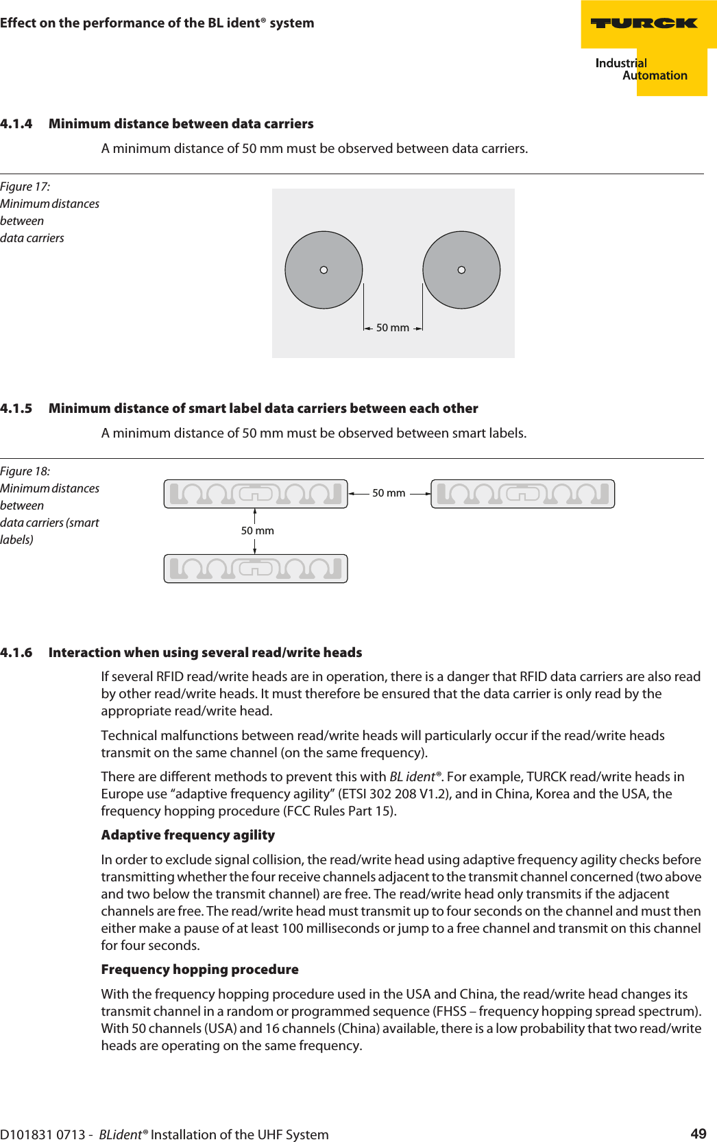
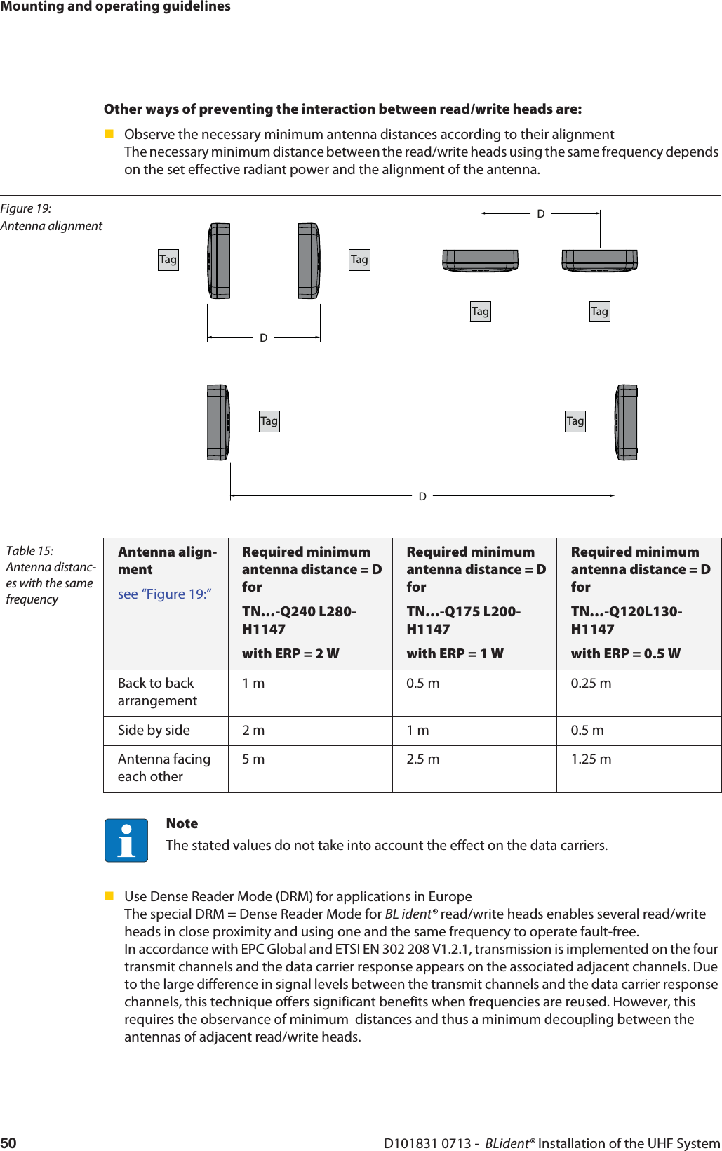
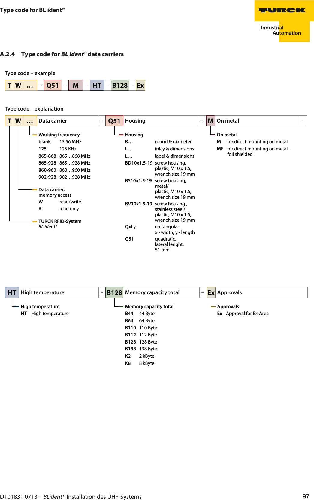
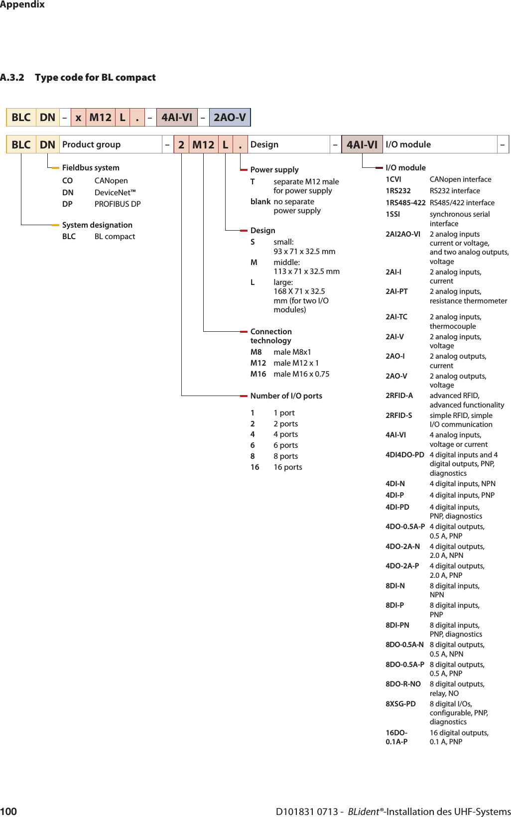
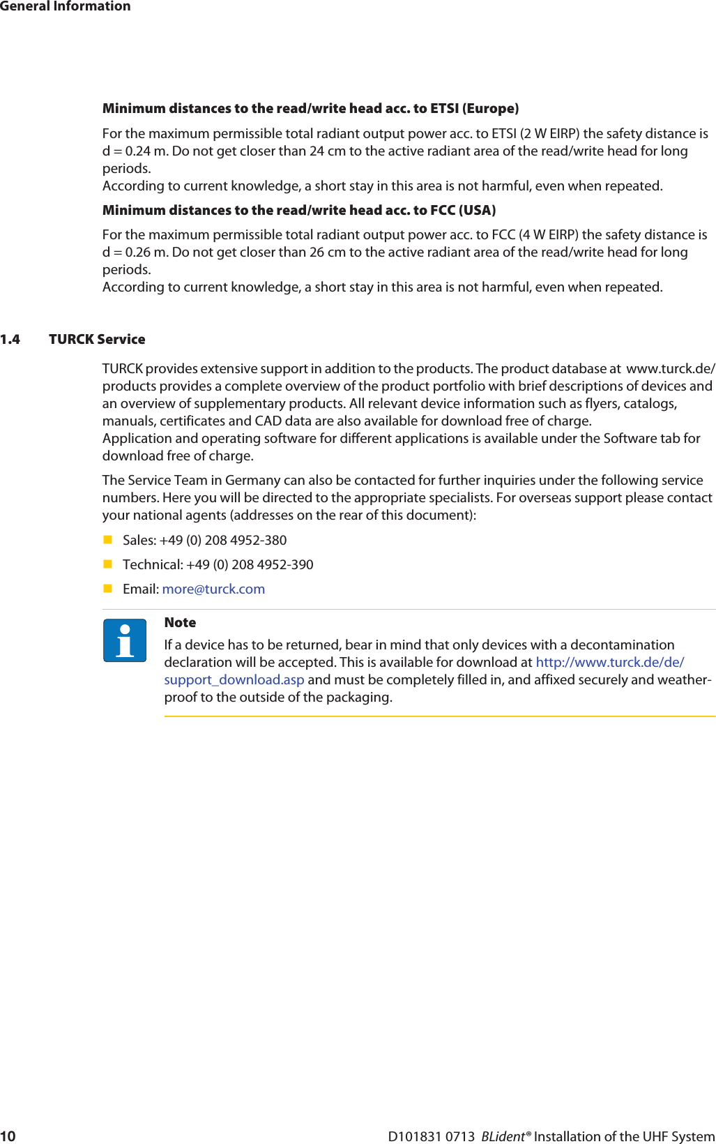
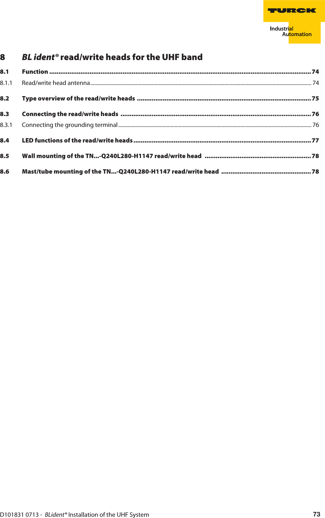
![NoteWhen the read/write heads are used in Europe, the use of DRM filters is advantageous if several read/write heads are operated in a narrow space. These DRM filters can be switched on manually in the WebConfig software in the Link profiles menu.D101831 0713 - BLident® Installation of the UHF System 51Effect on the performance of the BL ident® systemSynchronize read/write heads using a higher-level controller In order to minimize the interference between read/write heads, their mode should be as synchronized as possible, e.g. via a central controller (PLC), or the TDMA procedure should be used for the transmission. If possible there should always only be one read/write head active for read or write modes and its activation time should be at a minimum.Trigger read/write heads In order to minimize the operating time of the radio field to the time required for communication with the data carrier, the read/write heads should if possible only be triggered on, for example, by means of an additional switch sensor that only activates the radio field if the data carriers are in the sensing range of the read/write head.Create a channel assignment plan TURCK recommends the creation of a channel assignment plan for RFID applications in Europe. For this the read/write heads using the same channel in a spatial environment (e.g. machine hall) should be located as far apart from each other as possible (see “Table 15:”).The following frequency ranges with the associated channels are used in Europe, Korea, the USA or China:Figure 20: Frequency ranges in Europedata carrier response865.0 865.7 866.3 866.9 867.5 868.0600 kHz 200 kHzread/write signalmax. 2.0 W (ERP) f [MHz]NoteFor applications in Europe, the read/write heads should be assigned to and use equally the four channels provided, i.e. when using, for example, 5 read/write heads, not all of them should run on channel 4 whilst channels 7, 10 and 13 remain free.](https://usermanual.wiki/Hans-Turck-and-KG/TN902-Q120L130.User-Manual/User-Guide-2419793-Page-51.png)
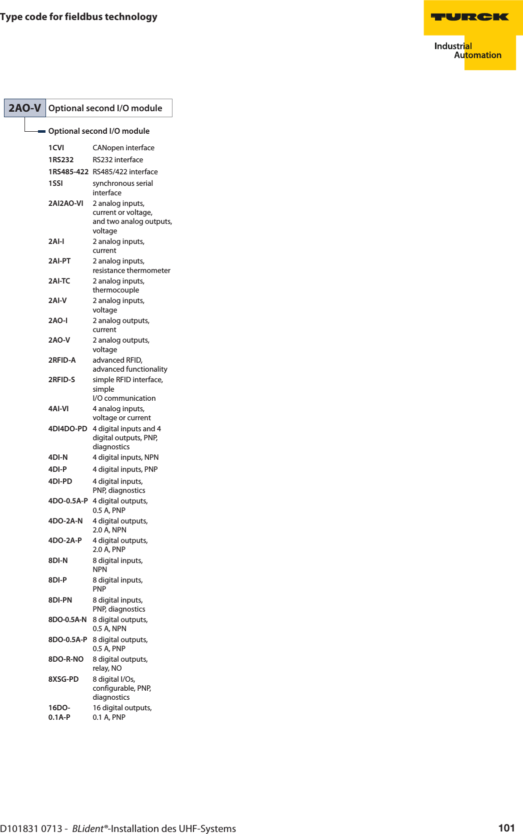
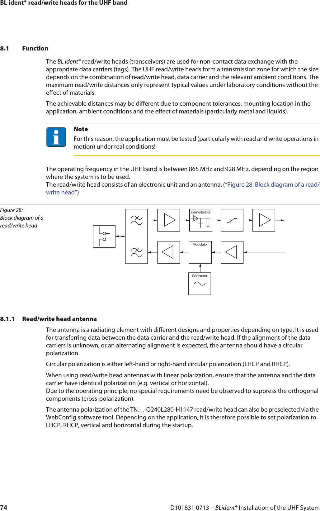
![Figure 21: Frequency ranges in Korea, Frequency hopping proceduredata carrier response917.0 917.3 917.9 918.5 919.1919.7 920,3 920,8600 kHz 200 kHzread/write signalmax. 4.0 W (EIRP)f [MHz]Figure 22: Frequency ranges in the USA, frequen-cy hopping proce-dure902.5902.0902.75927.5 928.0927.25500 kHzmax. 4.0 W (EIRP)f [MHz]50 channelsFigure 23: Frequency ranges in China, Frequency hopping procedure920.5920.125920.625924.5 924.875924.375250 kHzmax. 2.0 W (ERP)f [MHz]16 channelsMounting and operating guidelinesD101831 0713 - BLident® Installation of the UHF System52](https://usermanual.wiki/Hans-Turck-and-KG/TN902-Q120L130.User-Manual/User-Guide-2419793-Page-52.png)
![D101830 0713 - BLident® Installation of the UHF System 69Type overview of the data carriers7.2 Type overview of the data carriersThe RFID operating frequencies in the UHF band are subject to national specifications, for example 865...868 MHz in Europe and 902...928 MHz in the USA. TURCK offers different data carrier variants that are specially designed and optimized for national frequency bands in order to achieve as large a transmission range as possible. Wide-band multi-range data carriers for international use are also available as an alternative. Besides the frequency ranges, the selection criteria for the data carrier depend on the application at hand. Data carriers for the direct mounting on metal, for attaching with a metal loop, as well as smart labels and high temperature versions are therefore available in addition to the standard mounting forms. Customized data carrier solutions that are tailored to the relevant application are also available on request.Table 16: Type overview of the data carriersDimensions/housing lengthMemory size[Byte]Memory Operating tempera-ture[° C]Special featuresType designation28,5367ø 2,522112 EEPROM -40...+85 Designed exclusively for direct mounting on metal,high temperatureTW865-868-Q22L36-M-HT-B112275,527ø 3,4ø 7,4112 EEPROM -20...+80 Designed exclusively for direct mounting on metal,TW865-868-Q27-M-B112TW902-928-Q27-M-B112141260110 EEPROM -35...+85 Suitable for direct mounting on metalTW865-868-Q14L60-M-B110TW902-928-Q14L60-M-B110](https://usermanual.wiki/Hans-Turck-and-KG/TN902-Q120L130.User-Manual/User-Guide-2419793-Page-69.png)
![45,957,519 20108,5BL ident® – Data carriers for the UHF bandD101830 0713 - BLident® Installation of the UHF System70110 EEPROM -30...+70 Clip with metal loopfor fixingCustomizedlabelingTW865-928-Q20L58-B1102577370ø 3112 EEPROM -40...+70 Flexible mounting form, for fixingon bent or irregularsurfacesTW860-960-Q25L77-B-B11282971527ø 5,3112 EEPROM -40...+80 suitable for direct mounting on metal,suitable for outdoor applicationsTW860-960-Q27L97-M-B1124051,547,510ø 5 (2x)110 EEPROM -40...+85 Designed exclusively for directmounting on metalTW865-868-Q47L51-M-B110TW902-928-Q47L51-M-B110Table 16: (cont.) Type overview of the data carriersDimensions/housing lengthMemory size[Byte]Memory Operating tempera-ture[° C]Special featuresType designation](https://usermanual.wiki/Hans-Turck-and-KG/TN902-Q120L130.User-Manual/User-Guide-2419793-Page-70.png)
![3,2ø 50ø 4,9D101830 0713 - BLident® Installation of the UHF System 71Type overview of the data carriers110 EEPROM -20...+85 Ø 50 mm withcentral holeTW865-868-R50-B110TW902-928-R50-B11051516,5ø 5,5ø 10,5110 EEPROM -25…+85 High temperatureTW865-868-Q51-HT-B1107310 14706110 EEPROM -35...+60 can be inserted in drill holeswith Ø 13 mm, e.g. woodTW860-960-L73-14-C-B1101876,221110 EEPROM -35...+85 self-adhesive, suitable fordirect mounting on metalTW865-928-L76-18-21-F-M-B11020801,144 EEPROM -20...+65 Smart label TW865-868-L80-20-T-B44Table 16: (cont.) Type overview of the data carriersDimensions/housing lengthMemory size[Byte]Memory Operating tempera-ture[° C]Special featuresType designation](https://usermanual.wiki/Hans-Turck-and-KG/TN902-Q120L130.User-Manual/User-Guide-2419793-Page-71.png)
![11939715BL ident® – Data carriers for the UHF bandD101830 0713 - BLident® Installation of the UHF System7244 EEPROM -10…+85 Smart label TW860-960-L97-15-F-B44Table 16: (cont.) Type overview of the data carriersDimensions/housing lengthMemory size[Byte]Memory Operating tempera-ture[° C]Special featuresType designation](https://usermanual.wiki/Hans-Turck-and-KG/TN902-Q120L130.User-Manual/User-Guide-2419793-Page-72.png)

![GlossaryD101831 0713 - BLident® Installation of the UHF System84EMCElectromagnetic compatibility (EMC) denotes the normally desired state in which technical devices do not cause or suffer undesired electrical or electromagnetic interference to or from other devices in the same environment.EPCThe electronic product code (EPC) is an international code system for a unique identification number, by which products, stock-keeping units (outer packaging, transport pallets etc.), systems, services, documents, reusable transport containers and locations (e.g. buildings (sections) or warehouse sites) can be uniquely designated and identified. In combination with RFID technology it can be used for the detection and tracing of objects fitted with a transponder with EPC without visual or physical contact.EPC enables the unique identification of objects by class or type (e.g. a GTIN) and instance (in this case, a serialized GTIN[1]) (e.g. commercial unit, stock-keeping unit or transport container). For this the EPC is stored on a data carrier which is fitted to the object to be identified. An RFID chip in compliance with ISO 18000-6C is normally used as a data carrier to store and transmit the code. GroundIn electrical engineering, the name given to a conductive area with an electrical potential of zero at any point. The electrical potential of the ground may not equal zero in the area around grounding devices, in which case this is called the “reference ground”.GroundingThe connection of an electrically conductive component to the ground using a grounding device.Grounding deviceOne or several components that have direct and good contact with the ground.ERP/EIRPThe effective radiated power (ERP) is the product of the power supplied in the transmitting antenna multiplied by the antenna gain (referenced to a half-wave dipole). If no direction is stated, the value applies to the main direction of radiation from the transmitting antenna where its greatest antenna gain is present at the same time. If the antenna gain is referenced to the isotropic antenna, it is called EIRP (Effective Isotropic Radiated Power).FFieldbusData network on the sensor/actuator level. A fieldbus connects the devices on the fieldbus level with a control device. A fieldbus offers high transmission security and a real-time behavior.Frequence hoppingThis procedure is designed to prevent mutual interference between read/write heads. For this the read/write head changes its transmitting channel according to a random or programmed sequence (FHSS). With 16 channels that are permitted for simultaneous operation in China and 50 channels in the USA, this reduces the probability that two read/write heads are operating on the same frequency.GGSD - General Station Description(previously device master file) The GSD file describes the characteristics of the devices used in PROFIBUS-DP. The GSD file is a readable text file and is supplied in different languages. Configuration tools require the device information in order to complete the configuration and commissioning. The GSD file normally contains general information (e.g. vendor name and version) and with modular devices the communication features (e.g. module designations, texts for diagnostic messages, parameter options, parameter names) of the individual modules. HHexadecimalNumerical system with a base of 16. The sequence begins with 0 to 9 and continues with the letters A, B, C, D, E and F.](https://usermanual.wiki/Hans-Turck-and-KG/TN902-Q120L130.User-Manual/User-Guide-2419793-Page-84.png)