Hangzhou Gubei Electronics Technology BL3329-P BL3329-P User Manual 1
Hangzhou Gubei Electronics Technology Co.,Ltd BL3329-P 1
UserManual.wiki
>
Hangzhou Gubei Electronics Technology
>
BL3329 P User Manual
User manual_1
Navigation menu
Upload a User Manual
Namespaces
Wiki Guide
HTML
PDF
Info
Views
User Manual
Discussion / Help
Navigation
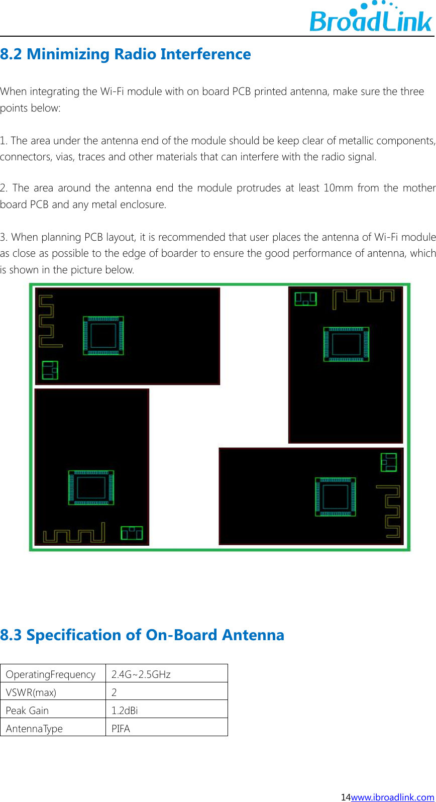
![17www.ibroadlink.comAppendix B Reference paper(Quentin respible)[1] IEEE 802.11b/g/n- published IEEE 802.11-2007wireless networking standard andpublished IEEE 802.11-2012 standard for Information technology - Clause 19 of thepublishedIEEE 802.11-2007 standard, and Clause 19 of the published IEEE802.11-2012 standard.Contact UsHangzhou Gubei Electronics Technology Co., Ltd.Room 106, Building 1, No. 611 Jianghong Road, Binjiang, Hangzhou, Zhejiang, P.R.ChinaT: +86-571-85159281 F: +86-571-86631817E: intl@broadlink.com.cn W: www.ibroadlink.com.cnThis device complies with Part 15 of the FCC Rules / Industry Canada licence-exemptRSS standard(s). Operation is subject to the following two conditions: (1) this devicemay not cause harmful interference, and (2) this device must accept any interferencereceived, including interference that may cause undesired operation.Le présent appareil est conforme aux CNR d'Industrie Canada applicables auxappareils radio exempts de licence. L'exploitation est autorisée aux deux conditionssuivantes : (1) l'appareil ne doit pas produire de brouillage, et (2) l'utilisateur del'appareil doit accepter tout brouillage radioélectrique subi, même si le brouillage estsusceptible d'en compromettre le fonctionnement.](https://usermanual.wiki/Hangzhou-Gubei-Electronics-Technology/BL3329-P/User-Guide-3629098-Page-18.png)