Hallmark DKL1608 2.4G module User Manual DKL1608 S
Hallmark Cards, Inc. 2.4G module DKL1608 S
UserManual.wiki
>
Hallmark
>
DKL1608 User Manual
>
User Manual.pdf
Contents
1.
User Manual Statement.pdf
2.
User Manual.pdf
User Manual.pdf
Navigation menu
Upload a User Manual
Namespaces
Wiki Guide
HTML
PDF
Info
Views
User Manual
Discussion / Help
Navigation
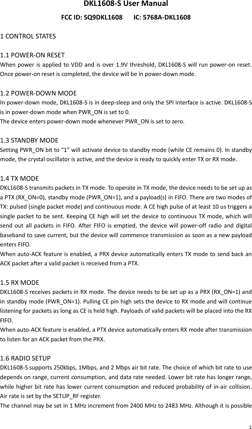
![2to set the channel frequency higher than 2483 MHz, it is not recommended for this may violate regional regulations. For 250kbps and 1Mbps operation, the channel may be set in 1 MHz increment; for 2Mbps operation, the channel spacing should be 2 MHz or more. Channel selection is set by the RF_CH register. In addition to the device address, the bit rate and channel frequency need to be set the same for the radios to communicate with each other. 1.7 RSSI RECORDER DKL1608-S features an advanced RSSI block and control, allowing the receiver host to collect detailed information of the current RX channel. There are two decision thresholds that can be individually set. An RSSI recorder generates a log of the channel traffic. With two decision thresholds, the host can separate the receiving signal into three ranges: low, medium, and high. The RSSI recorder consists of two 8-bit shift registers corresponding to the two thresholds, and it keeps track of the RSSI readings for the past 8 time slots. A single time slot is 128 us. The most recent RSSI record is placed at the MSB of the shift register, and the bits are shifted toward LSB as time progresses. This recording RSSI scheme can be useful in detecting complex channel behaviors such as fading, interference, and may assist MCU in channel selection. The RSSI enable setting and RSSI readout are in the RSSI register setting. The RSSI threshold and recorder are in address 0x18. Figure 6 shows the basic concept of the RSSI recorder scheme. At read point 1, [RSSI1, RSSI2] readout will be [0, 0], RSSIREC1 readout will be 0x1F and RSSIREC2 readout will be 0x06; at read point 2, [RSSI1, RSSI2] will read [0, 1], RSSIREC1 will read 0xF0 and RSSIREC2 will read 0x10. DKL1608-S also has a unique identifier encoded in [RSSIREC2, RSSIREC1] and can be read right after POR. The 16-bit unique ID for DKL1608-S is 0x7241. To save current, the RSSI is set to be off by default. To turn on the RSSI, enable bit 4 of the RSSI register. The two decision thresholds are also indicated at bit 0 and bit 1 of the RSSI register. RSSI recorder scheme](https://usermanual.wiki/Hallmark/DKL1608.User-Manual-pdf/User-Guide-3301004-Page-2.png)
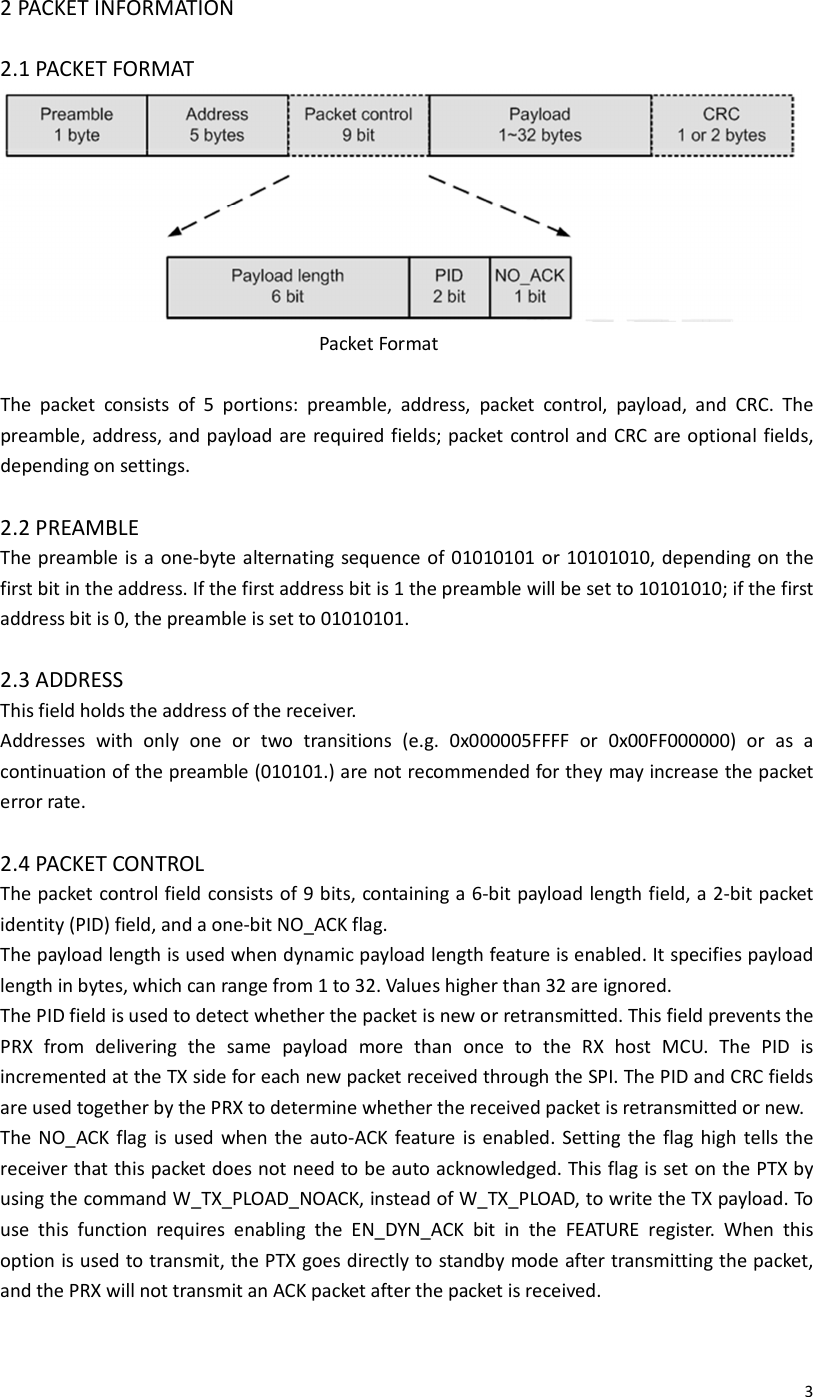
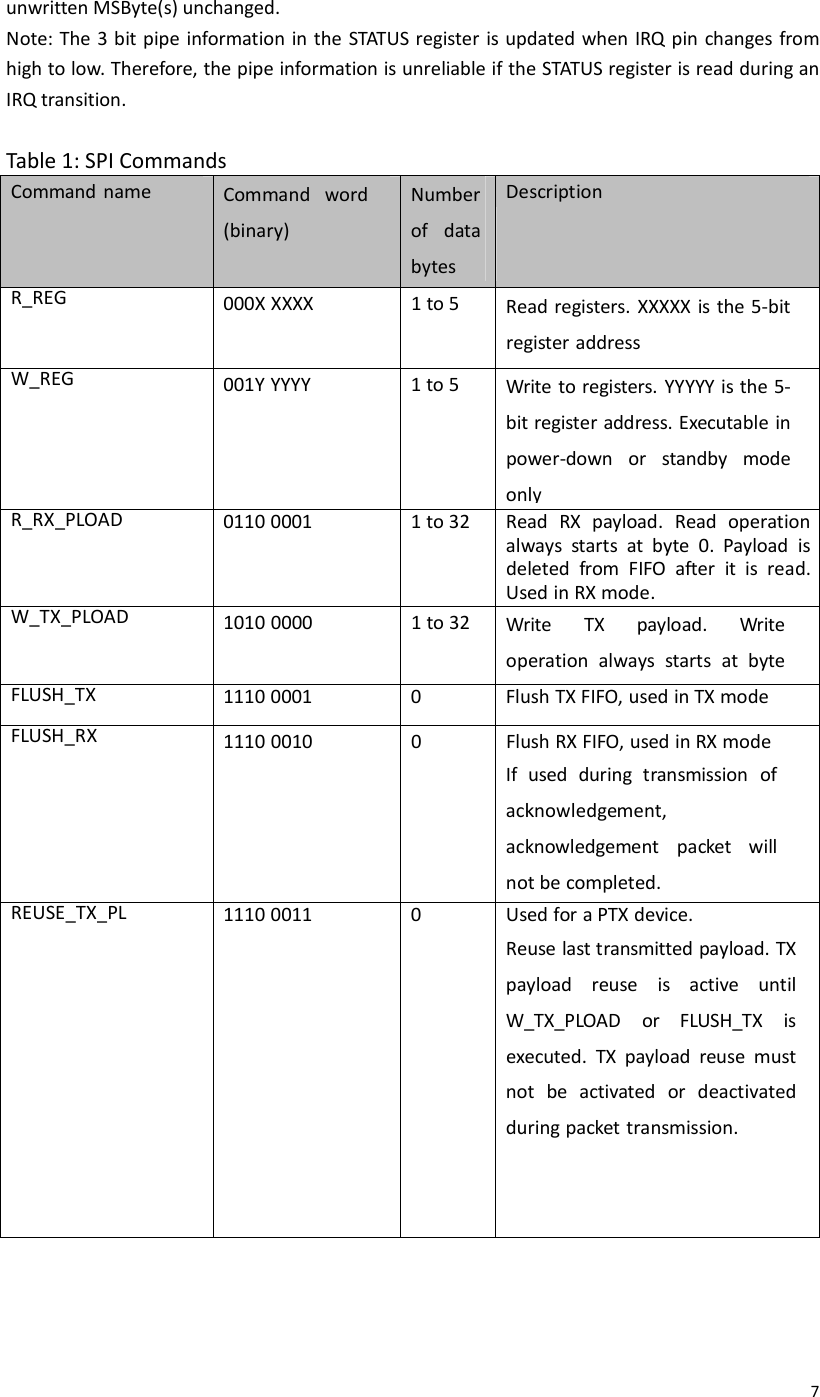
![42.5 PAYLOAD The payload can be 1 to 32 bytes wide. The payload can be set either static or dynamic in length, defined by the packet control field. The default setup is static payload length. The static payload length is set by the RX_PW_Px register on the receiver side. Payload length on the transmitter side is set by the number of bytes placed in the TX_FIFO and must be equal to the value set in the RX_PW_Px register on the receiver side. Dynamic payload length enables the transmitter to send packets of variable length to the receiver. The receiver can decode the payload length automatically from the control field value. The MCU can read the received payload length by using R_RX_PL_WID command. To enable dynamic payload, set the EN_DPL bit in the FEATURE register to 1. In RX mode, the DYNPD register must be set. A PTX that transmits to a PRX with dynamic payload enabled must have the DPL_P0 bit in DYNPD set. 2.6 CYCLIC REDUNDANCY CHECK (CRC) The CRC is an error detection mechanism in the packet. It can be set to 1 or 2 bytes and is calculated over the address, packet control field, and payload. The polynomial for 1-byte CRC is X8+ X2+ X + 1, with an initial value of 0xFF. The polynomial for 2-byte CRC is X8+ X2+ X + 1, with an initial value of 0xFFFF. The CRCC bit in the CFG_TOP register sets the CRC length, and EN_CRC controls whether CRC is used. The CRC is a mandatory field for packets with auto-ACK or dynamic payload length enabled, and will override the EN_CRC bit setting. If CRC is enabled, packets will be dropped if CRC fails. 2.7 PACKET HANDLING In TX mode, the PHY engine fetches a payload from TX FIFO, assembles the payload into a packet and transmits the packet in a short burst. After transmission, if the PTX packet has the NO_ACK flag set, the device sets TX_DS to 1 and gives an active low interrupt IRQ to MCU. If the PTX packet is an auto-ACK one, the PTX needs to receive an ACK from the PRX and then asserts the TX_DS IRQ. The receiver continuously listens to the air channel for radio signal, and once it is synchronized to a likely signal, the PHY engine will validate the address and CRC of the possible packet. If a valid packet is detected and is a new one, the PHY engine writes the payload to RX FIFO, sets RX_DR to 1 and gives an active low interrupt IRQ to MCU. When auto-acknowledge is enabled (EN_AA=1), the PTX will enter RX mode after transmission to wait for an ACK packet. If an ACK is not received within delay set by ARD[3:0], the PTX re-transmits the original packet and enters RX mode to wait for ACK. The above action is repeated until an ACK packet is received or the number of re- transmission exceeds a threshold set by ARC[3:0]. If the latter threshold is met, the PTX will set MAX_RT to 1 and give an active low interrupt IRQ to MCU. Two packet loss counters (ARC_CNT and PLOS_CNT) are incremented each time a packet is lost. The ARC_CNT counts the number of retransmissions for the current transaction. The PLOS_CNT counts the total number of retransmissions since the last channel change. Initiating a new transmission resets the ARC_CNT. Writing to the RF_CH register resets the PLOS_CNT. The ARC_CNT and the PLOS_CNT are in the OBSERVE_TX register. They may be](https://usermanual.wiki/Hallmark/DKL1608.User-Manual-pdf/User-Guide-3301004-Page-4.png)
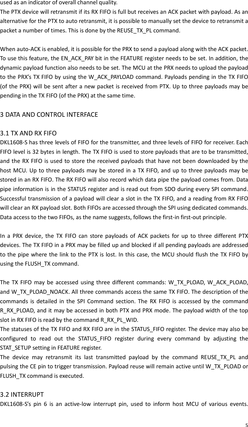
![11 ENRX_P5 5 0 R/W Enable data pipe 5 ENRX_P4 4 0 R/W Enable data pipe 4 ENRX_P3 3 0 R/W Enable data pipe 3 ENRX_P2 2 0 R/W Enable data pipe 2 ENRX_P1 1 1 R/W Enable data pipe 1 ENRX_P0 0 1 R/W Enable data pipe 0 03 SETUP_AW Address width & timing setup Reserved 7:4 0 R/W Unused Reserved 3:2 11 R/W Reserved setting, must be set to 11 Reserved 1:0 11 R/W Reserved setting, must be set to 11 04 SETUP_RETR Automatic retransmission setup ARD[3:0] 7:4 0000 R/W Automatic retransmission delay 0000: wait 250uS 0001: wait 500uS . ARC[3:0] 3:0 0011 R/W Auto retransmit count 0000: disabled 0001: up to 1 re-transmit on fail of AA 05 RF_CH RF channel Reserved 7 0 R/W Unused RF_CH[6:0] 6:0 0x02 R/W Set frequency channel in 1 MHz increment, 0x00 is 2400 MHz 06 SETUP_RF RF settings EN_CW 7 0 R/W Enable continuous carrier when set high Confirm during chip verification EN_PRBS 6 0 R/W Enable PRBS bit stream when set high; EN_CW also needs to be enabled RF_DR_LOW 5 0 R/W See RF_DR_HIGH](https://usermanual.wiki/Hallmark/DKL1608.User-Manual-pdf/User-Guide-3301004-Page-11.png)
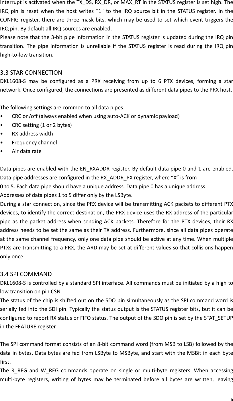
![12 TX_ATTN 4 0 R/W TX low-power mode Confirm actual attenuation level RF_DR_HIGH 3 0 R/W [RF_DR_LOW, RF_DR_HIGH] 00: 1Mbps 01: 2Mbps 10: 250kbps RF_PWR[1:0] 2:1 01 R/W Set RF output power in TX mode 00: -18 dBm 01: -12 dBm 10: -6 dBm Reserved 0 0 R/W Unused 07 STATUS Status (read-out from SDO pin during SPI command word input); SDO output may be adjusted Reserved 7 0 R/W Unused RX_DR 6 0 R/W Data ready RX FIFO interrupt. Asserted when new data arrives at RX FIFO. Write 1 to clear bit TX_DS 5 0 R/W Data sent TX FIFO interrupt. Asserted when packet transmitted. If auto-ACK is activated, this bit is set high only when ACK is received. Write 1 to clear MAX_RT 4 0 R/W Maximum number of TX retransmit interrupt. Write 1 to clear bit. If MAX_RT is asserted it must be cleared to enable further operation RX_P_NO[2:0] 3:1 111 R Data pipe number for the payload available for reading from RX_FIFO 000~101: data pipe number (0~5) TX_FULL 0 0 R 0: TX FIFO available 1: TX FIFO full 08 OBSERVE_TX Transmission observation PLOS_CNT[3:0] 7:4 0000 R Count lost packets. Overflow protected to 15, and stops at maximum value until reset. Counter reset by writing to RF_CH ARC_CNT[3:0] 3:0 0000 R Count retransmitted packets. Counter resets when transmission of a new packet starts 09 RSSI TSSI and RSSI indicator/control Reserved 7 0 R/W Must be 0 for normal operation Reserved 6 0 R/W Must be 0 for normal operation Reserved 5 0 R/W Must be 0 for normal operation](https://usermanual.wiki/Hallmark/DKL1608.User-Manual-pdf/User-Guide-3301004-Page-12.png)
![13 EN_RSSI 4 0 R/W Enable RSSI Reserved 3 0 R Reserved register readout Reserved 2 0 R Reserved register readout RSSI2 1 0 R RSSI indicator at threshold 2 RSSI1 0 0 R RSSI indicator at threshold 1 0A RX_ADDR_P0 39:0 0xE7 E7E7 E7E7 R/W RX address data pipe 0. 5 bytes maximum. LSB byte written first. Number of bytes used set by SETUP_AW. 0B RX_ADDR_P1 39:0 0xC2 C2C2 C2C2 R/W RX address data pipe 1. 5 bytes maximum. LSB byte written first. Number of bytes used set by SETUP_AW. 0C RX_ADDR_P2 7:0 0xc3 R/W RX address data pipe 2. Only LSB are set, MSB bytes use RX_ADDR_P1[39:8] 0D RX_ADDR_P3 7:0 0xc4 R/W RX address data pipe 3. Only LSB are set, MSB bytes use RX_ADDR_P1[39:8] 0E RX_ADDR_P4 7:0 0xc5 R/W RX address data pipe 4. Only LSB are set, MSB bytes use RX_ADDR_P1[39:8] 0F RX_ADDR_P5 7:0 0xc6 R/W RX address data pipe 5. Only LSB are set, MSB bytes use RX_ADDR_P1[39:8] 10 TX_ADDR 39:0 0xE7 E7E7 E7E7 R/W TX address. Used for PTX only. Set RX_ADDR_P0 equal to this address to handle auto acknowledgement 11 RX_PW_P0 Reserved 7:6 00 R/W Unused RX_PW_P0 5:0 0 R/W Number of bytes in RX payload in data pipe 0 (1 to 32). 0: pipe not used 12 RX_PW_P1 Reserved 7:6 00 R/W Unused RX_PW_P1 5:0 0 R/W Number of bytes in RX payload in data pipe 1 (1 to 32). 0: pipe not used 13 RX_PW_P2 Reserved 7:6 00 R/W Unused RX_PW_P2 5:0 0 R/W Number of bytes in RX payload in data pipe 2 (1 to 32). 0: pipe not used 14 RX_PW_P3](https://usermanual.wiki/Hallmark/DKL1608.User-Manual-pdf/User-Guide-3301004-Page-13.png)
![14 Reserved 7:6 00 R/W Unused RX_PW_P3 5:0 0 R/W Number of bytes in RX payload in data pipe 3 (1 to 32). 0: pipe not used 15 RX_PW_P4 Reserved 7:6 00 R/W Unused RX_PW_P4 5:0 0 R/W Number of bytes in RX payload in data pipe 4 (1 to 32). 0: pipe not used 16 RX_PW_P5 Reserved 7:6 00 R/W Unused RX_PW_P5 5:0 0 R/W Number of bytes in RX payload in data pipe 5 (1 to 32). 0: pipe not used 17 STATUS_FIFO FIFO status Reserved 7 0 R/W Unused TX_REUSE 6 0 R Used for a PTX device Pulse the rfce high for at least 10µs to Reuse last transmitted payload. TX payload TX_FULL 5 0 R 1: TX FIFO full 0: available slots in TX FIFO TX_EMPTY 4 1 R 1: TX FIFO empty 0: data in TX FIFO Reserved 3:2 0 R Reserved register readout RX_FULL 1 0 R 1: RX FIFO full 0: available slots in RX FIFO RX_EMPTY 0 1 R 1: RX FIFO empty 0: RX FIFO full 18 RSSIREC RSSI recorder feature Reserved 31:2 6 111 W Reserved Reserved 25:2 2 0110 R Reserved RSSI2_VREF_S EL[2:0] 21:1 9 000 W RX RSSI VREF2 setting 000: -59 dBm, +4dB/step 111: out of range RSSI1X_VREF_ SEL[2:0] 18:1 6 000 W RX RSSI VREF1 setting 000:-69 dBm, +4dB/step](https://usermanual.wiki/Hallmark/DKL1608.User-Manual-pdf/User-Guide-3301004-Page-14.png)
![15 RSSIREC2[7:0 ] 15:8 01110 010 R RSSI2 recorder, MSB is most recent recording, any write command on this register will flush RSSI setting; when RX_ON=0, PWR_ON=0 & CE=0, register will RSSIREC1[7:0 ] 7:0 01000 001 R RSSI1 recorder, MSB is most recent recording, any write command on this register will flush RSSI setting; when RX_ON=0, PWR_ON=0 & CE=0, register will 1C DYNPD Dynamic payload length Reserved 7:6 00 R/W Unused DPL_P5 5 0 R/W Set 1 to enable dynamic payload length data pipe 5 (requires EN_DPL & ENAA_P5) DPL_P4 4 0 R/W Set 1 to enable dynamic payload length data pipe 4 (requires EN_DPL & ENAA_P4) DPL_P3 3 0 R/W Set 1 to enable dynamic payload length data pipe 3 (requires EN_DPL & ENAA_P3) DPL_P2 2 0 R/W Set 1 to enable dynamic payload length data pipe 2 (requires EN_DPL & ENAA_P2) DPL_P1 1 0 R/W Set 1 to enable dynamic payload length data pipe 1 (requires EN_DPL & ENAA_P1) DPL_P0 0 0 R/W Set 1 to enable dynamic payload length data pipe 0 (requires EN_DPL & ENAA_P0) 1D FEATURE Features STAT_SETUP[1 :0] 7:6 00 R/W Adjust the output of SDO during command input 00: default, SDO output is STATUS 01: RX readout mode, the SDO output MAX_RT and TX_FULL bit is replaced by RSSI1 and RSSI2 readout Reserved 5:3 000 R/W Unused EN_DPL 2 0 R/W Set 1 enables dynamic payload length EN_ACK_PAY 1 0 R/W Set 1 enables payload on ACK EN_DYN_ACK 0 0 R/W Set 1 enables the W_TX_PAYLOAD_NOACK command 1F RESERVED Reserved register Reserved 7:0 0 R/W 8’h00: default settings](https://usermanual.wiki/Hallmark/DKL1608.User-Manual-pdf/User-Guide-3301004-Page-15.png)