HUAC F27-5S Wireless Cellular Repeater User Manual
SHENZHEN HUAPTEC CO., LTD Wireless Cellular Repeater
UserManual.wiki
>
HUAC
>
F27 5S User Manual
User Manual
Navigation menu
Upload a User Manual
Namespaces
Wiki Guide
HTML
PDF
Info
Views
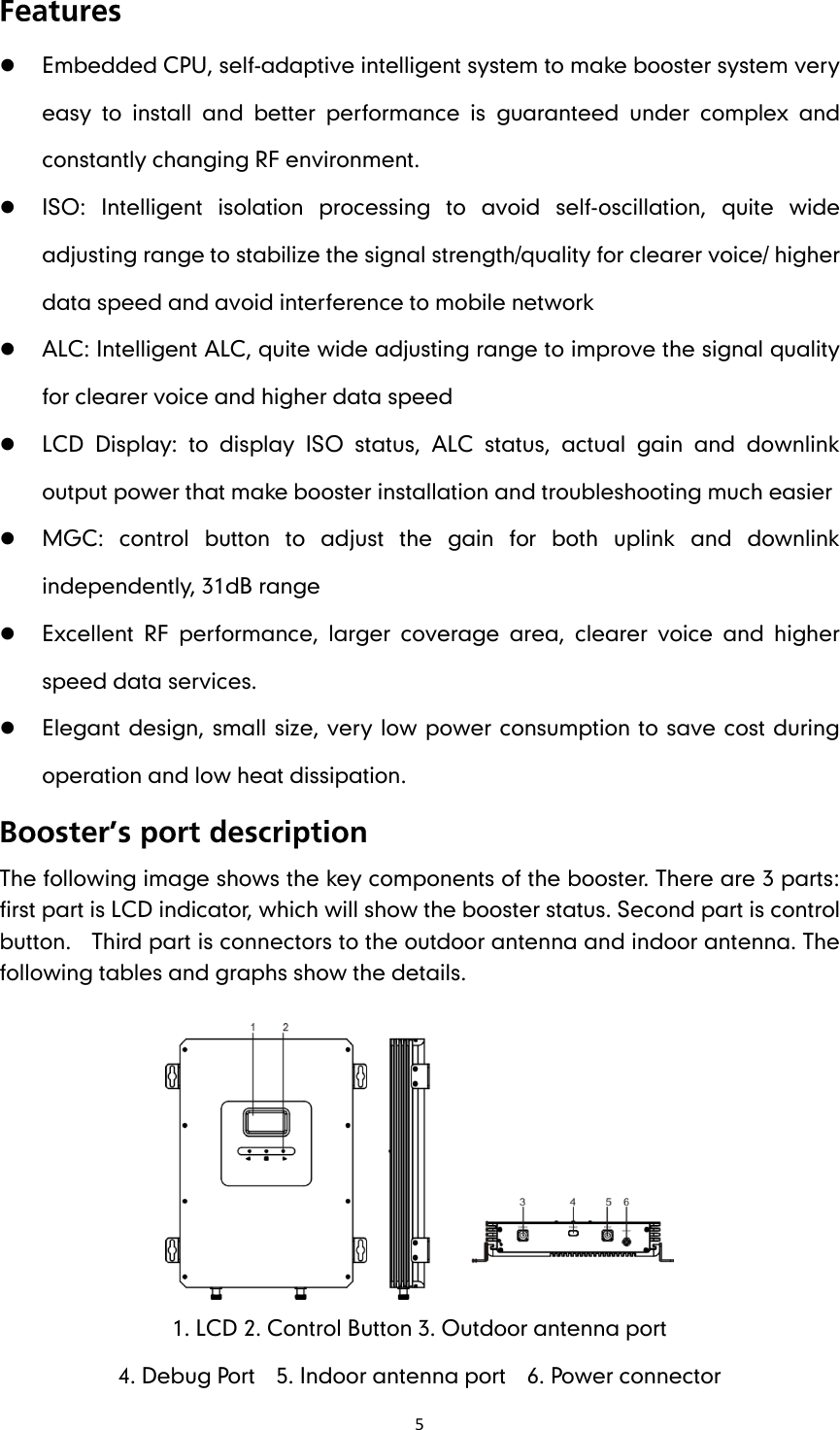
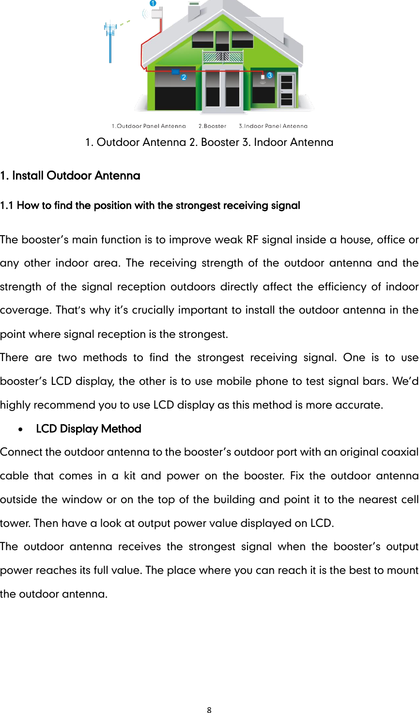
User Manual
Discussion / Help
Navigation