HON HAI PRECISION IND T60N87100 802.11 b/g Mini-PCI User Manual User Guide
HON HAI Precision Ind. Co., Ltd. 802.11 b/g Mini-PCI User Guide
UserManual.wiki
>
HON HAI PRECISION IND
>
T60N87100 User Manual
>
Users Manual
Contents
1.
DoC
2.
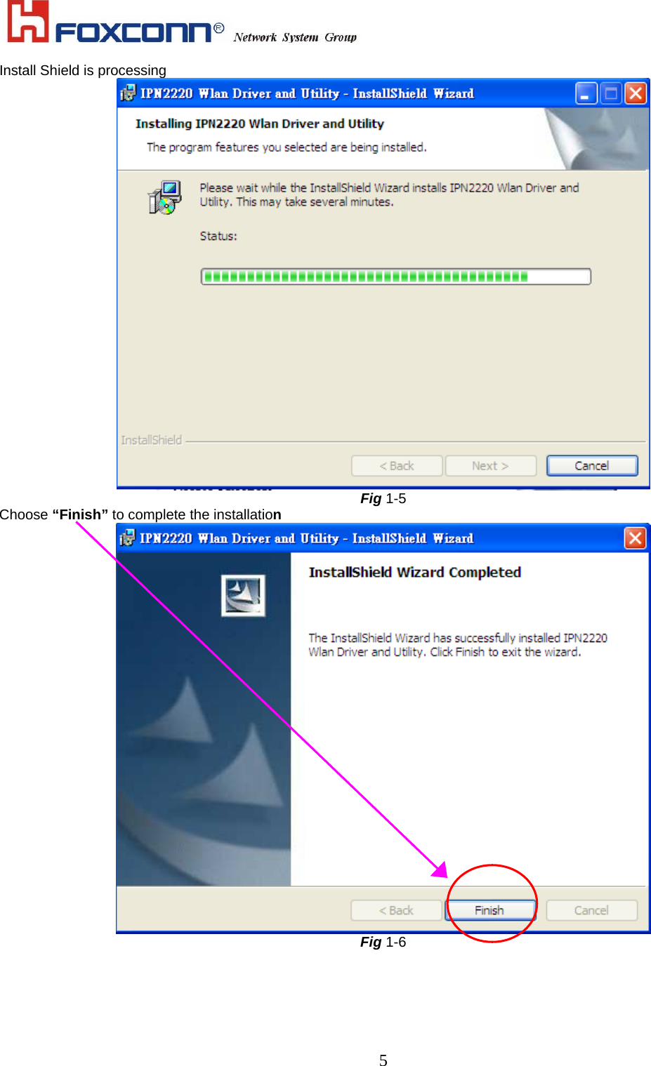
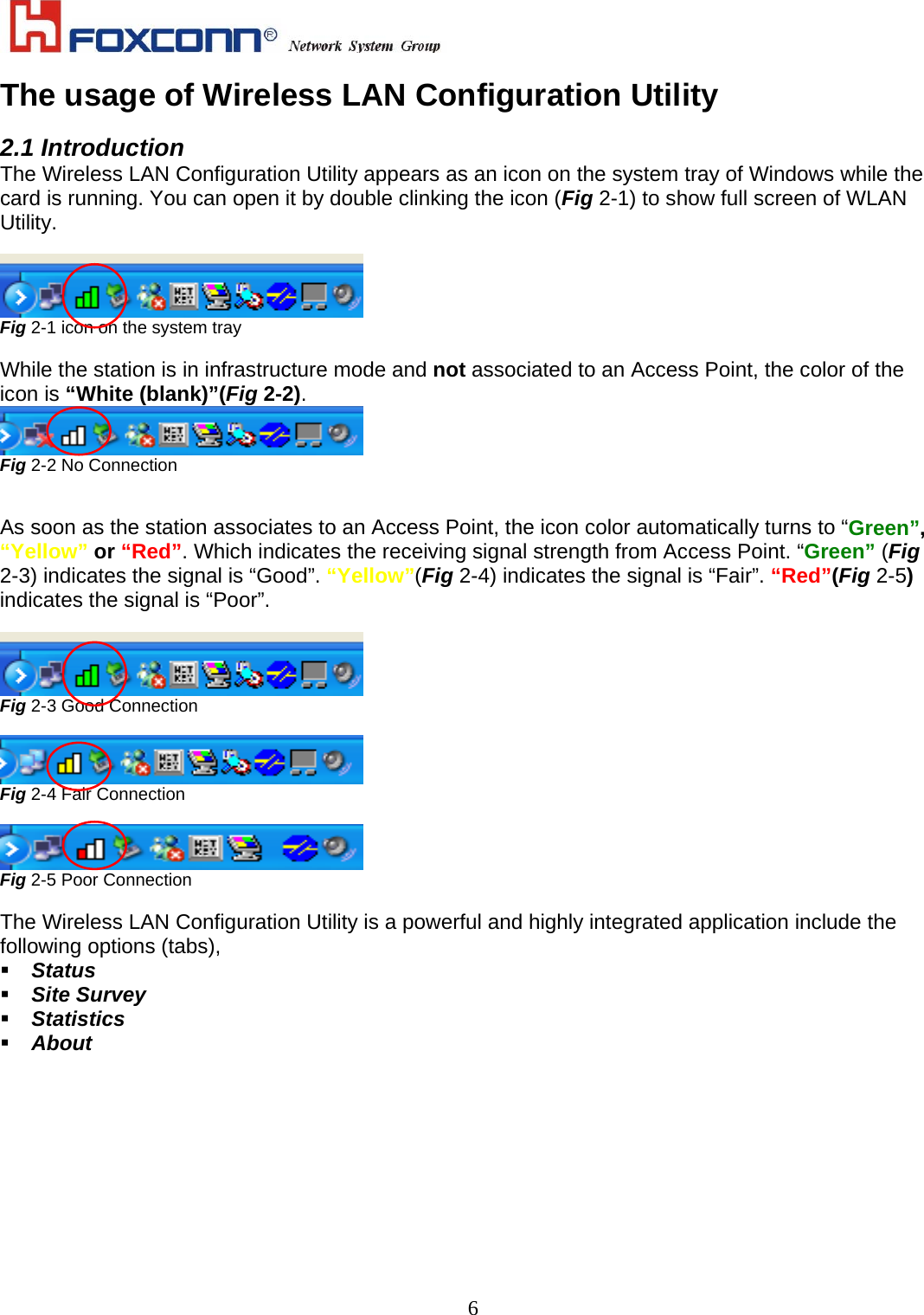
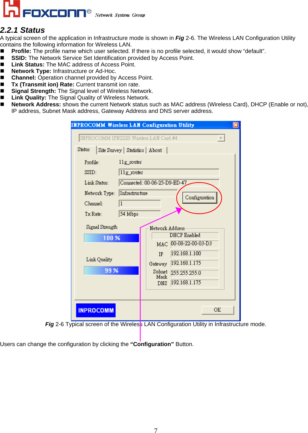
Users Manual
Users Manual
Navigation menu
Upload a User Manual
Namespaces
Wiki Guide
HTML
PDF
Info
Views
User Manual
Discussion / Help
Navigation