Glenayre Electronics GL-T8600-CN Base Station User Manual Users manual part 4
Glenayre Electronics Inc Base Station Users manual part 4
UserManual.wiki
>
Glenayre Electronics
>
GL-T8600-CN User Manual
>
Users manual part 4
Contents
1.
Users manual part 1
2.
Users manual part 2
3.
Users manuall part 3
4.
Users manual part 4
5.
Users manual part 5
Users manual part 4
Navigation menu
Upload a User Manual
Namespaces
Wiki Guide
HTML
PDF
Info
Views
User Manual
Discussion / Help
Navigation
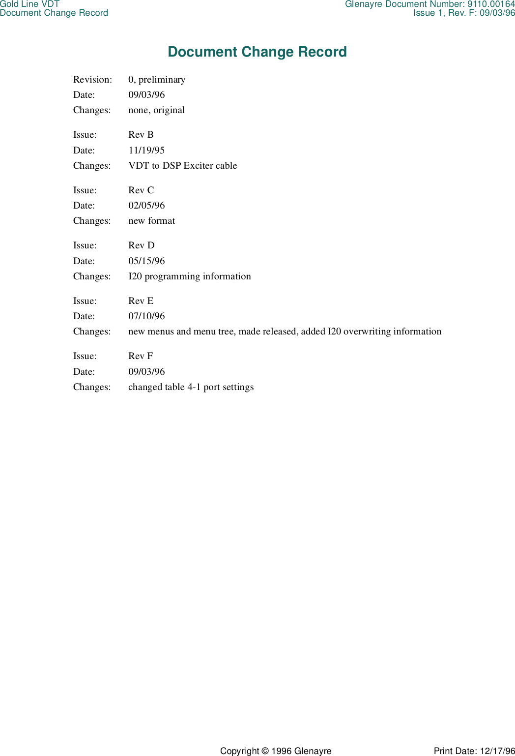
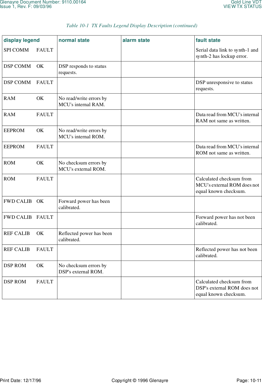
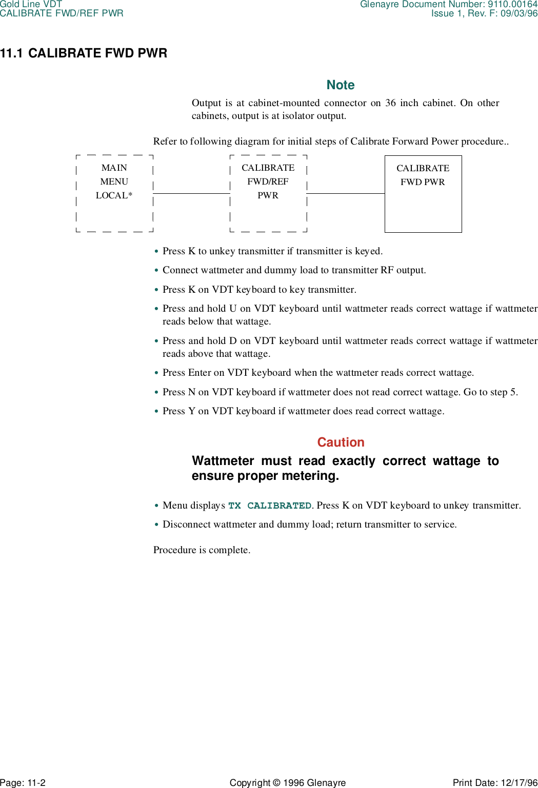
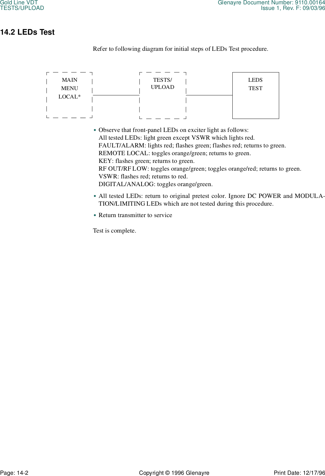
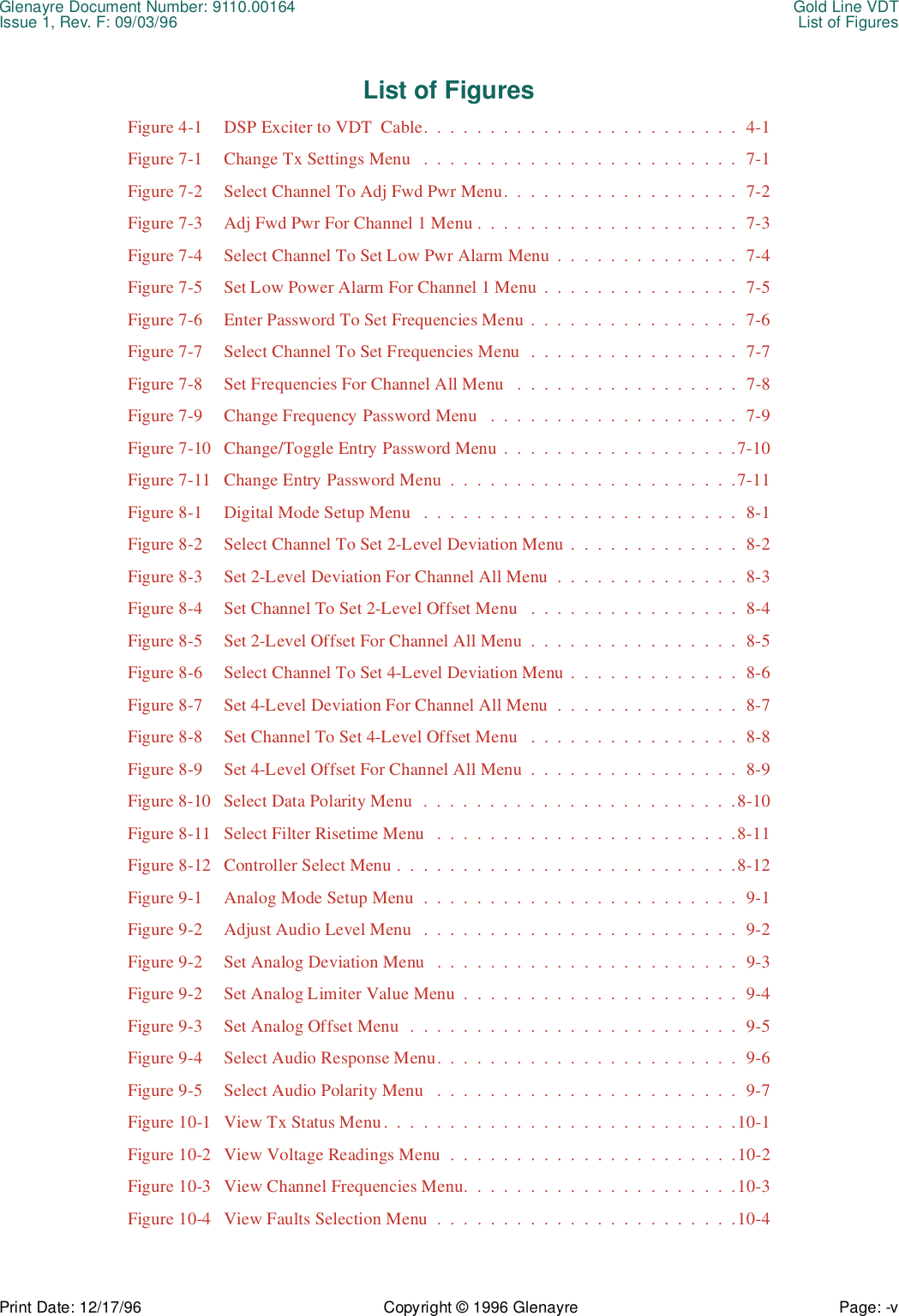
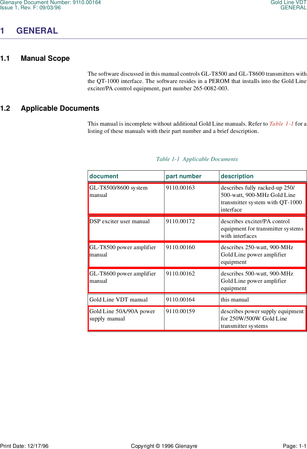
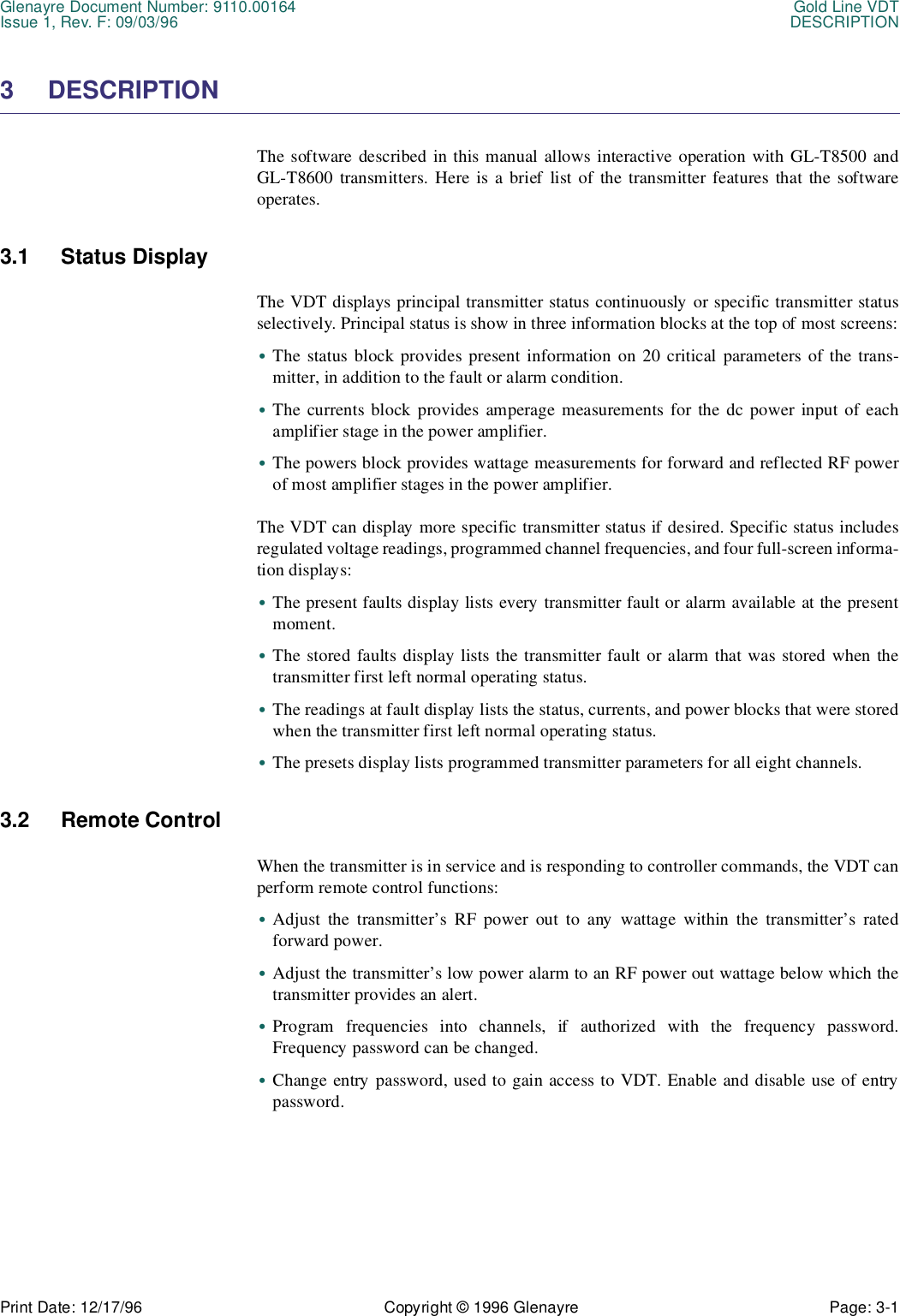
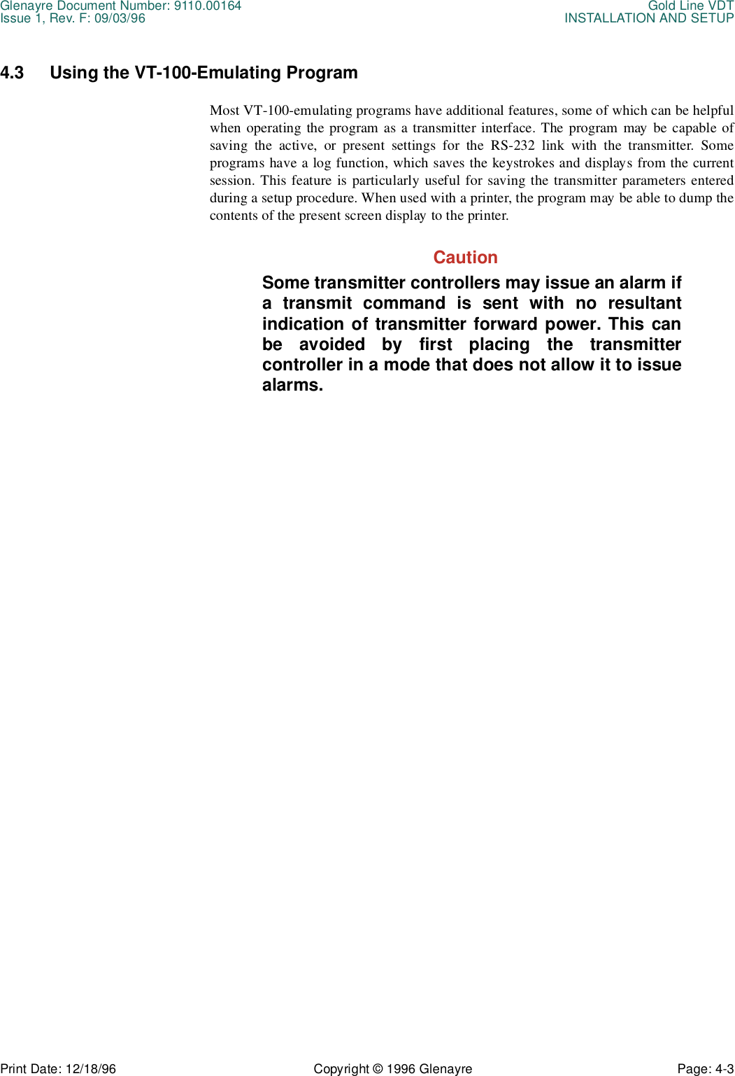
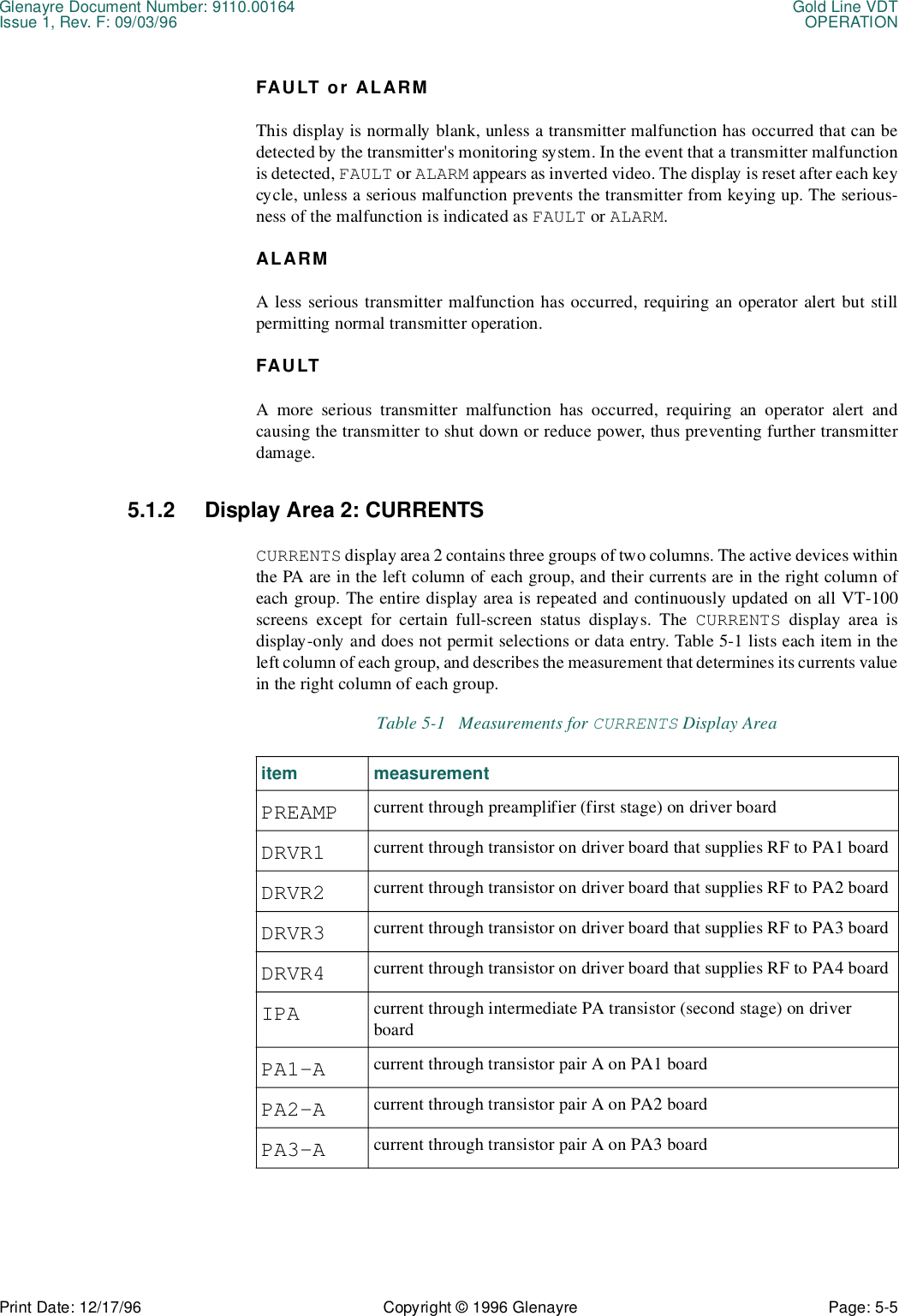
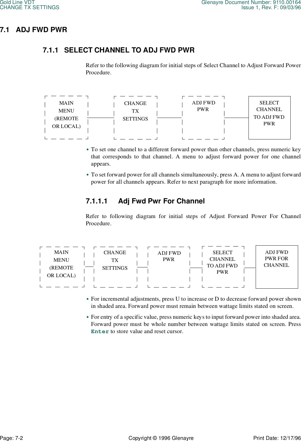
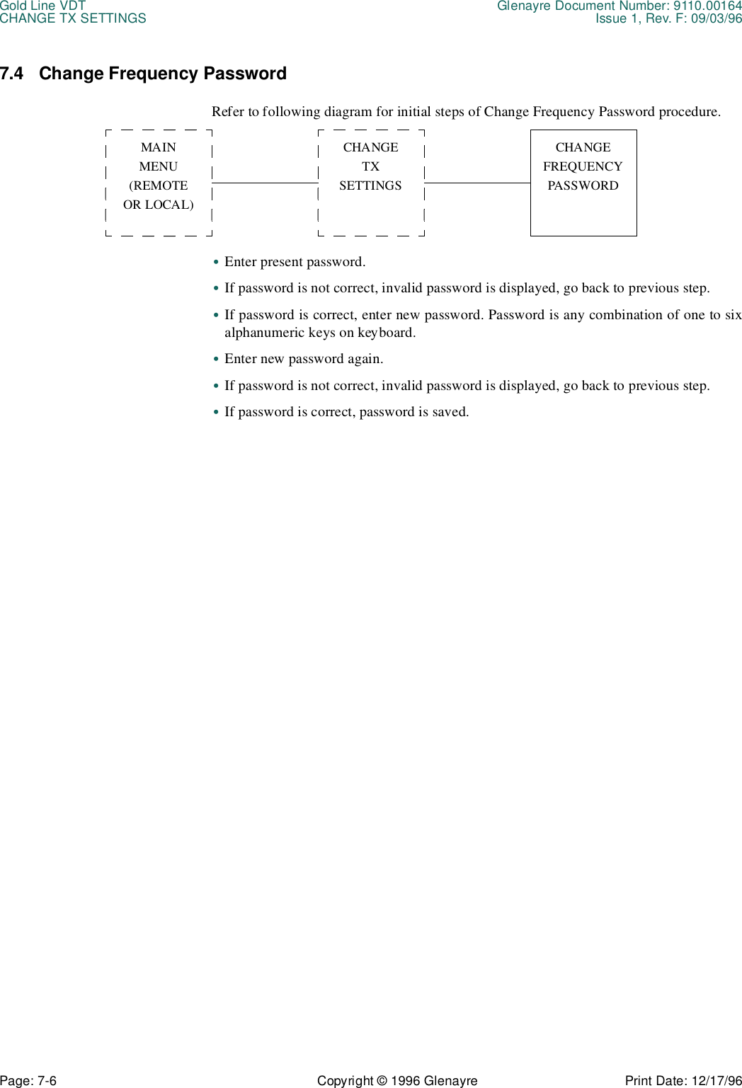
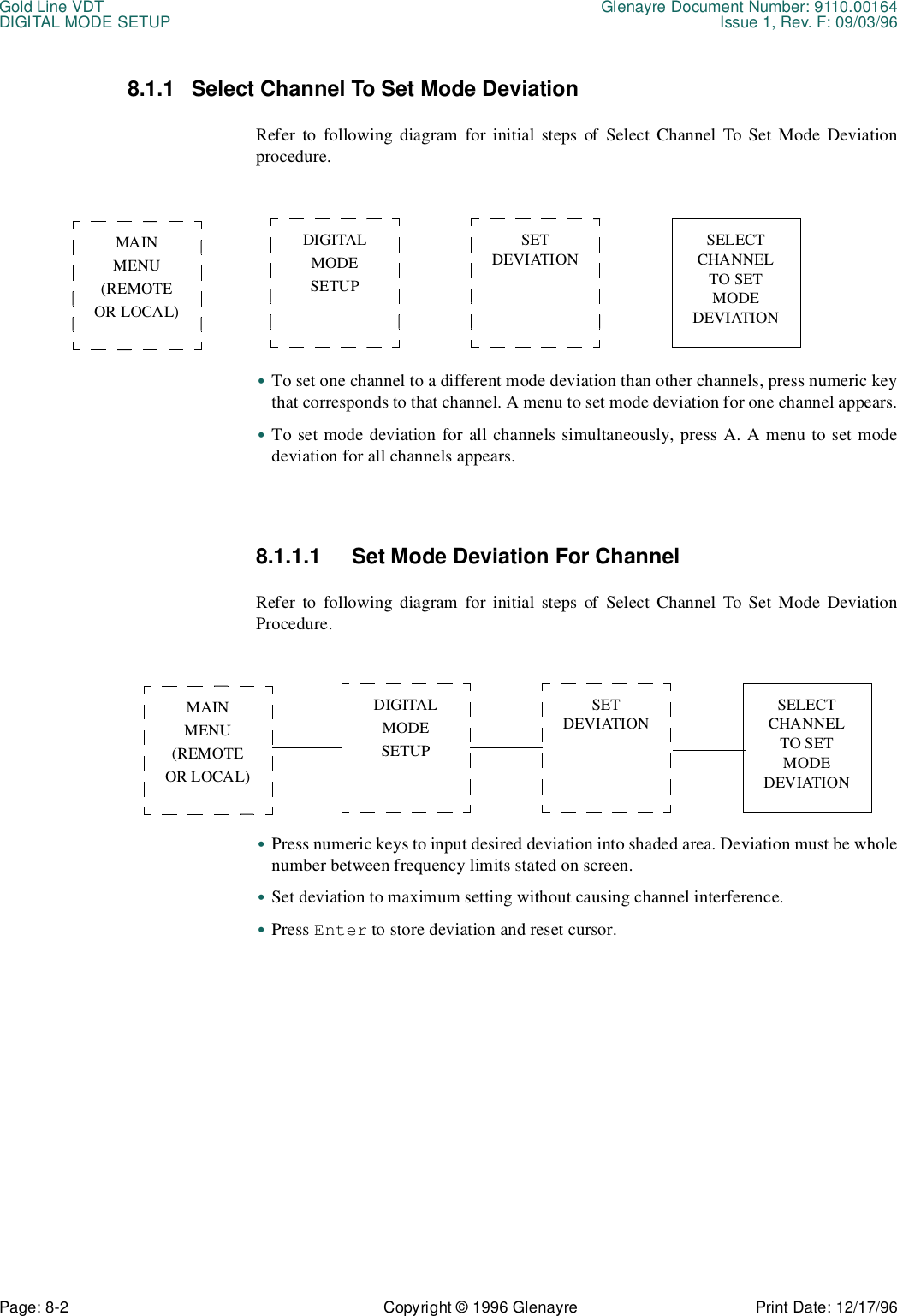
![Glenayre Document Number: 9110.00164 Gold Line VDTIssue 1, Rev. F: 09/03/96 Table of ContentsPrint Date: 12/17/96 Copyright © 1996 Glenayre Page: -i Table of Contents1 GENERAL. . . . . . . . . . . . . . . . . . . . . . . . . . . . . . . . . . . . . 1-11.1 Manual Scope . . . . . . . . . . . . . . . . . . . . . . . . 1-11.2 Applicable Documents. . . . . . . . . . . . . . . . . . . . . 1-11.3 Manual Sections . . . . . . . . . . . . . . . . . . . . . . . 1-22 REQUIREMENTS . . . . . . . . . . . . . . . . . . . . . . . . . . . . . . . . 2-12.1 VDT Requirements . . . . . . . . . . . . . . . . . . . . . . 2-12.2 Emulating Program . . . . . . . . . . . . . . . . . . . . . . 2-13 DESCRIPTION . . . . . . . . . . . . . . . . . . . . . . . . . . . . . . . . . . 3-13.1 Status Display . . . . . . . . . . . . . . . . . . . . . . . . 3-13.2 Remote Control . . . . . . . . . . . . . . . . . . . . . . . 3-13.3 Local Control . . . . . . . . . . . . . . . . . . . . . . . . 3-23.4 Setup. . . . . . . . . . . . . . . . . . . . . . . . . . . . 3-24 INSTALLATION AND SETUP . . . . . . . . . . . . . . . . . . . . . . . . . 4-14.1 VDT Connection . . . . . . . . . . . . . . . . . . . . . . . 4-14.1.1 The VDT to Exciter Interconnect Cable . . . . . . . . . . . . . .4-14.1.2 Connecting the VDT to the Transmitter . . . . . . . . . . . . . .4-24.2 Starting Up the VDT . . . . . . . . . . . . . . . . . . . . . 4-24.2.1 Presetting the Emulating Program . . . . . . . . . . . . . . . . .4-24.2.2 Access VDT Communications . . . . . . . . . . . . . . . . . . .4-24.2.3 Changing Passwords . . . . . . . . . . . . . . . . . . . . . . . .4-24.3 Using the VT-100-Emulating Program . . . . . . . . . . . . . . 4-35 OPERATION . . . . . . . . . . . . . . . . . . . . . . . . . . . . . . . . . . . 5-15.1 VT-100 Screen Displays . . . . . . . . . . . . . . . . . . . . 5-15.1.1 Display Area 1: STATUS. . . . . . . . . . . . . . . . . . . . . .5-15.1.2 Display Area 2: CURRENTS . . . . . . . . . . . . . . . . . . . .5-55.1.3 Display Area 3: POWERS . . . . . . . . . . . . . . . . . . . . .5-65.1.4 Display Area 4:Menu . . . . . . . . . . . . . . . . . . . . . . . .5-75.2 Keyboard Operation . . . . . . . . . . . . . . . . . . . . . . 5-75.2.1 Numeric Keys . . . . . . . . . . . . . . . . . . . . . . . . . . . .5-75.2.2 Enter/Return Key . . . . . . . . . . . . . . . . . . . . . . . . . .5-75.2.3 [Esc]. . . . . . . . . . . . . . . . . . . . . . . . . . . . . . . . .5-85.2.4 Alphabetic Function Keys . . . . . . . . . . . . . . . . . . . . .5-86 MENU TREE . . . . . . . . . . . . . . . . . . . . . . . . . . . . . . . . . . . 6-17 CHANGE TX SETTINGS . . . . . . . . . . . . . . . . . . . . . . . . . . . . 7-17.1 Select Channel To Adj Fwd Pwr . . . . . . . . . . . . . . . . . 7-2](https://usermanual.wiki/Glenayre-Electronics/GL-T8600-CN.Users-manual-part-4/User-Guide-12766-Page-3.png)
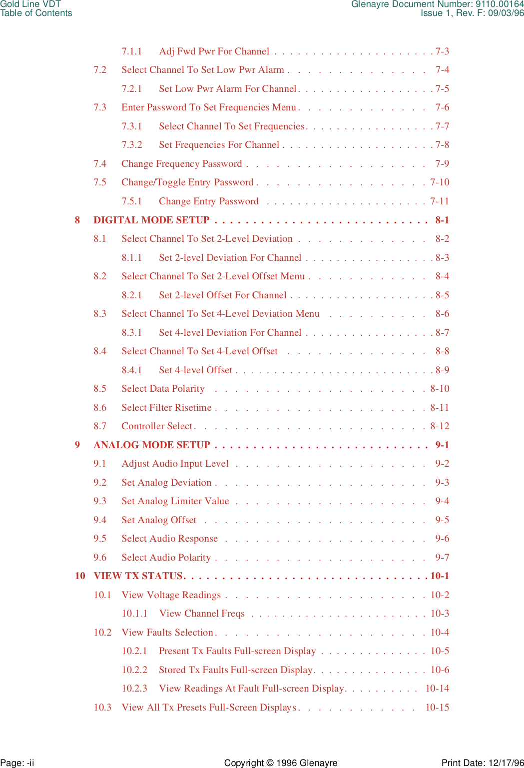
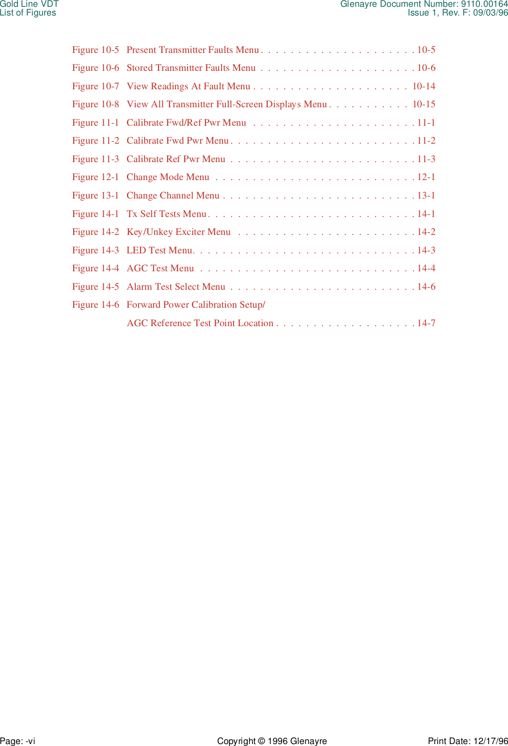
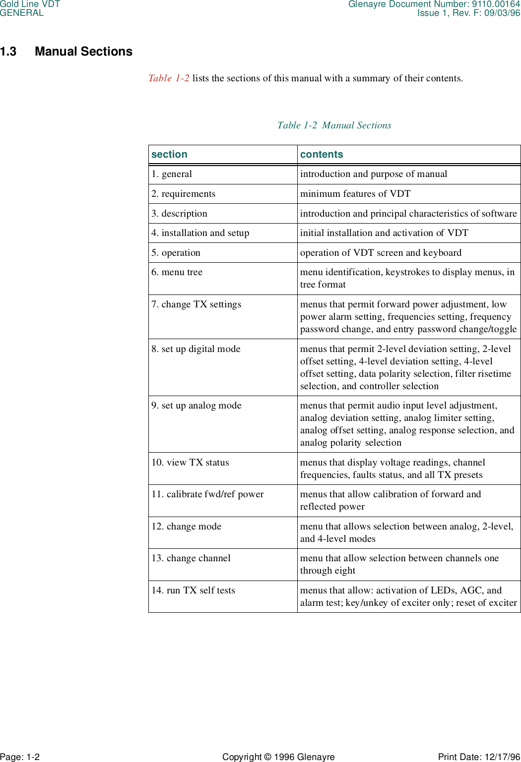
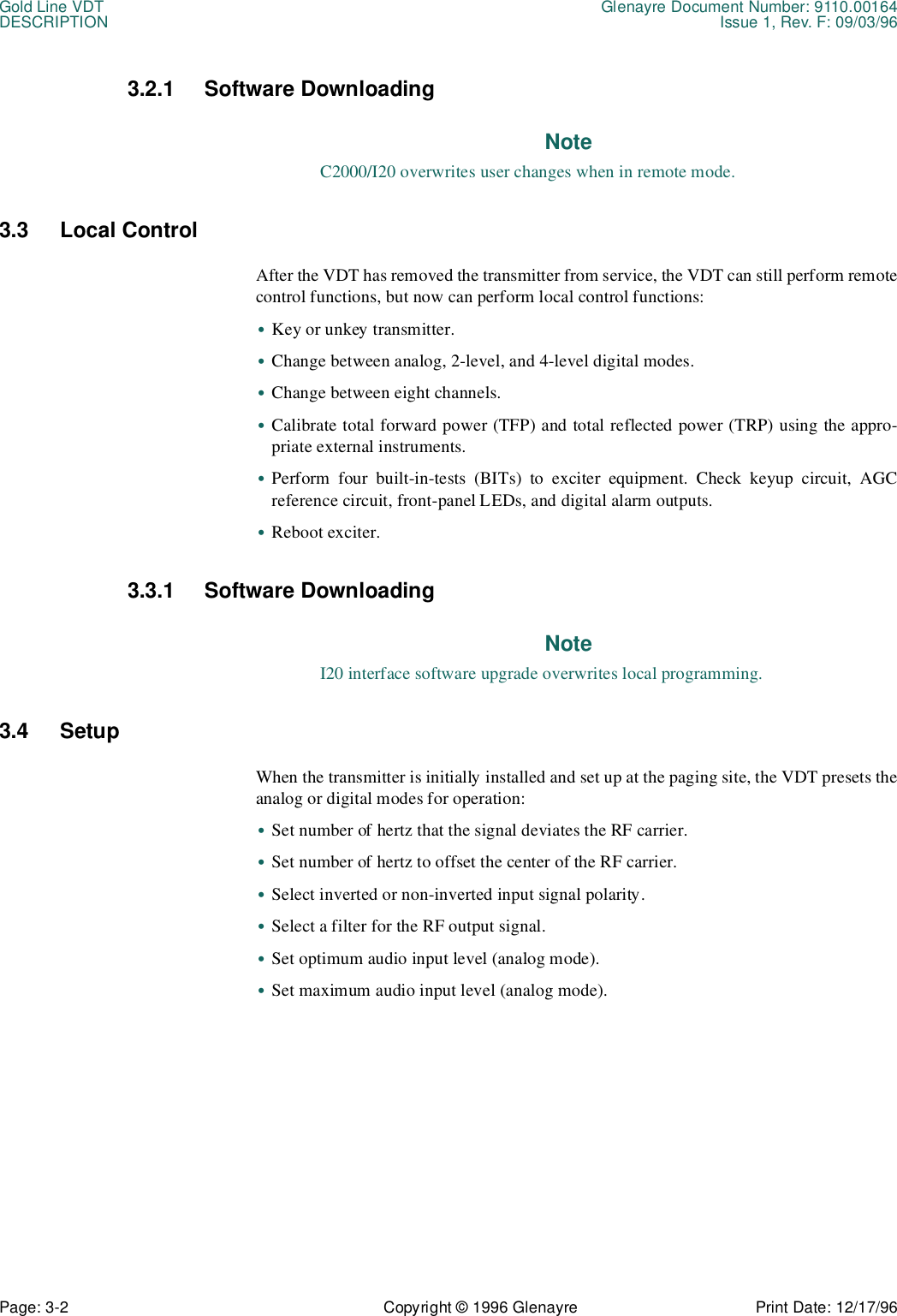

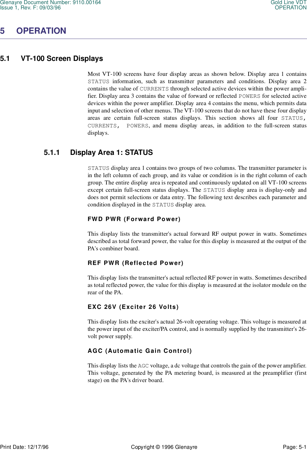
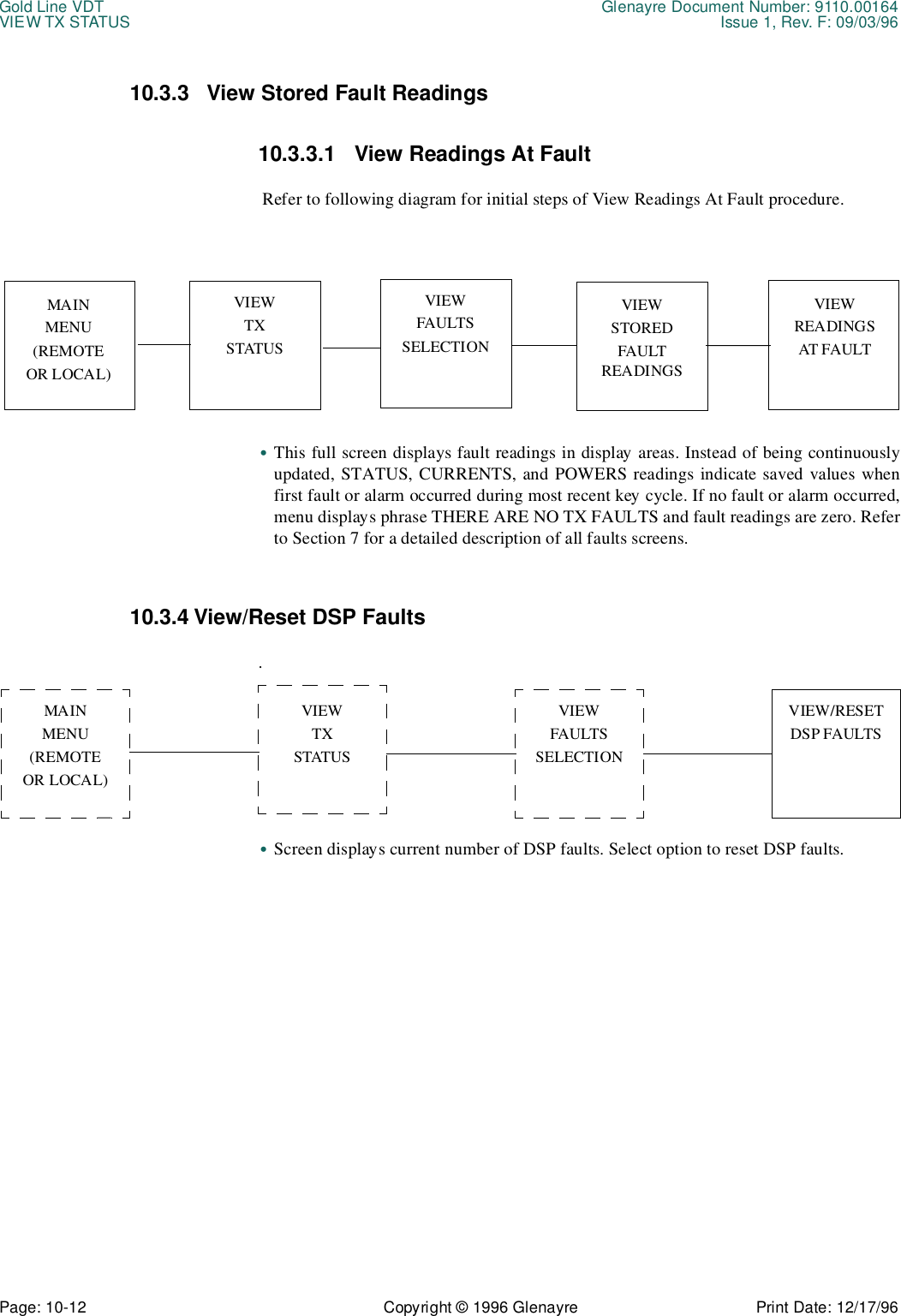
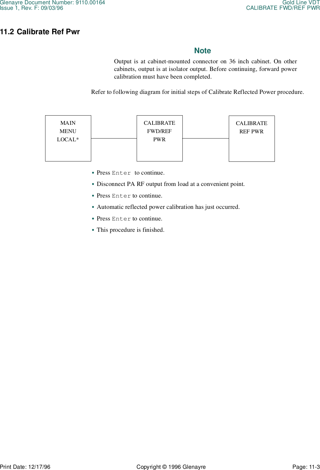
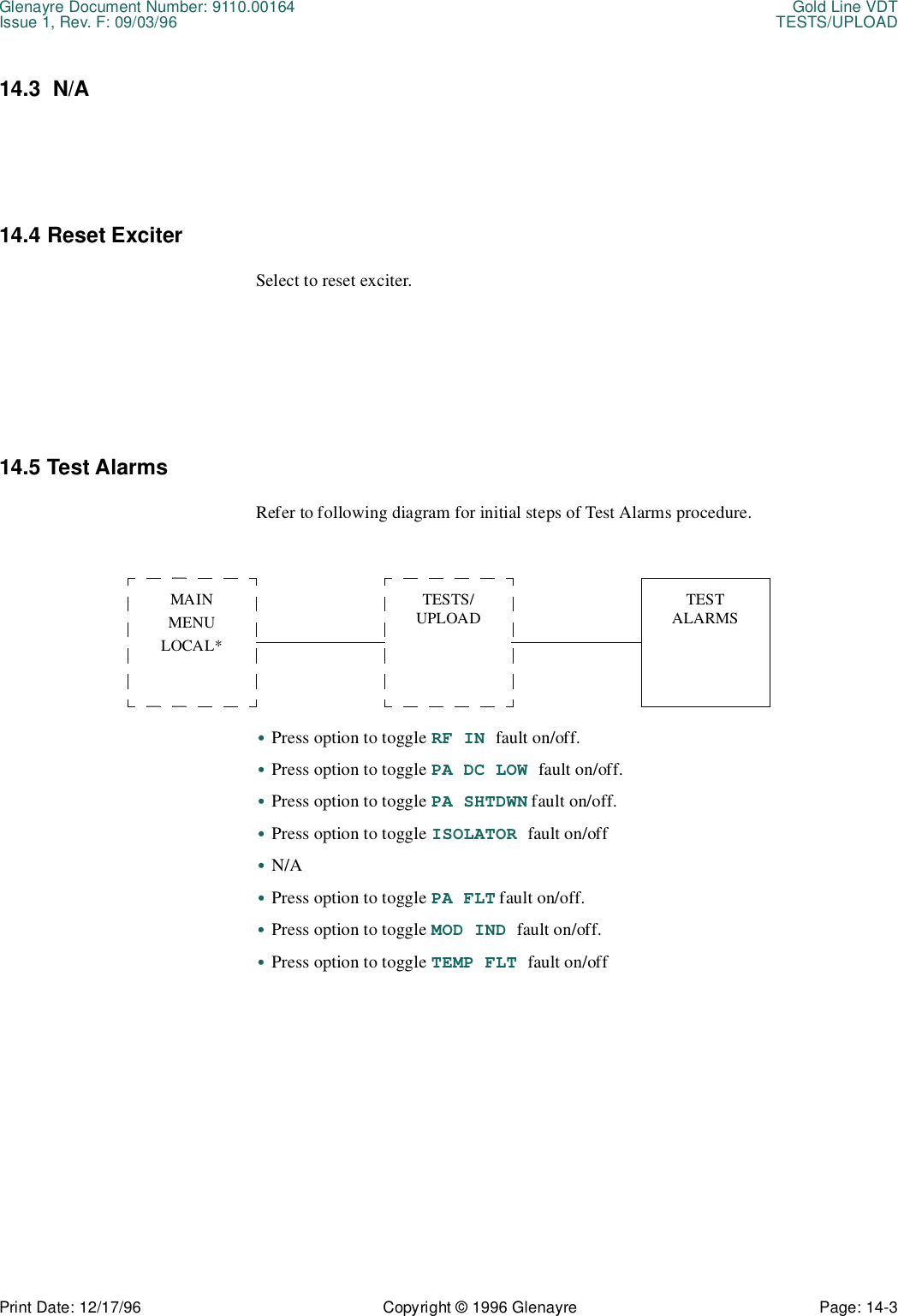
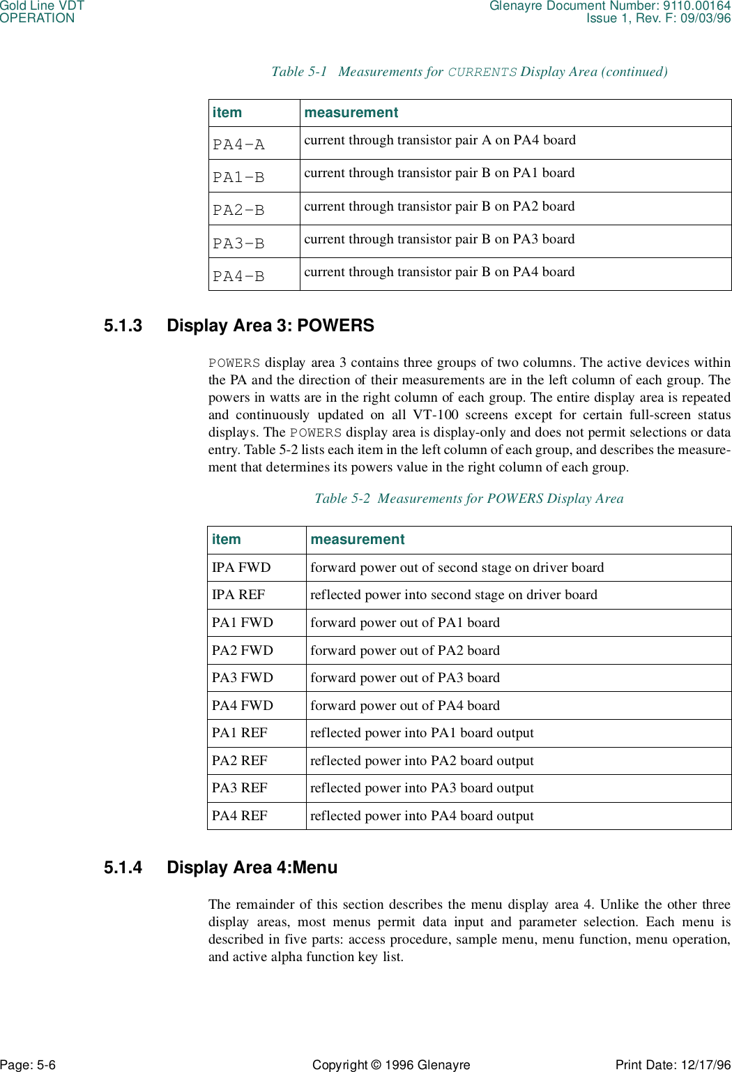
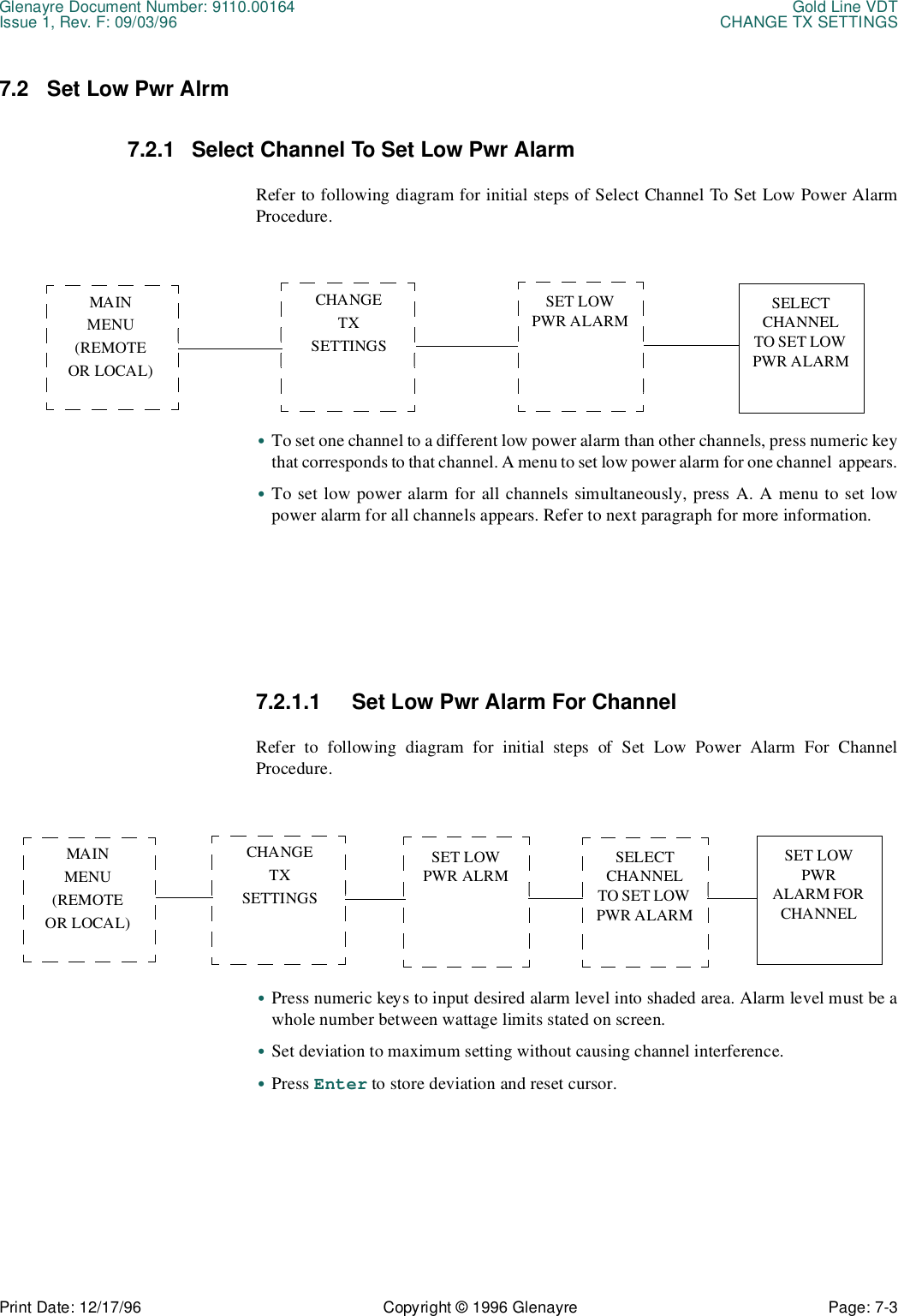
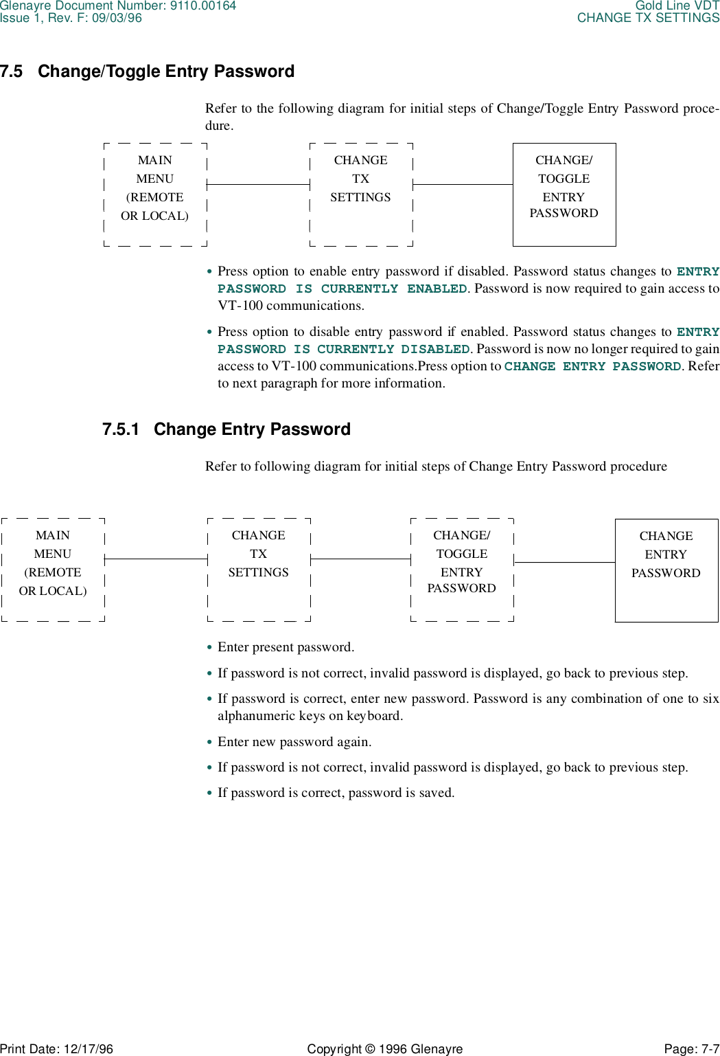
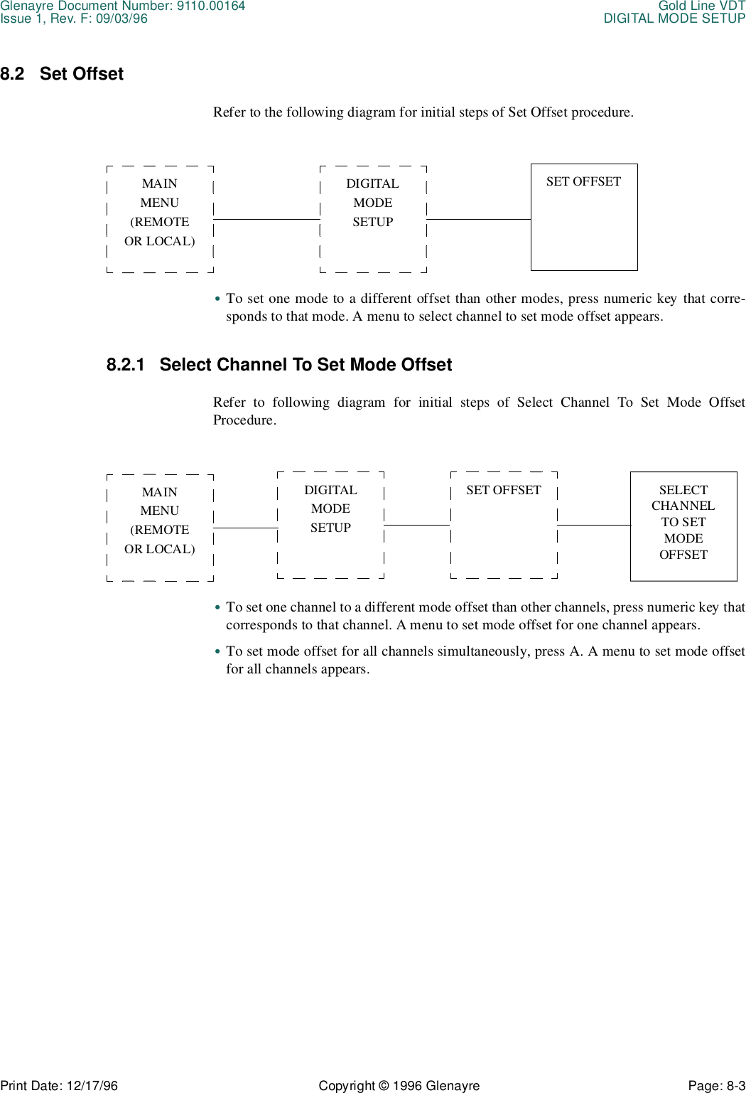
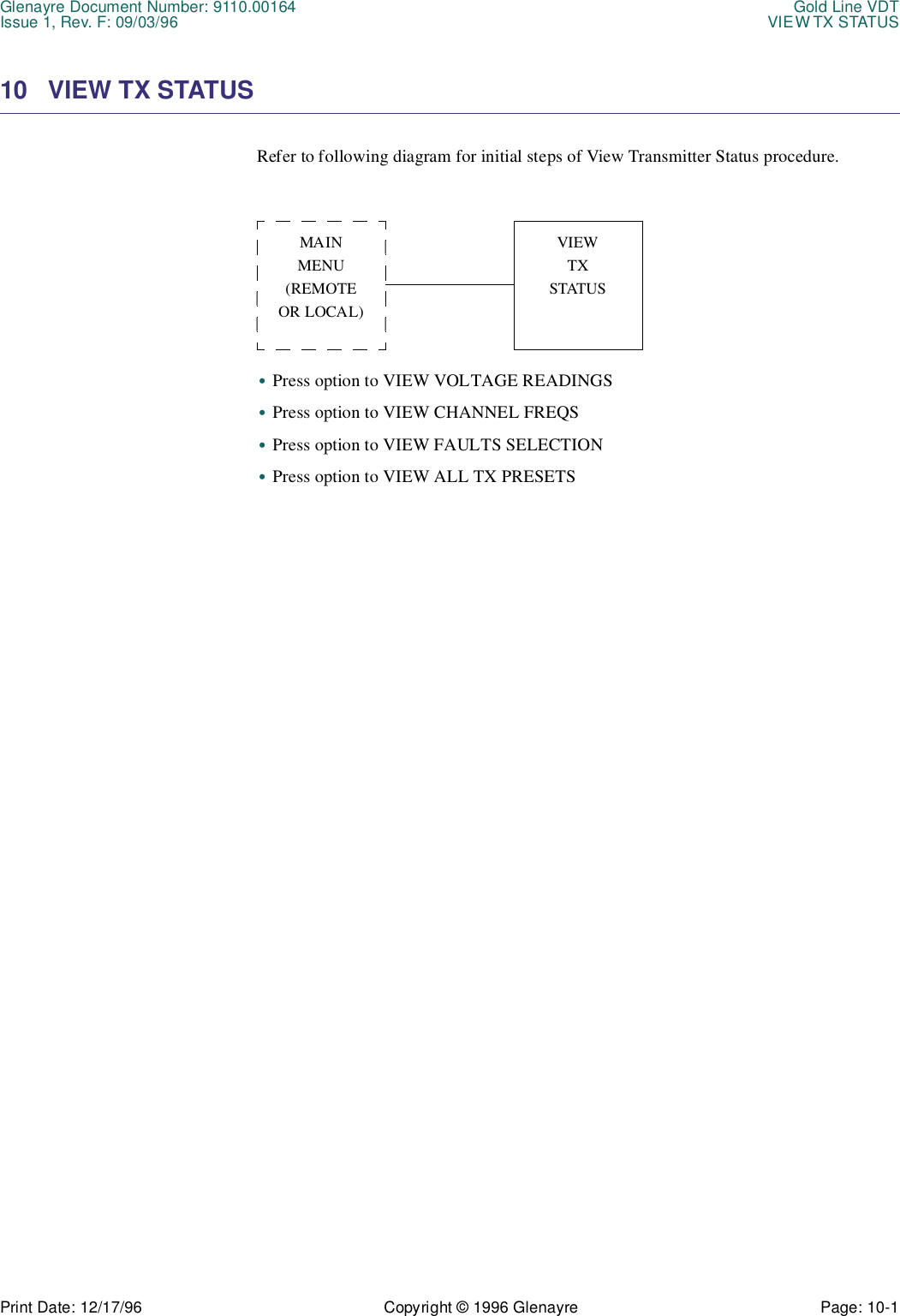
![Gold Line VDT Glenayre Document Number: 9110.00164OPERATION Issue 1, Rev. F: 09/03/96Page: 5-4 Copyright © 1996 Glenayre Print Date: 12/17/96DATA POL (Polarity)•When in 2-level FSK mode and NON-INV is listed_, data "1" generates a frequencyabove f0 and data "0" generates a frequency below f0.•When in 2-level FSK mode and INV is listed, data "1" generates frequency below f0 anddata "0" generates a frequency above f0.•When in 4-level FSK mode and NON-INV is listed, data "10" and data "11" generatefrequencies above f0. Data "01" and data "00" generate frequencies below f0.•When in 4-level FSK mode and INV is listed, data "10" and data "11" generate frequen-cies below f0. Data "01" and data "00" generate frequencies above f0. Note that data isrearranged, not just inverted (3-4/2-1 to 2-1/4-3).ANLG POL (analog polarity)•When in analog mode and NON-INV is listed, a positive voltage into audio (+) causes apositive deviation from f0 and a negative voltage into audio (+) causes a negativedeviation from f0.•When in analog mode and INV is listed, a positive voltage into audio (+) causes anegative deviation from f0 and a negative voltage into audio (+) causes a positivedeviation from f0.CONTROLThis display lists the transmitter's presently selected control state. This state is listed eitheras LOCAL or REMOTE.•REMOTE - this is the transmitter's normal operating mode. External control inputs suchas channel, mode, and key commands are supplied by a device such as a transmittercontroller and are obeyed by the transmitter. These commands are not possible throughthe VT-100 interface when in the remote control mode.•LOCAL - this is the transmitter's maintenance mode. External control inputs such aschannel, mode, and key commands are ignored by the transmitter. These commands, inaddition to maintenance, setup, and self test functions, are possible through the VT-100interface when in the local control mode.KEY STATEThis display lists the transmitter's presently selected key input state. This state is listed asKEYED or UNKEYED. The logic for this condition is detected in the exciter/PA control. Akeyed condition indicates an external key hardline activation (in the remote control mode)or a VT-100 VDT [K] key software selection (in the local control mode).FILTERThis display lists the rise time, in microseconds, of the presently selected digital premodu-lation filter. This rise time is effective for the digital FSK modes only, although it is alwaysdisplayed regardless of mode.CHAN BW (Channel Bandwidth)This display lists maximum bandwidth, in kHz, of all the transmitter channels. Thebandwidth is determined by the filtering circuitry installed in the exciter/PA control.](https://usermanual.wiki/Glenayre-Electronics/GL-T8600-CN.Users-manual-part-4/User-Guide-12766-Page-24.png)
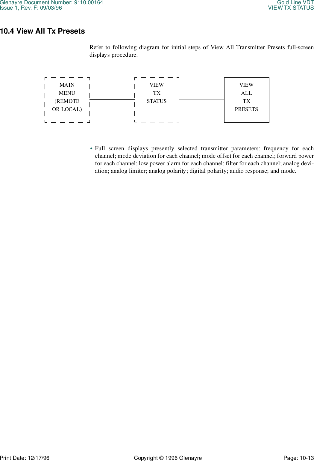
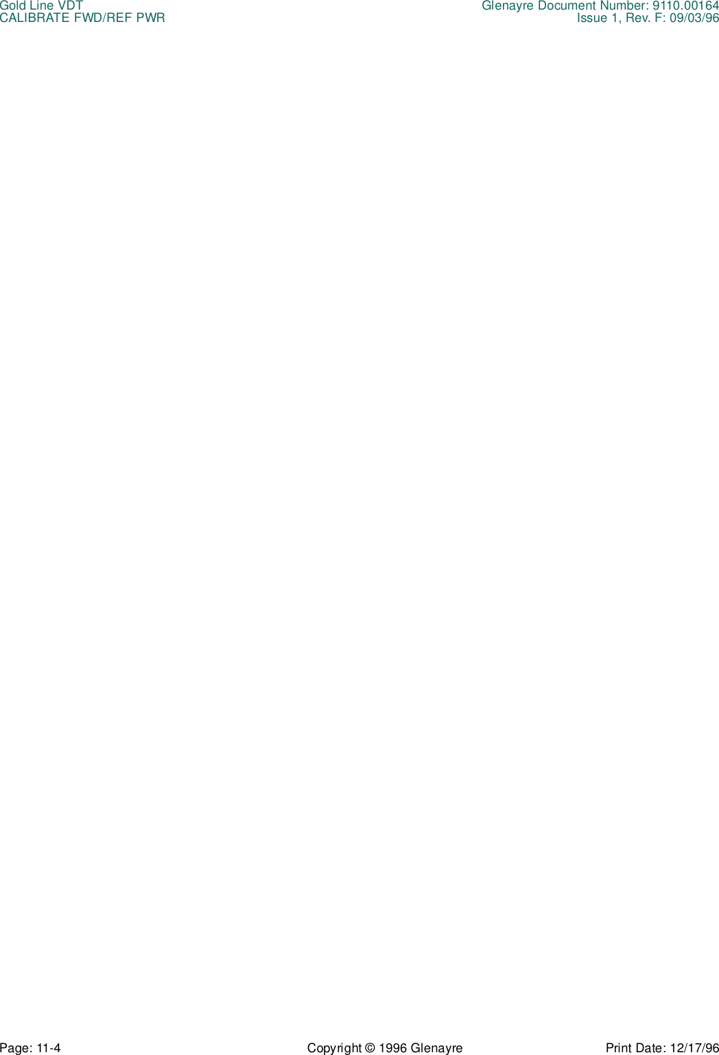
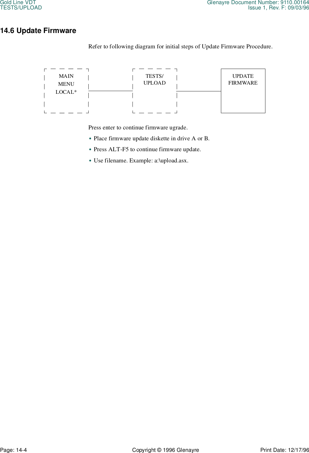
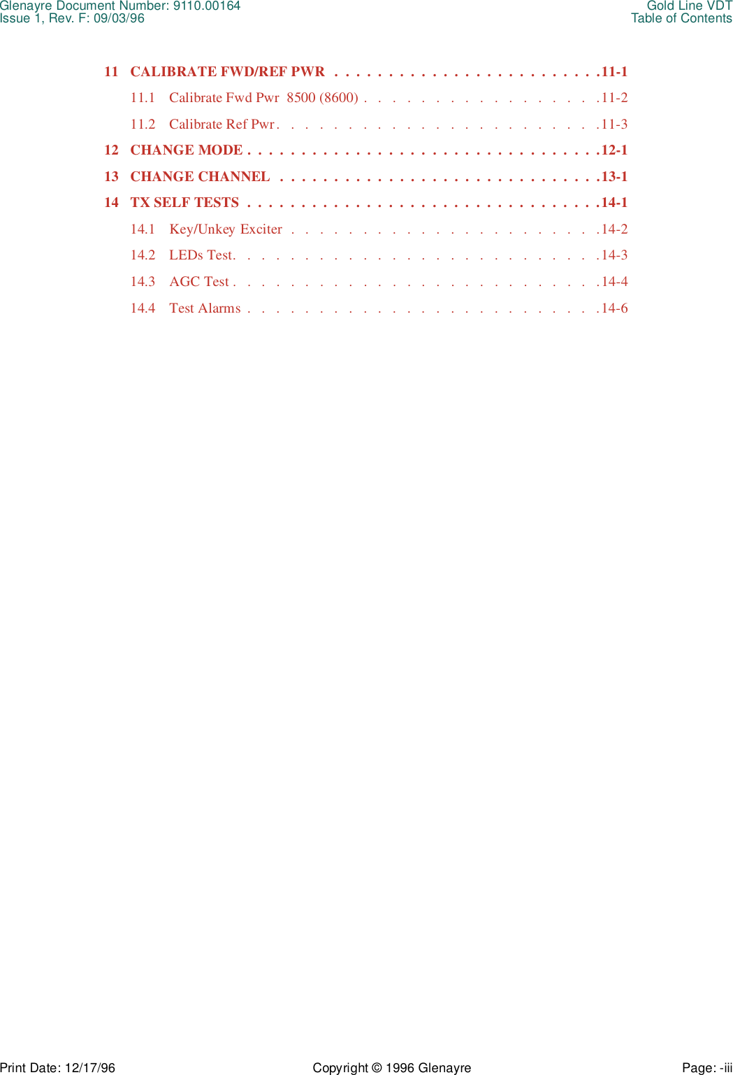
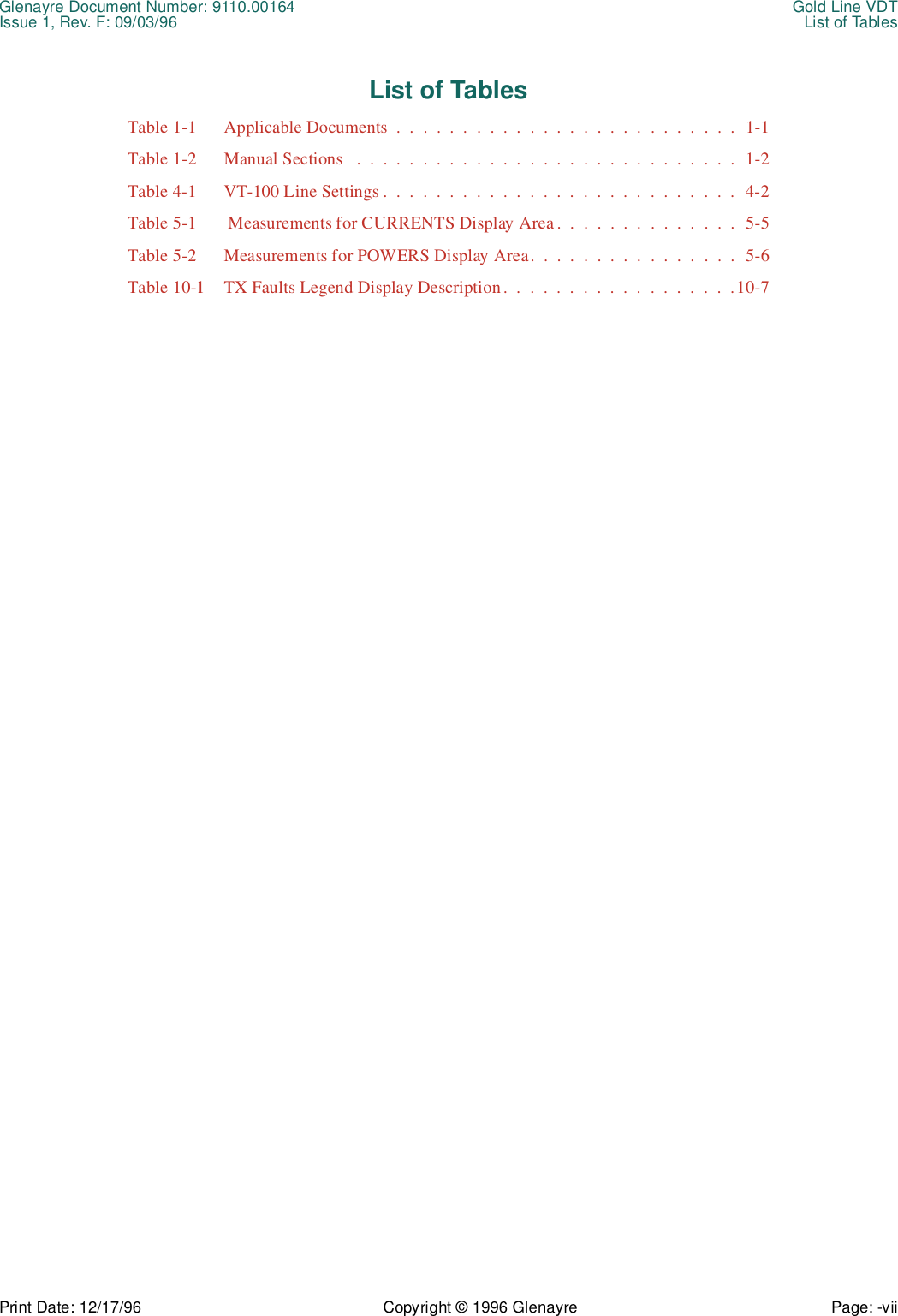
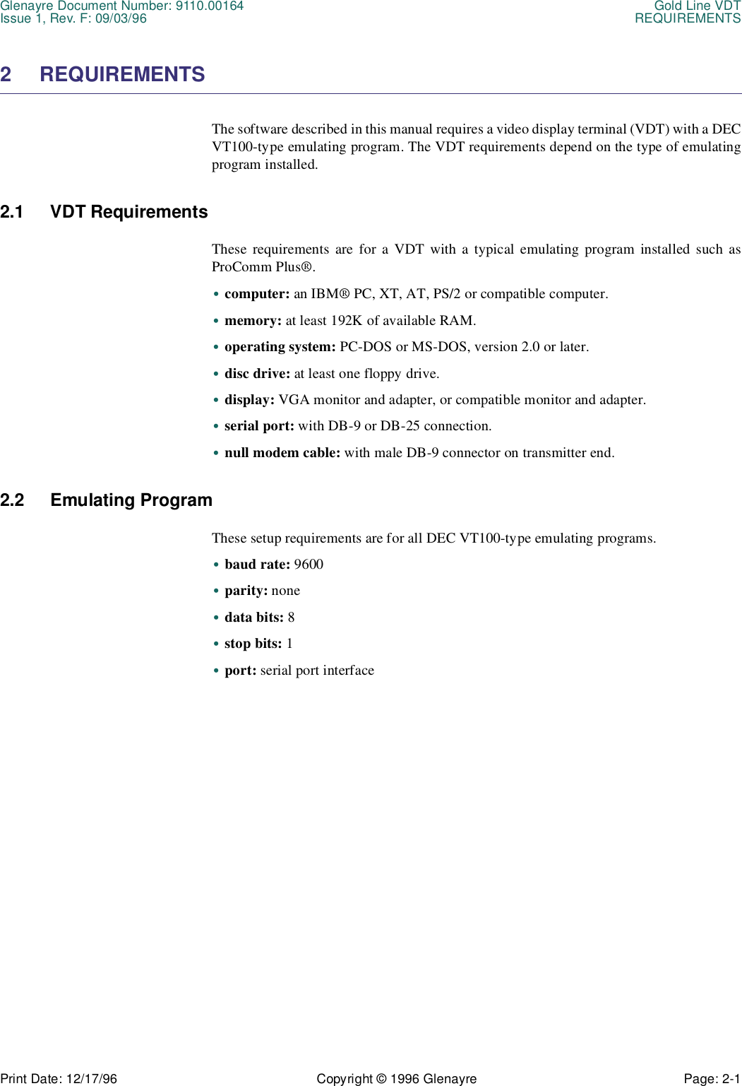
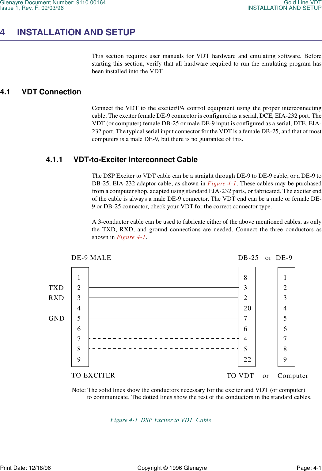
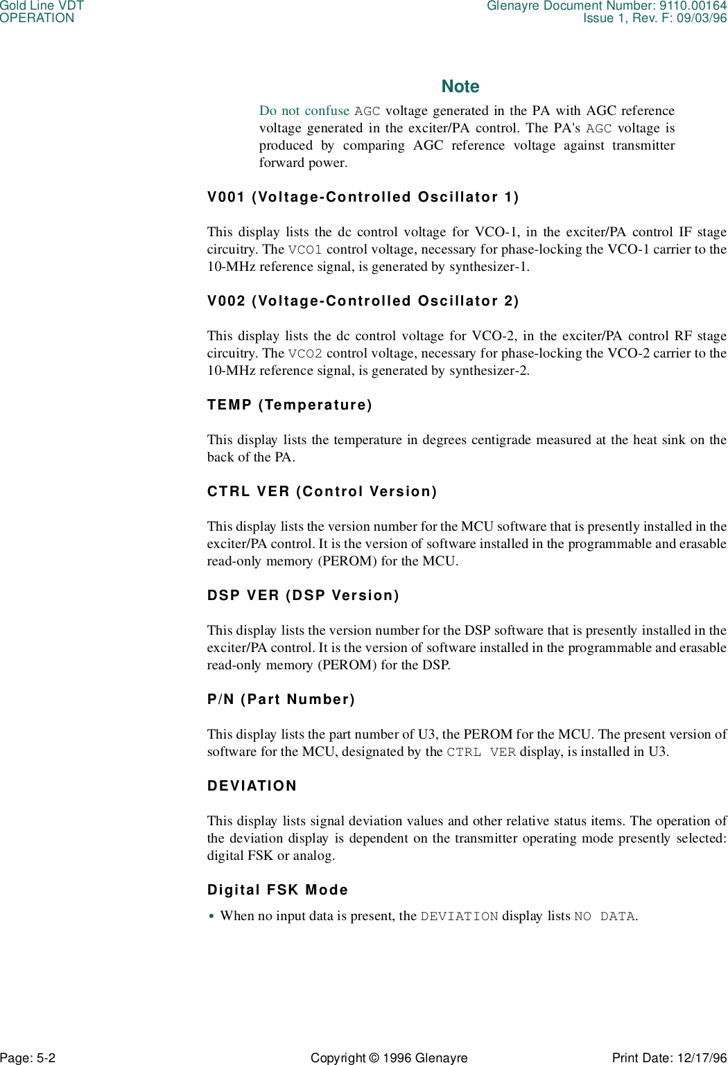
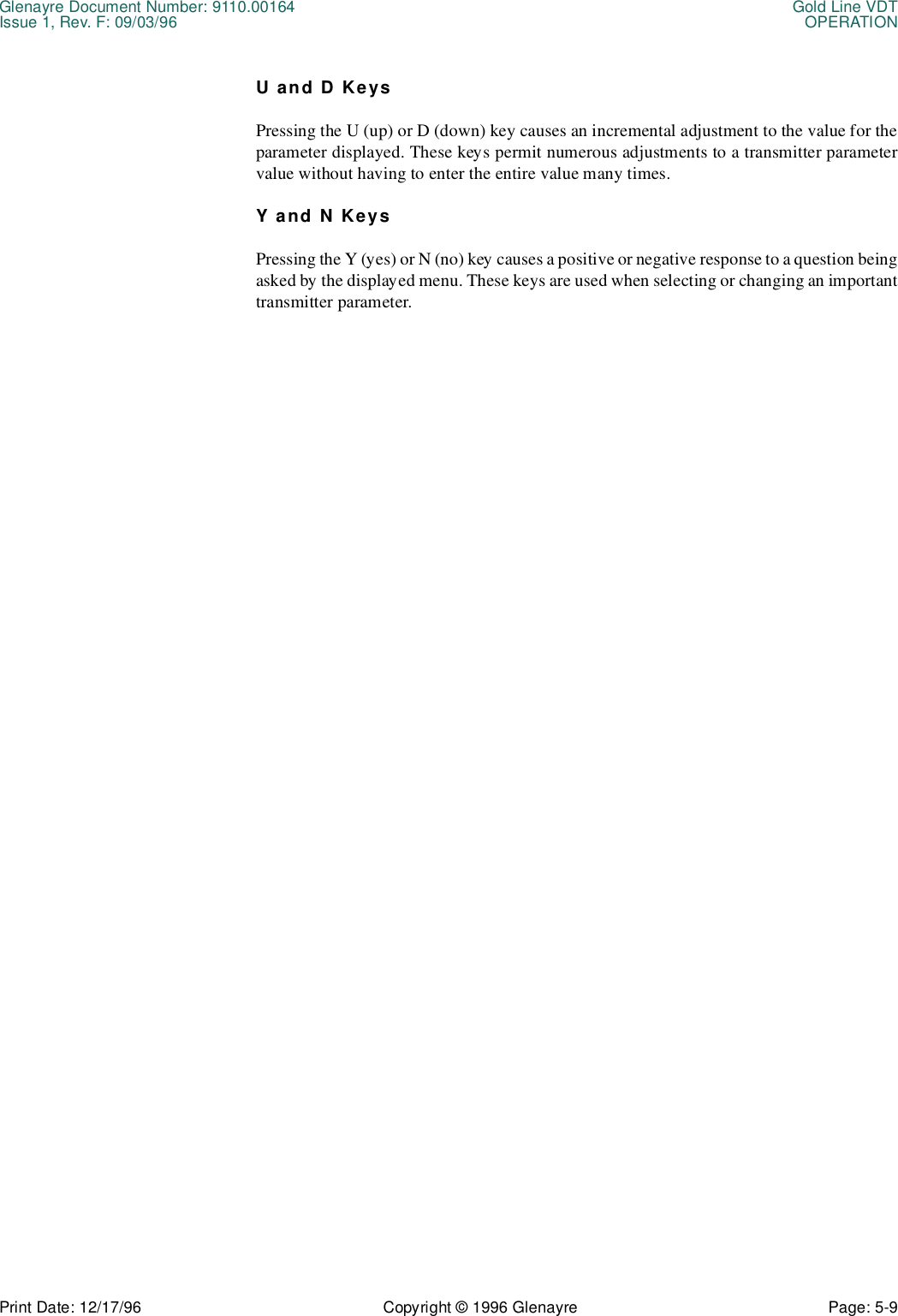
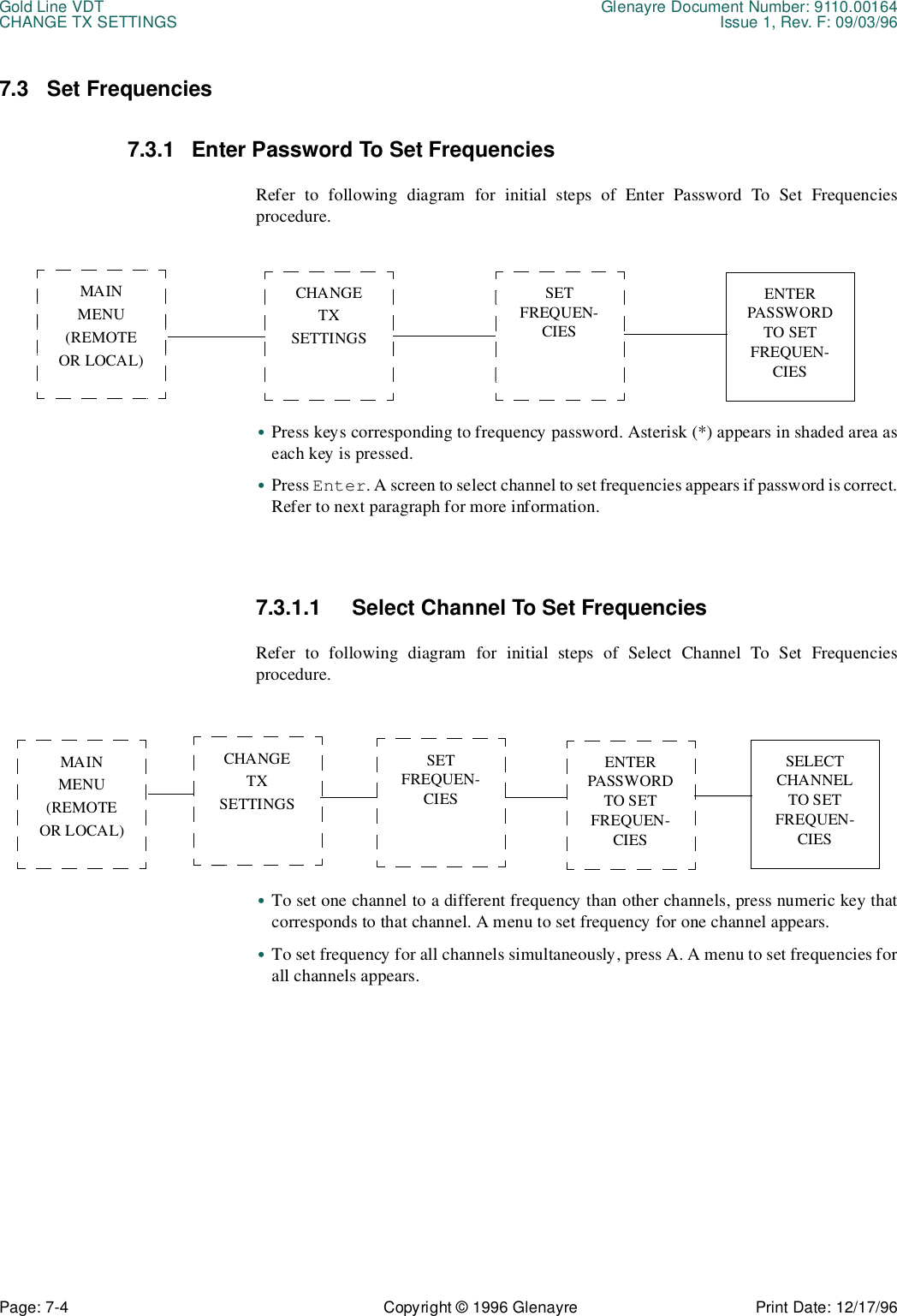
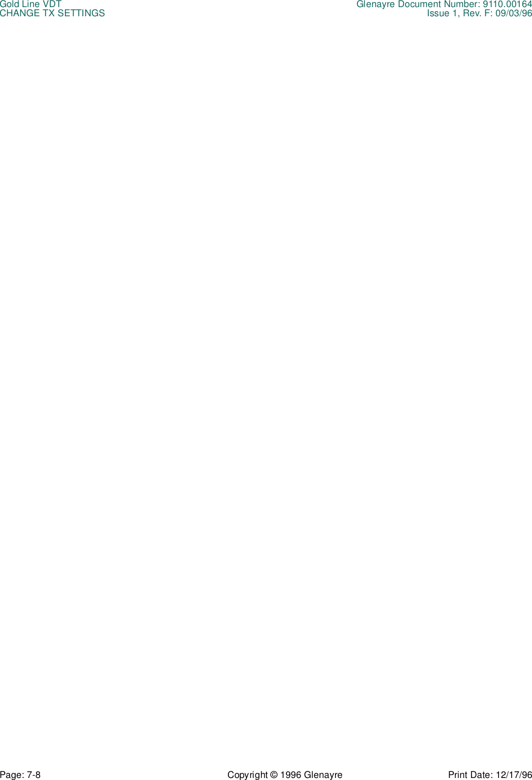
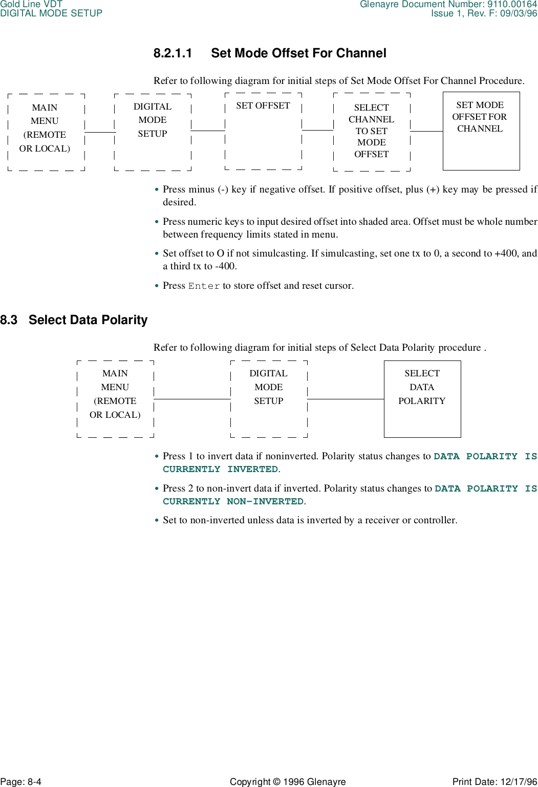
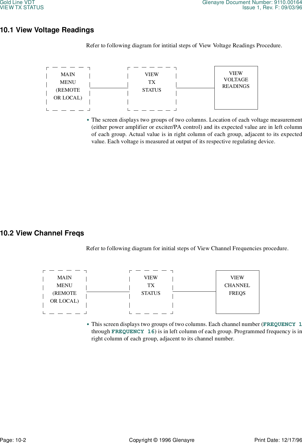
![Glenayre Document Number: 9110.00164 Gold Line VDTIssue 1, Rev. F: 09/03/96 OPERATIONPrint Date: 12/17/96 Copyright © 1996 Glenayre Page: 5-7 1. Access Procedure - an access procedure is included at the top of each page just be-low the menu title. The access procedure describes the keystrokes or other actions re-quired to display this menu.2. Sample Menu - a sample menu is outlined by a square. This sample shows the typical contents of display area 4 when the menu is selected.3. Menu Function - a menu function describes the purpose of the menu.4. Menu Operation - a menu operation describes how to use the menu.5. Active Alpha Function Keys - an active alpha function key list is at the bottom of each page. This list contains the alphabetical keys, active when the menu is displayed, that have been assigned a predetermined software function. The predetermined soft-ware function of these alpha keys is described in the previous introductory Section 4.5.2 Keyboard OperationDepending upon the displayed menu, the keys most often used on the keyboard are thenumeric keys, enter/return key, [ESC], and alphabetic function keys. 5.2.1 Numeric KeysThe numeric keys are used to select a menu or transmitter parameter, or to enter a value intoa data input field. The numeric keys on the keypad function identically to those on the mainkeyboard if [NUM LOCK] is enabled.If the menu contains a list of numbered options, a single press of a numeric key producesthe menu or function desired. No further keystrokes are required if the number pressed wasone of the options.If the menu contains a data input field, more than one keystroke is usually required toproduce the desired function. Pressing numeric keys causes the value to appear in this datainput field, in the space underlined by the cursor. The backspace key is functional duringthis procedure. After typing a value into the data input field, a press of enter/return isrequired to activate the value.5.2.2 Enter/Return KeyThis key is labeled Enter, Return, or abbreviations thereof, depending upon the keyboard.This key performs the same enter function regardless of label, and so is called [ENTER].The key is used to activate a value that has been typed into a data input field.When a data input field first appears, it already contains the default value or the last valueentered by previous keystrokes. A cursor located to the left of this value indicates where atyped numeral will appear. As the new value is typed into the data input field, the old valuedisappears and the cursor flows to the right of the new value. After [ENTER] is pressed,the cursor resets to the left to indicate the new value has become the operative value.](https://usermanual.wiki/Glenayre-Electronics/GL-T8600-CN.Users-manual-part-4/User-Guide-12766-Page-27.png)
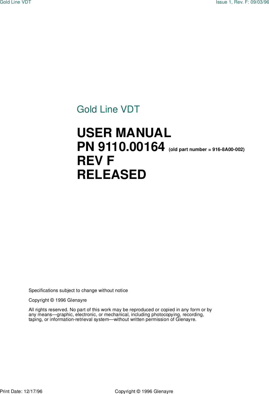
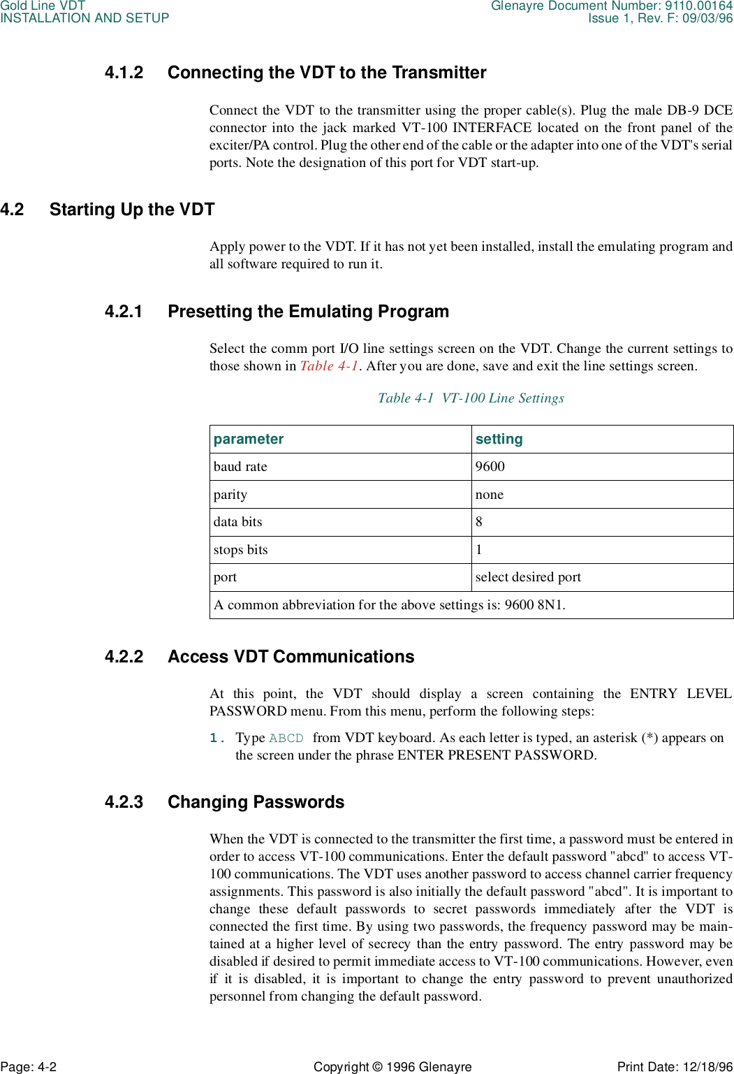
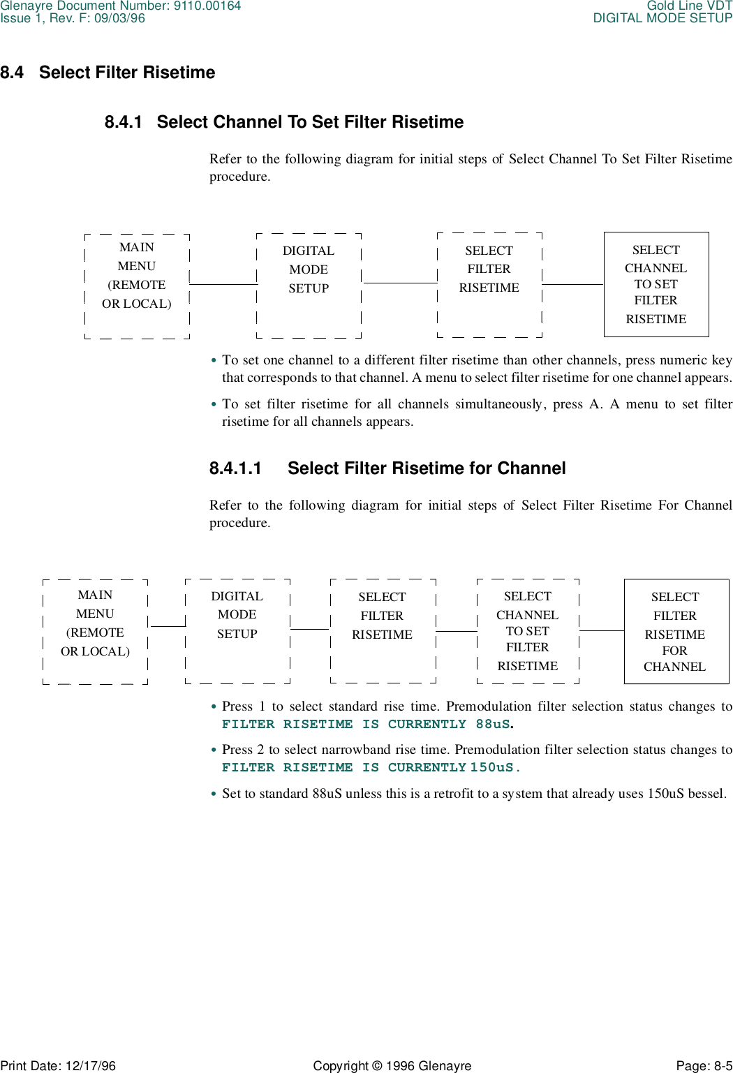
![Gold Line VDT Glenayre Document Number: 9110.00164OPERATION Issue 1, Rev. F: 09/03/96Page: 5-8 Copyright © 1996 Glenayre Print Date: 12/17/965.2.3 [Esc]The [ESC], or escape key, is active when all except top-level menus are displayed. Pressingthe escape key causes the previous menu to be displayed. The previous menu is the next-higher level, or one menu back. The escape key will not work if a Main Menu (remote orLocal) is displayed.5.2.4 Alphabetic Function KeysAlphabetic function keys are a group of letters that, when pressed, cause a predeterminedactivity to occur. Only some keys are active when a particular menu is displayed. An activealphabetic function key list is provided for each menu. The following is a list of all thealphabetic function keys:•M (display main menu)•R (refresh main menu)•K (key or unkey TX)•A (select all channels)•Y (yes, perform request)•N (no, do not perform request)•U (adjust value upwards)•D (adjust value downwards)M KeyPressing the M (main menu) key causes a main menu to be displayed, if it is not alreadydisplayed. If the transmitter is in remote control, the M key displays the Remote ControlMain Menu. If the transmitter is in local control, the M key displays the Local Control MainMenu.R KeyPressing the R (refresh) key causes a main menu to be displayed if it is not alreadydisplayed (the same as pressing the M key). The R key also causes the transmitter to updatethe status, currents, and powers values in the top half of the screen.K KeyPressing the K (key) key causes the transmitter to key, if unkeyed, or to unkey, if alreadykeyed. The K key is active in local control only. When local control is entered, the K keyis activated and the transmitter unkeys, if already keyed. When local control is exited, theK key is deactivated and the transmitter assumes the key state determined by the remotekey input.A KeyPressing the A (all) key causes the channel-all menu to be displayed for the parameterpresently selected. This key allows selection or change of a transmitter parameter for allchannels simultaneously, without having to select each channel individually.](https://usermanual.wiki/Glenayre-Electronics/GL-T8600-CN.Users-manual-part-4/User-Guide-12766-Page-28.png)

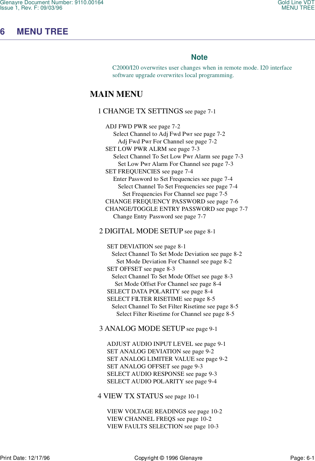
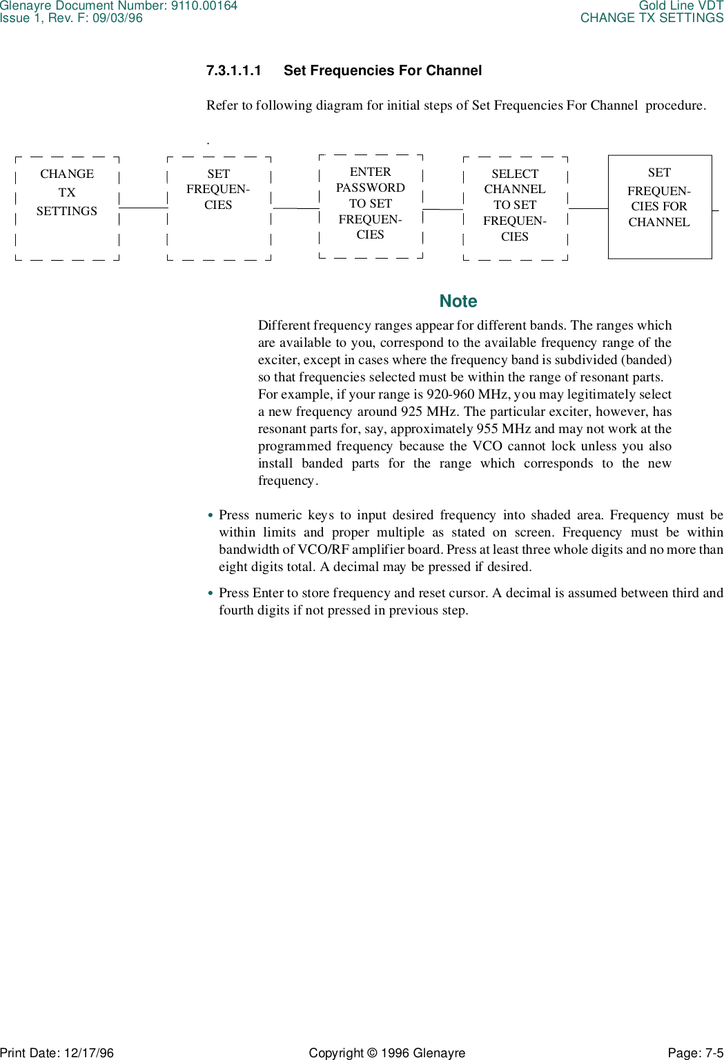
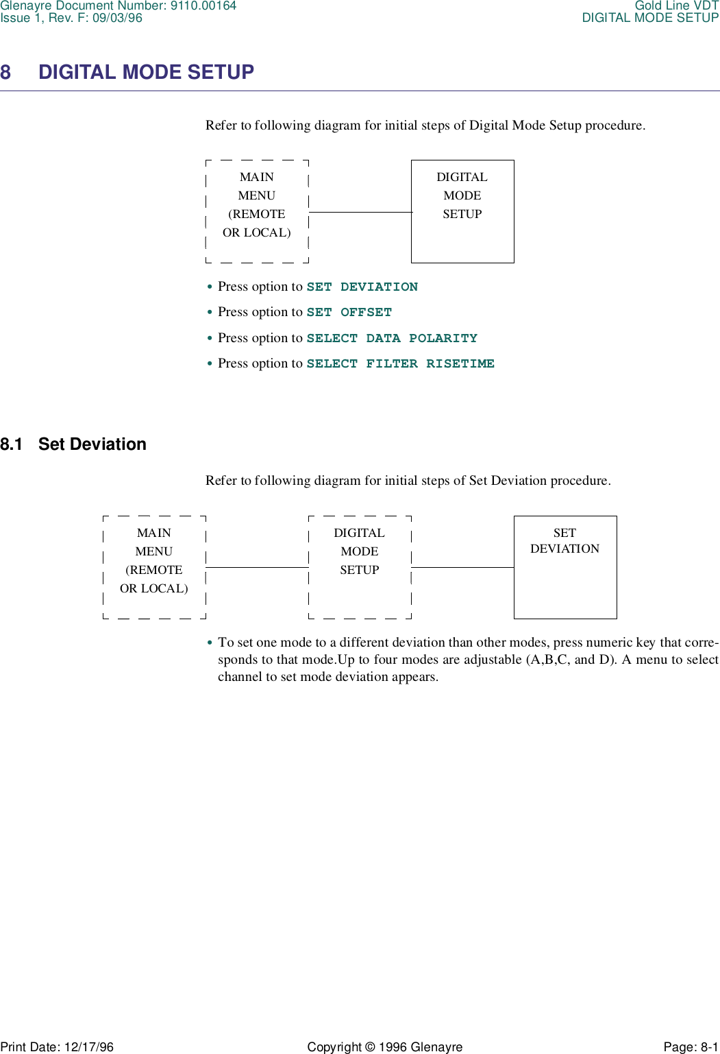
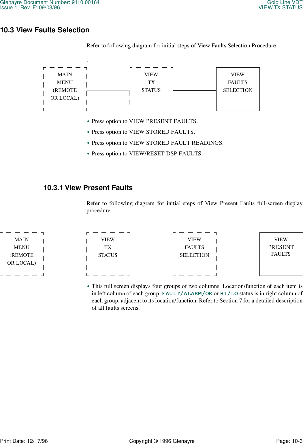
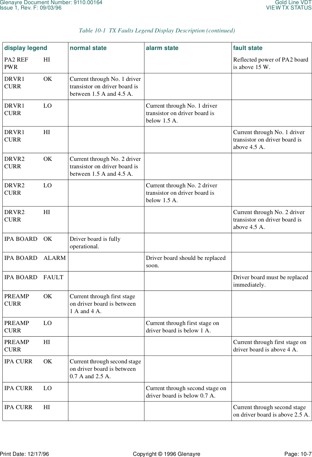
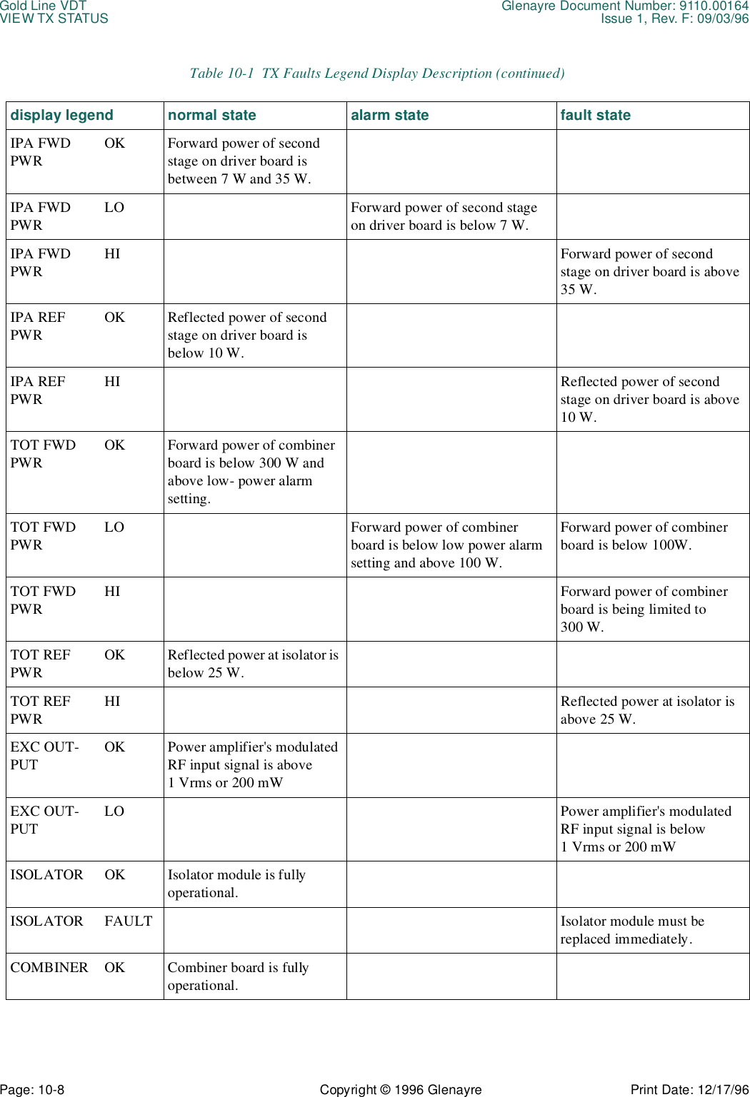
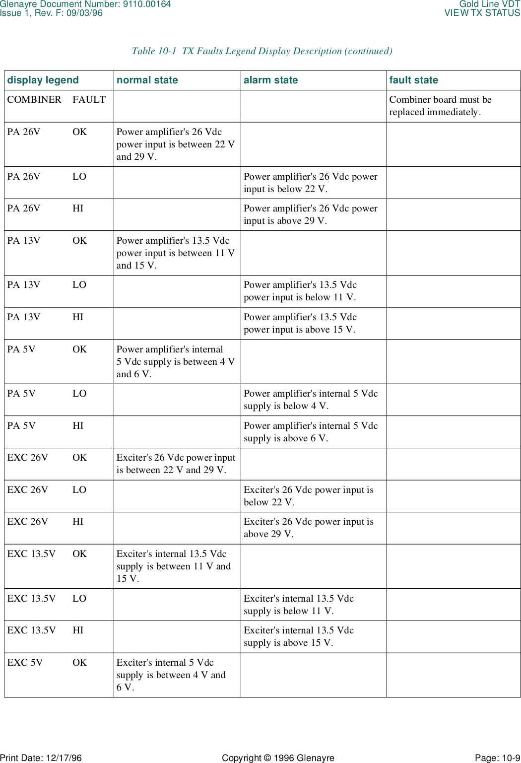
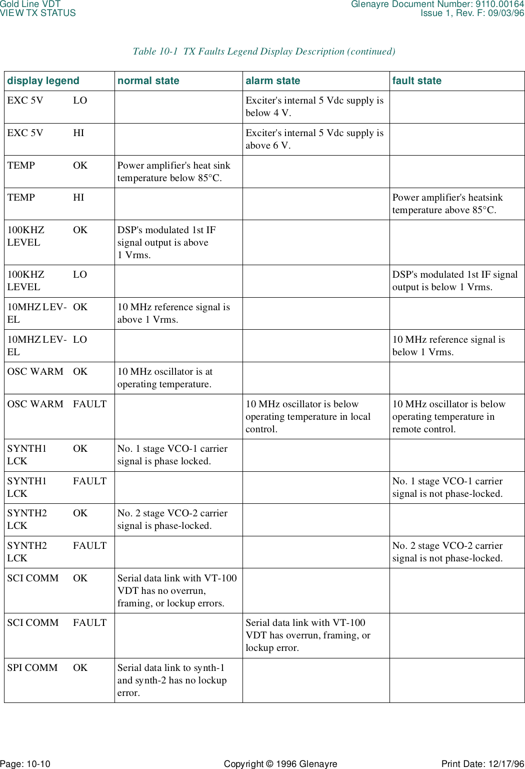
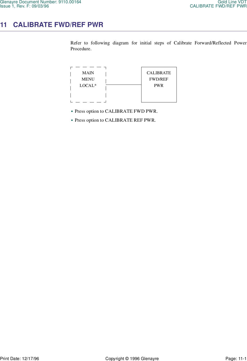
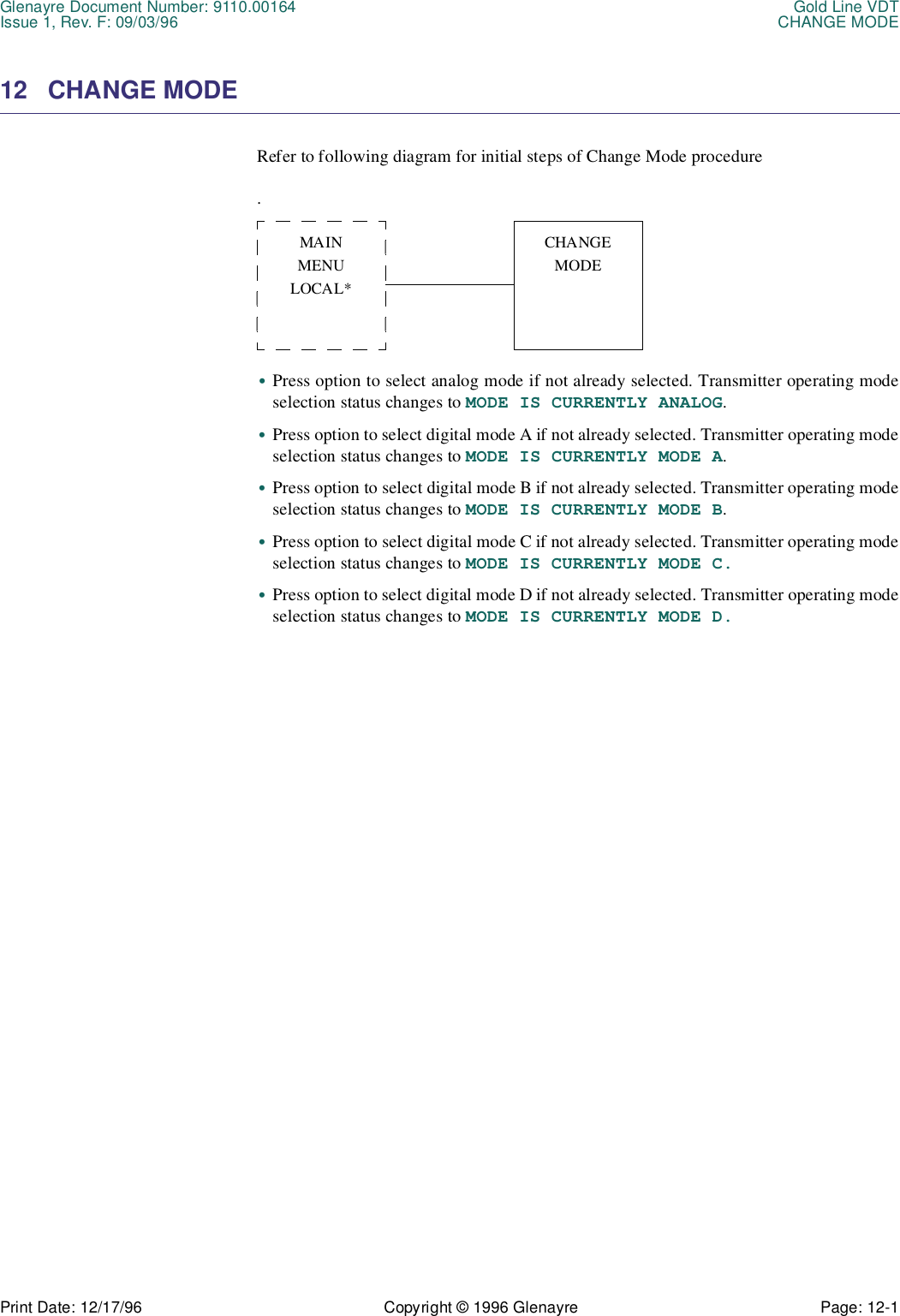
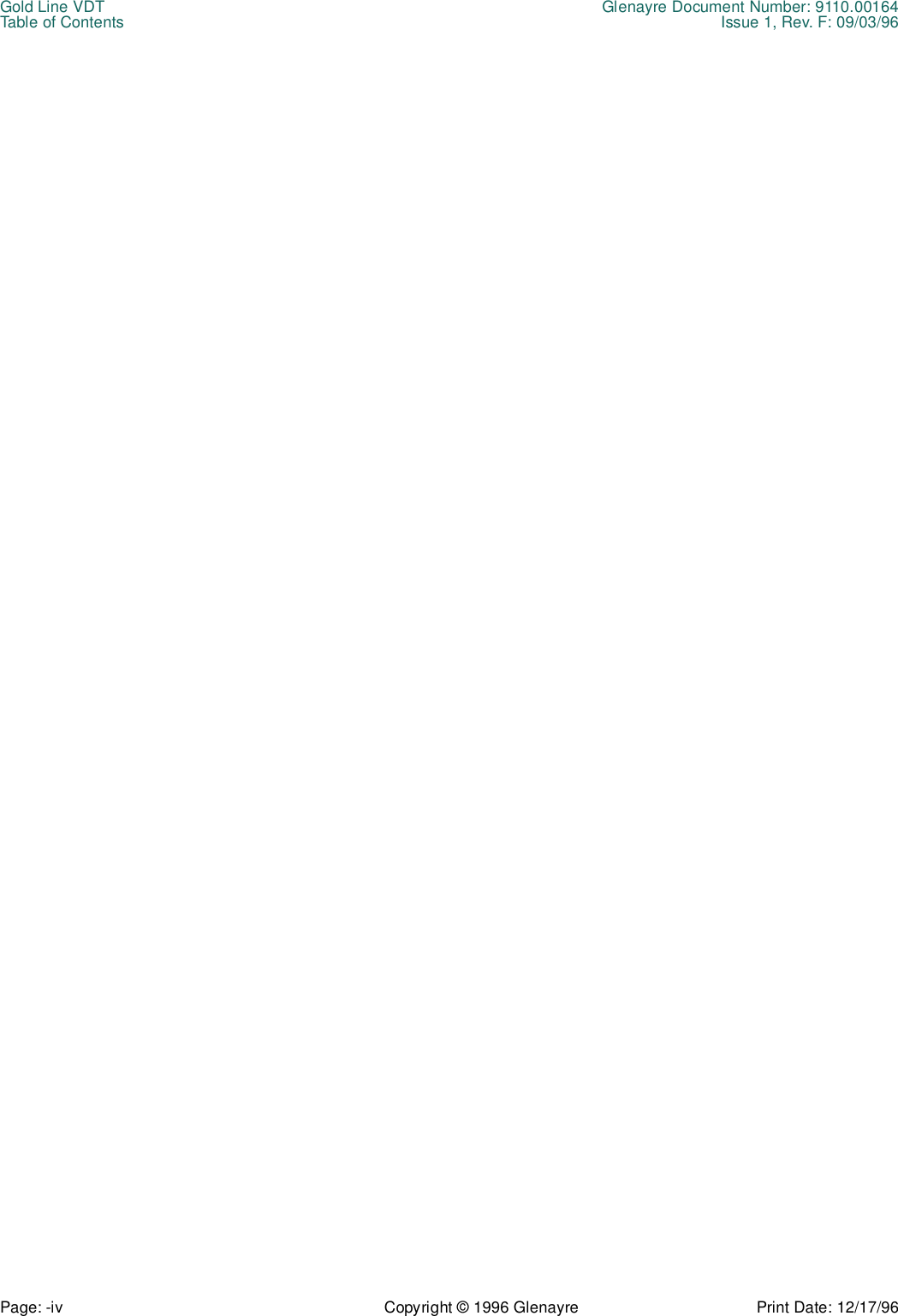
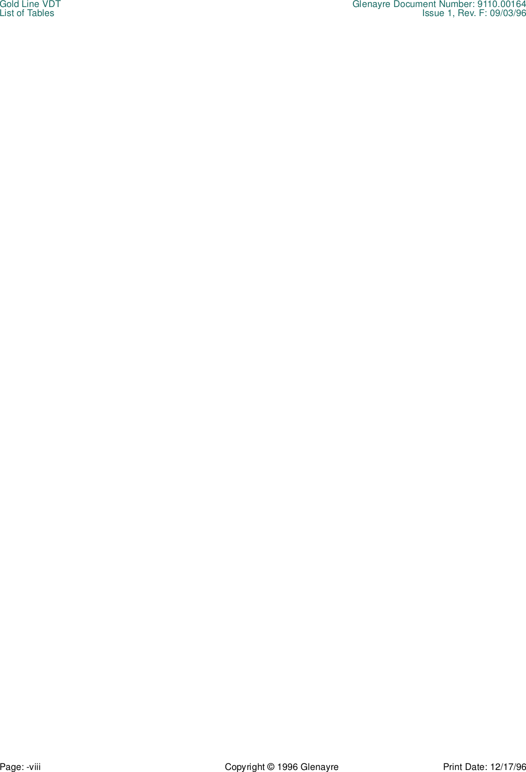
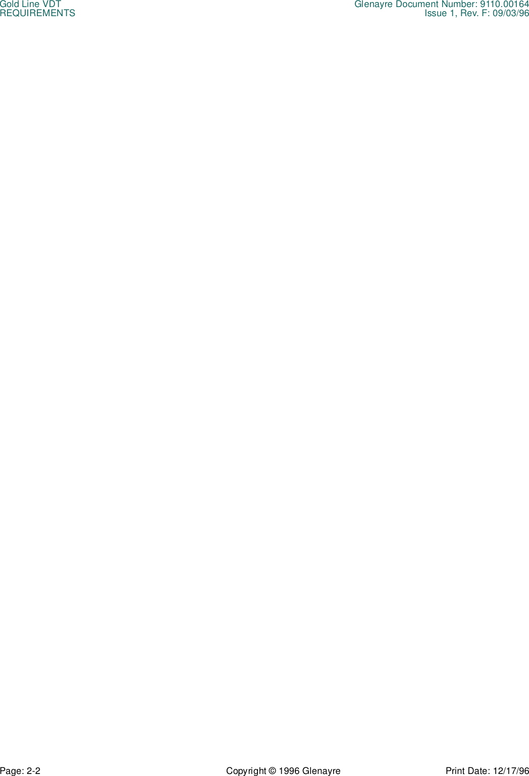
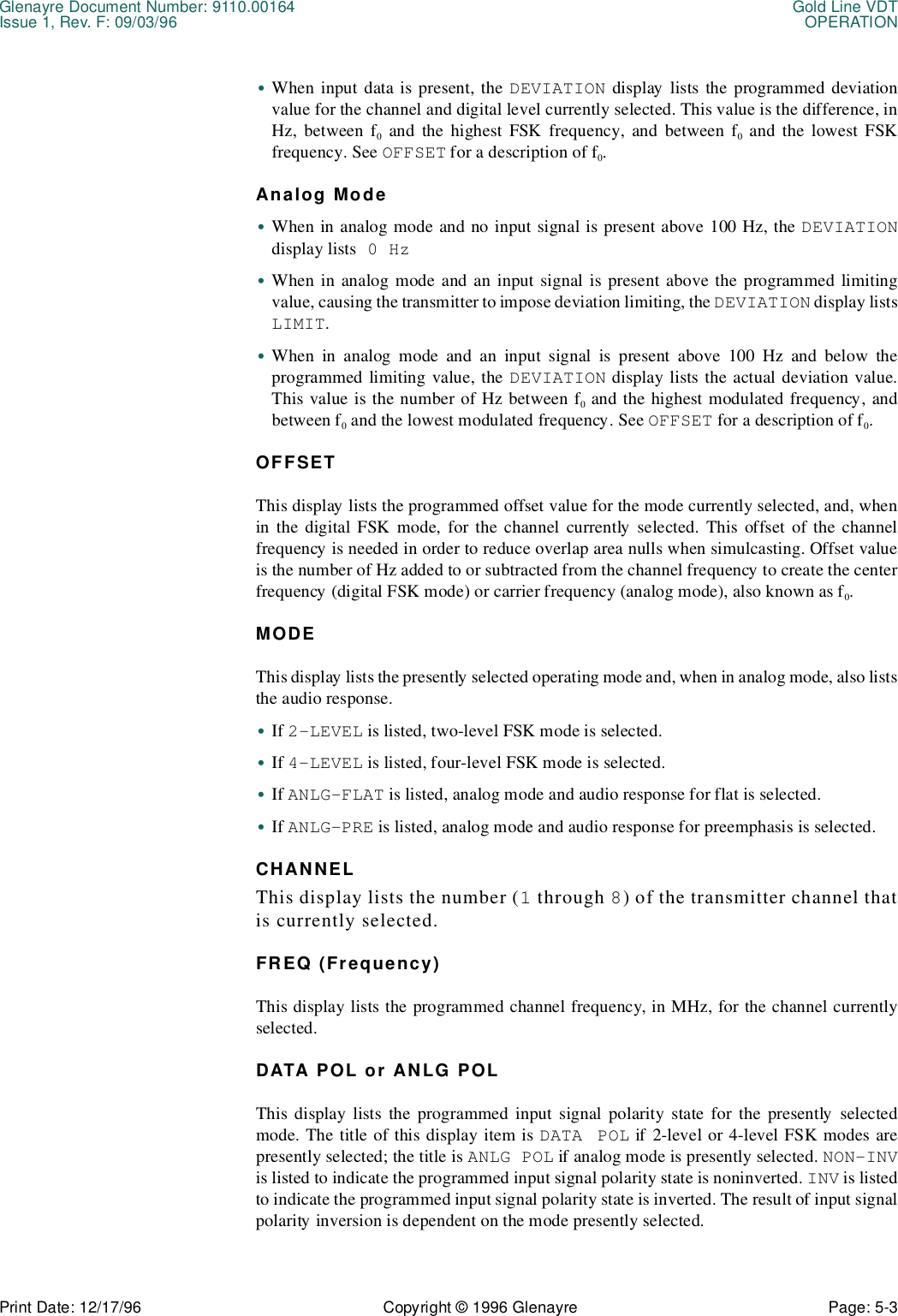
![Glenayre Document Number: 9110.00164 Gold Line VDTIssue 1, Rev. F: 09/03/96 VIEW TX STATUSPrint Date: 12/17/96 Copyright © 1996 Glenayre Page: 10-5 Table 10-1 TX Faults Legend Display Descriptiondisplay legend normal state alarm state fault statePA1 BOARD OK PA1 board is fully operational.PA1 BOARD ALARM PA1 board should be replaced soon.PA1 BOARD FAULT PA1 board must be replaced immediately.PA1-A CURROK Current through A pair of transistors on PA1 board is within window:(PA1 FWD ÷ PA SUPPLY VOLTAGE) ±2.5A.PA1-A CURRLO Current through A pair of transistors on PA1 board is below window or below 2.0A.PA1-A CURRHI Current through A pair of transistors on PA1 board is above window and below 9A.Current through A pair of transistors on PA1 board is above 9A.PA1-B CURR OK Current through B pair of transistors on PA1 board is within window:(PA1 FWD ÷ PA SUPPLY VOLTAGE) ±2.5A.PA1-B CURR LO Current through B pair of transistors on PA1 board is below window or below 2.0A.PA1-B CURR HI Current through B pair of transistors on PA1 board is above window and below 9A.Current through B pair of transistors on PA1 board is above 9A.PA1 FWD PWROK Forward power of PA1 board is within window:[(FWD PWR + 25%) ÷ NO. of PA BOARDS]+ 33%/-50%.PA1 FWD PWRLO Forward power of PA1 board is below window.PA1 FWD PWR HI Forward power of PA1 board is above window. PA1 REF PWR OK Reflected power of PA1 board is below 15 W](https://usermanual.wiki/Glenayre-Electronics/GL-T8600-CN.Users-manual-part-4/User-Guide-12766-Page-57.png)
![Gold Line VDT Glenayre Document Number: 9110.00164VIEW TX STATUS Issue 1, Rev. F: 09/03/96Page: 10-6 Copyright © 1996 Glenayre Print Date: 12/17/96PA1 REF PWR HI Reflected power of PA1 is above 15 W.PA2 BOARD OK PA2 board is fully operational.PA2 BOARD ALARM PA2 board should be replaced soon.PA2 BOARD FAULT PA2 board must be replaced immediately.PA2-A CURROK Current through A pair of transistors on PA2 board is within window:(PA2 fwd ÷ PA supply voltage) ±2.5 A.PA2-A CURRLO Current through A pair of transistors on PA2 board is below window or below 2.0 A.PA2-A CURRHI Current through A pair of transistors on PA2 board is above window and below 9 A.Current through A pair oftransistors on PA2 board is above 9 A.PA2-B CURR OK Current through B pair of transistors on PA2 board is within window:(PA2 FWD ÷ PA SUPPLY VOLTAGE) ±2.5 A.PA2-B CURR LO Current through B pair of transistors on PA2 board is below window or below 2.0A.PA2-B CURR HI Current through B pair of transistors on PA2 board is above window and below 9 A.Current through B pair of transistors on PA2 board is above 9 A.PA2 FWD PWROK Forward power of PA2 board is within window:[(FWD PWR + 25%) ÷ NO. OF PA BOARDS]+ 33%/-50%.PA2 FWD PWRLO Forward power of PA2 board is below window.PA2 FWD PWRHI Forward power of PA2 board is above window.PA2 REF PWROK Reflected power of PA2 board is below 15 W.Table 10-1 TX Faults Legend Display Description (continued)display legend normal state alarm state fault state](https://usermanual.wiki/Glenayre-Electronics/GL-T8600-CN.Users-manual-part-4/User-Guide-12766-Page-58.png)