Glenayre Electronics GL-T8200 Low Power Transmitter for 1 and 2way wireless data User Manual
Glenayre Electronics Inc Low Power Transmitter for 1 and 2way wireless data
Contents
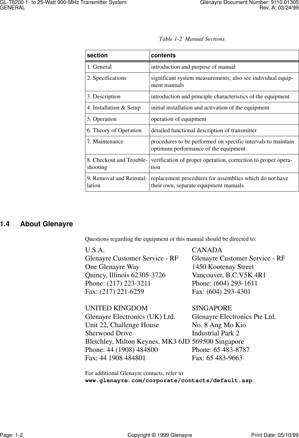
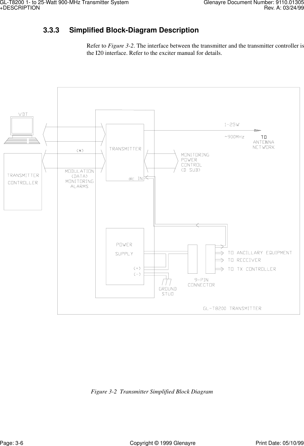
- 1. Composite of users manuals
- 2. Exciter manual
Composite of users manuals