GemTek Technology AP931229AG Dual Radio 2.4GHz/5GHz Outdoor Access Point User Manual BW2250 MRD
Gemtek Technology Co., Ltd. Dual Radio 2.4GHz/5GHz Outdoor Access Point BW2250 MRD
UserManual.wiki
>
GemTek Technology
>
AP931229AG User Manual
>
Manual
Contents
1.
Users Manual
2.
Manual
Manual
Navigation menu
Upload a User Manual
Namespaces
Wiki Guide
HTML
PDF
Info
Views
User Manual
Discussion / Help
Navigation
![BROWAN COMMUNICATIONS Page 6 Purpose The purpose of this document is to collect, analyze, and define needs and features of the new BROWAN BW2250 Dual Radio 2.4GHz/5GHz Outdoor Access Point. Prerequisite Skills and Knowledge To use this document effectively, you should have a working knowledge of Local Area Networking (LAN) concepts and wireless Internet access infrastructures. In addition, you should be familiar with the following: Hardware installers should have a working knowledge of basic electronics and mechanical assembly, and should understand related local building codes. Network administrators should have a solid understanding of software installation procedures for network operating systems under Microsoft Windows 95, 98, Millennium, 2000, NT, and Windows XP and general networking operations and troubleshooting knowledge. Conventions Used in this Document The following typographic conventions and symbols are used throughout this document: Very important information. Failure to observe this may result in damage. Important information that should be observed. Additional information that may be helpful but which is not required. bold Menu commands, buttons and input fields are displayed in bold code File names, directory names, form names, and system-generated output such as error messages are displayed in constant-width type <value> Placeholder for certain values, e.g. user inputs [value] Input field format, limitations, and/or restrictions. Help Us to Improve this Document! If you should encounter mistakes in this document or want to provide comments to improve the manual please send e-mail directly to: manuals@browan.com Browan Technical Support If you encounter problems when installing or using this product, please consult the Browan website at www.browan.com for: Direct contact to the Browan support centers. Frequently Asked Questions (FAQ). Download area for the latest software, user documentation and product updates. About this Guide](https://usermanual.wiki/GemTek-Technology/AP931229AG.Manual/User-Guide-714868-Page-7.png)
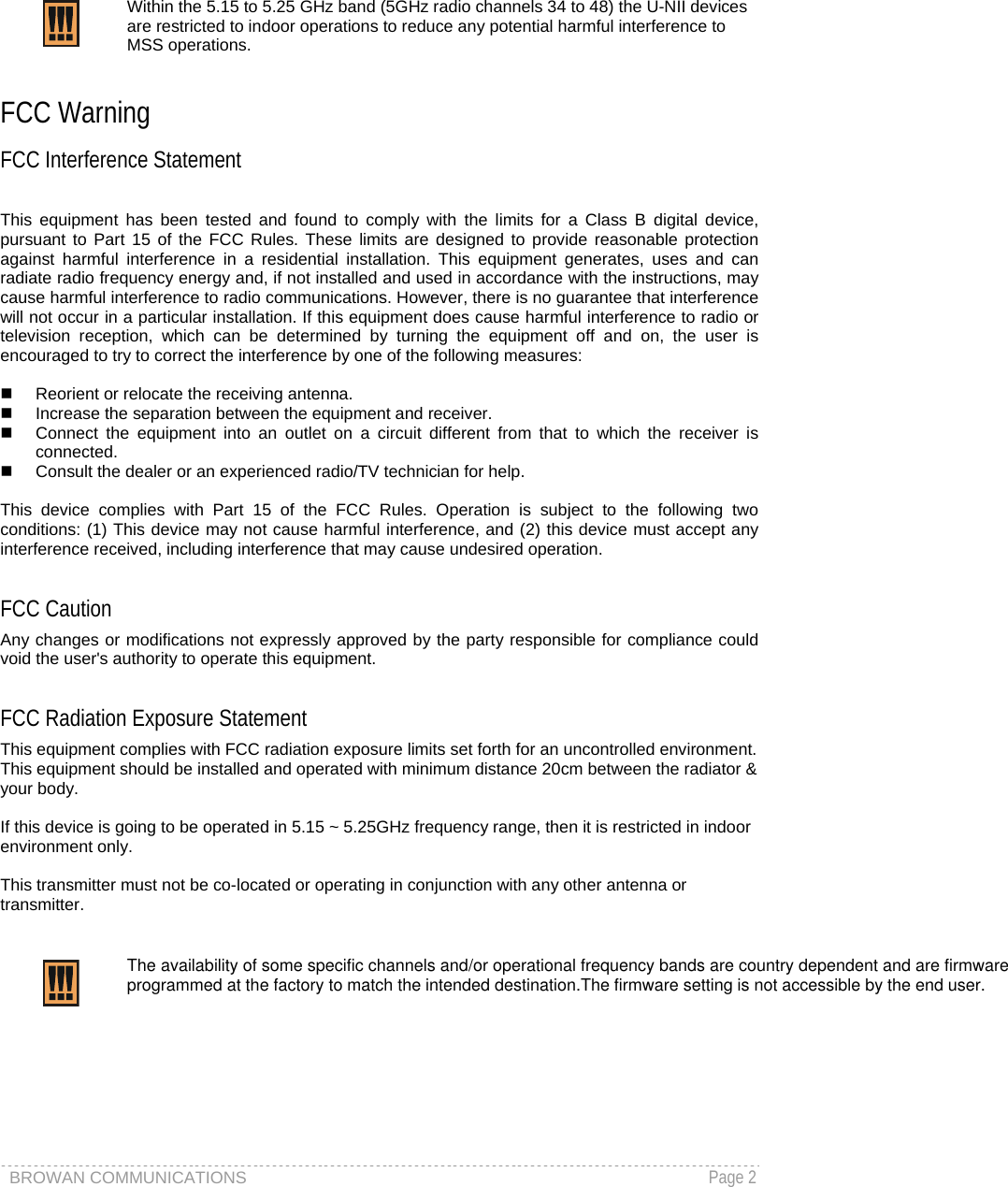
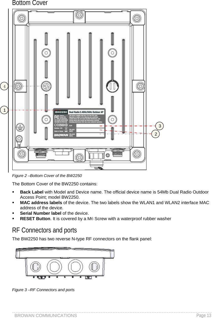
![BROWAN COMMUNICATIONS Page 12 Hardware Introduction General Overview Figure 1 – BW2250 General View The front panel of BW2250 contains: Connectors which enable you to make different network connections for the device Waterproof ports, which prevent the device from the damage of water that get into the internal part of the device. The Bottom cover of BW2250 contains: Thermal convection hole Reset button enables you to reboot or reset the device configuration to the factory defaults Press the Reset button for less than 3 seconds to reboot the device. Press the Reset button for more than 10 seconds to set the device to factory defaults. 註解 [r1]: 增加作用说明](https://usermanual.wiki/GemTek-Technology/AP931229AG.Manual/User-Guide-714868-Page-13.png)
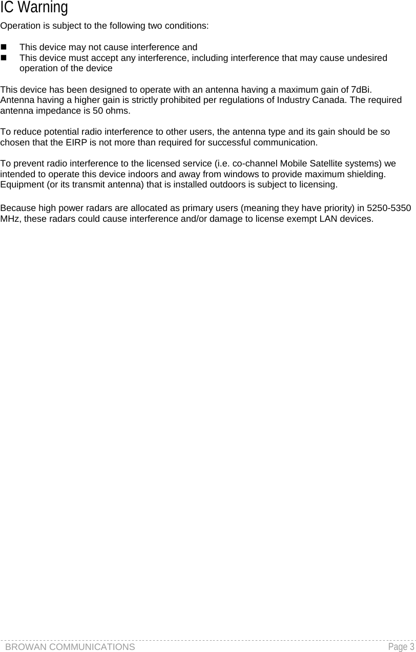
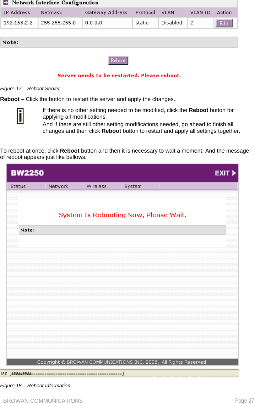
![BROWAN COMMUNICATIONS Page 26 To change network interface (bridge) configuration properties click the Edit button in the Action column. The status can be changed now: Figure 15 – Edit Interface Configuration Settings IP Address - specify new interface IP address [in digits and dots notation, e.g. 192.168.123.70]. Netmask – specify the subnet mask [[0-255].[0-255].[0-255].[0-255]]. These numbers is a binary mask of the IP address, which defines IP address order and the number of IP addresses in the subnet. Gateway Address – interface gateway. For Bridge type interfaces, the gateway is always the gateway router. Protocol – specify static for setting IP address manually and dhcp for getting IP address dynamically acting as DHCP client. When dhcp is used for getting IP address, Kickstart is strongly recommended to find your device. VLAN –specify whether to manage this device via VLAN. VLAN ID – specify VLAN ID when managing this device via VLAN. Save – save the entered values. Cancel – restore all previous values. Change status or leave in the default state if no editing is necessary and click the Save button. Figure 16 – Apply or Discard Interface Configuration Changes Apply Changes – to save all changes in the interface table at once. Discard Changes – restore all previous values. For such each change of settings, the BW2250 needs to be restarted to apply all settings changes when clicking Apply Changes. Request for reboot server appears:](https://usermanual.wiki/GemTek-Technology/AP931229AG.Manual/User-Guide-714868-Page-27.png)
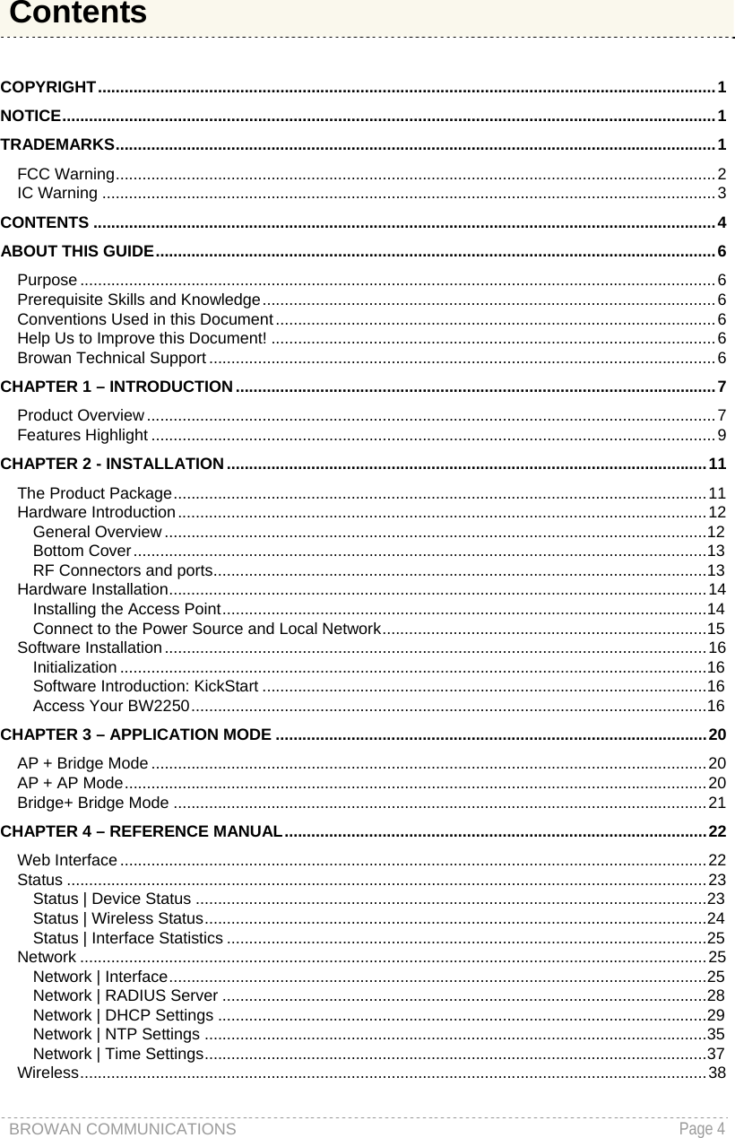
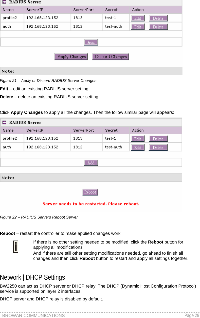
![BROWAN COMMUNICATIONS Page 28 Network | RADIUS Server Up to 32 different RADIUS servers can be configured under the RADIUS servers menu. By default, one RADIUS server is specified for the system: Figure 19 – RADIUS Servers Settings Add – add new RADIUS server. Click Add to configure RADIUS server settings. Figure 20 – RADIUS Server's Details Name – specify the new RADIUS server name, which is used for selecting RADIUS server. Server IP – authentication RADIUS server IP address [dots and digits]. Server Port – specify the network port used to communicate with RADIUS [1-65535]. The default port value for authentication is 1812. The default port value for accounting is 1813. The port specified here must be the same with the one on the RADIUS server. Secret – shared secret string that is used to make sure the integrity of data frames used for authentication server. Save – save new specified RADIUS server. Cancel – restore all previous values. After adding a new RADIUS server, the following control appears:](https://usermanual.wiki/GemTek-Technology/AP931229AG.Manual/User-Guide-714868-Page-29.png)
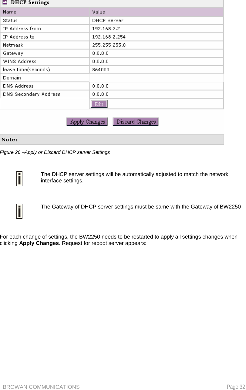
![BROWAN COMMUNICATIONS Page 31 Figure 25 –DHCP server Settings By default, DHCP server is disabled for BW2250. IP Address from / IP Address to – specify the IP address range to be dynamically allocated by the DHCP server. Netmask – enter the netmask for IP pool range. Gateway – enter the gateway IP for wireless clients. WINS Address (Windows Internet Naming Service) – specify server IP address if it is available on the network [dots and digits]. Lease Time – specify the IP address lease interval in seconds [1-1000000]. Domain – specify the DHCP domain name [optional, 1-128 sting]. DNS address – specify the DNS server’s IP address [in digits and dots notation]. DNS secondary address – specify the secondary DNS server’s IP address [in digits and dots notation]. Change status or leave in the default state if no editing is necessary and click the Save button.](https://usermanual.wiki/GemTek-Technology/AP931229AG.Manual/User-Guide-714868-Page-32.png)
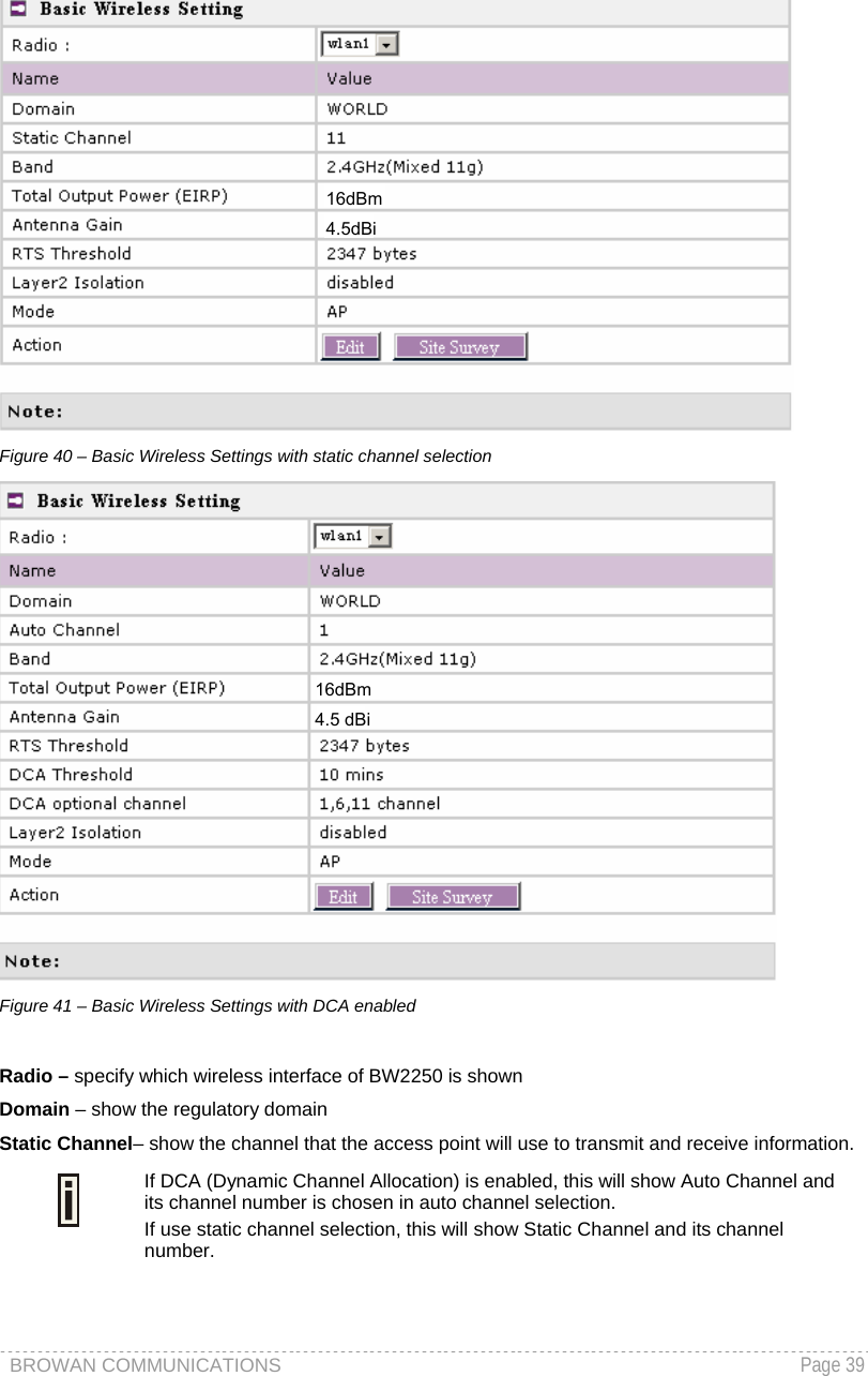
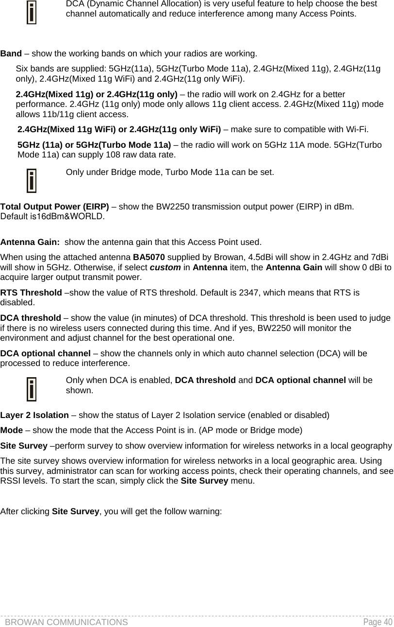

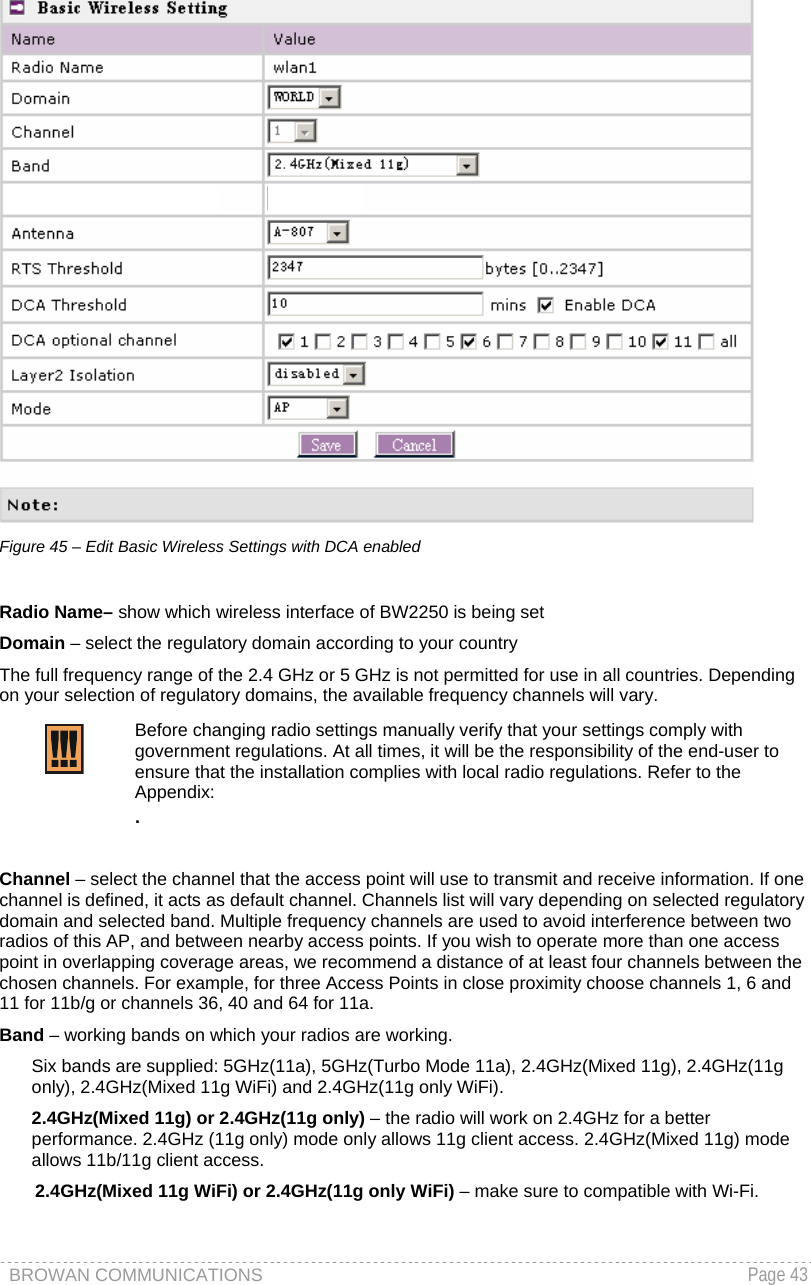
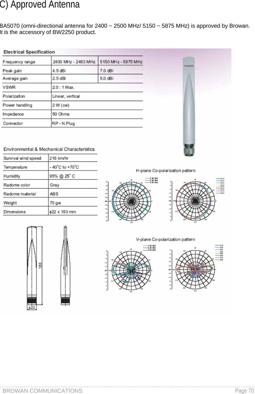
![BROWAN COMMUNICATIONS Page 44 5GHz (11a) or 5GHz(Turbo Mode 11a) – the radio will work on 5GHz 11A mode. 5GHz(Turbo Mode 11a) can supply 108 raw data rate. Only under Bridge mode, Turbo Mode 11a can be set. Total Output Power (EIRP) –the BW2250 transmission output power (EIRP) in dBm. Default is 16dBm&WORLD. Total Output Power (EIRP) = Antenna Gain + RF card output power Antenna: Type of Antenna, two items for choice. BA5070 is the approved antenna supplied by Browan. Choose BA5070 antenna is used for meeting the limitation of regulatory domain. If you want to gain a larger output power for the real usage, it is strongest recommended to select custom. BA5070 antenna is the accessory of BW2250 Product. Refer to the Appendix D for BA5070 Antenna Spec: D) Approved Antenna If you want to gain a larger output power for the real usage, it is strongly recommended to select custom. RTS Threshold – when set, this setting specifies the maximum packet size beyond which RTS/CTS mechanism is be invokes. The value range of this is [0 …2347]. Default is 2347, which means that RTS is disabled. Enable DCA – Enable or Disable DCA service. DCA can help to choose the best working channel automatically. And static channel selection will be forbidden if DCA is enabled. DCA (Dynamic Channel Allocation) solution automatically selects the optimal operational frequency channel when power up and periodically monitors the environment and adjusts for the best operational frequency channel. DCA service is available only under 2.4GHz band. DCA threshold – specify the value (in minutes) of DCA threshold. This threshold is been used to judge if there is no wireless users connected during this time. And if yes, BW2250 will monitor the environment and adjust channel for the best operational one. If wireless network environment is stable which means auto channel selection needn’t do frequently, set a big value for DCA threshold to gain a stable wireless users’ connection. If wireless network environment changes continually, frequent auto channel selection is needed. So set a relative small value for DCA threshold to let channel change based on wireless environment. Wireless users’ will be kicked off when DCA is processing (site survey and new operational frequency channel takes effect).](https://usermanual.wiki/GemTek-Technology/AP931229AG.Manual/User-Guide-714868-Page-45.png)
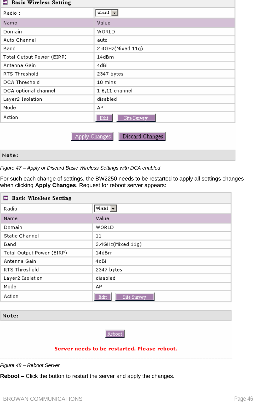
![BROWAN COMMUNICATIONS Page 45 DCA optional channel – specify the channels only in which auto channel selection (DCA) will choose for reducing interference reference. Only when DCA is enabled, DCA threshold and DCA optional channel will be shown. Layer 2 Isolation – Layer2 wireless client separation. Connected clients with user isolation function enabled cannot access each other directly. The clients are isolated from each other using their MAC addresses [enabled/disabled]. Mode – two modes are supplied: AP mode and Bridge mode. When Bridge mode is enabled, BW2250 can introduce a bridge loop if BW2250 Ethernet port is connected to your wired LAN. To avoid a bridge loop on your network, disconnect BW2250 from the wired LAN before or soon after Bridge mode is enabled. Save – Save the settings Change status or leave in the default state if no editing is necessary and click the Save button. Figure 46 – Apply or Discard Basic Wireless Settings with static channel selection 16dBm4.5 dBi](https://usermanual.wiki/GemTek-Technology/AP931229AG.Manual/User-Guide-714868-Page-46.png)
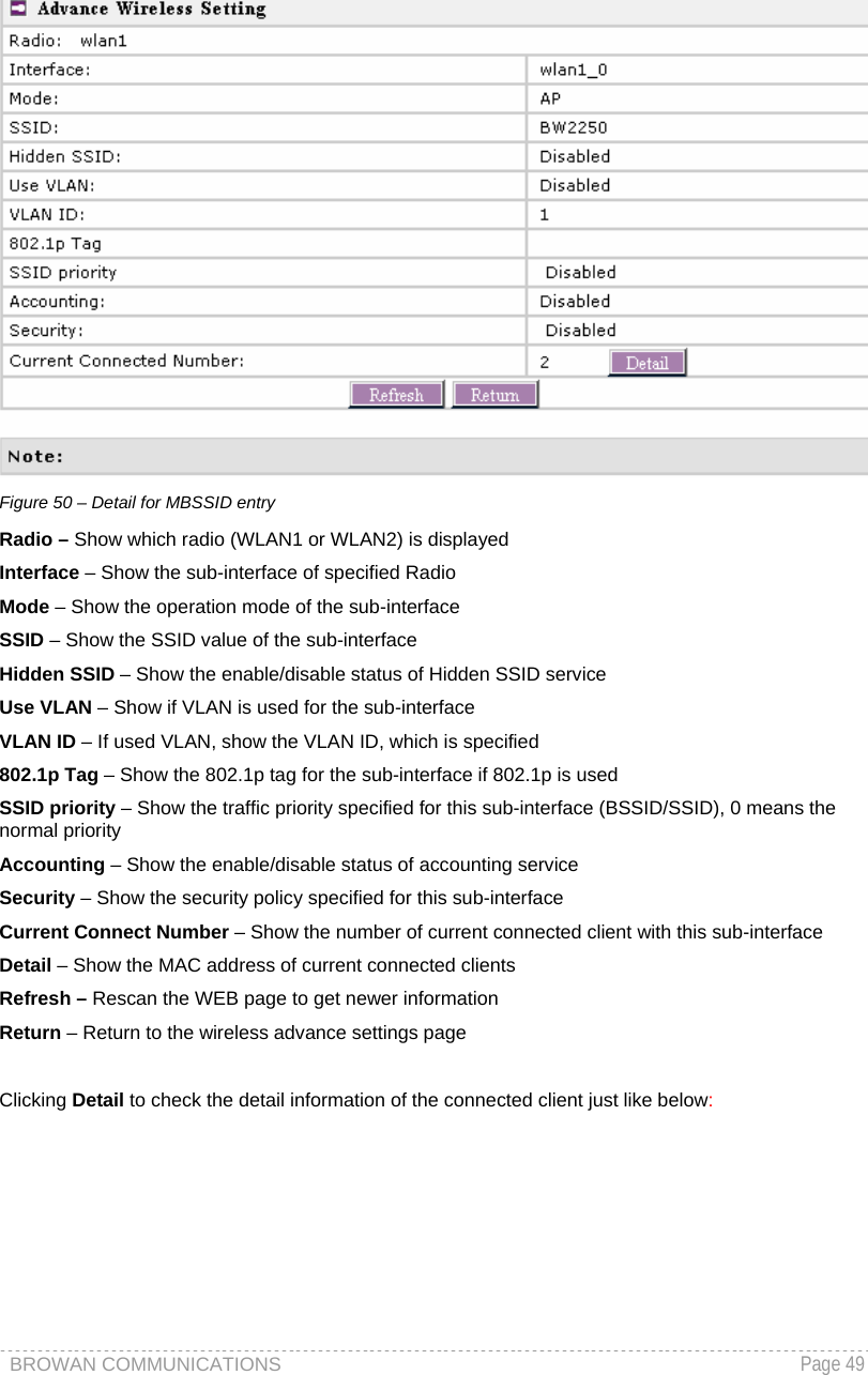
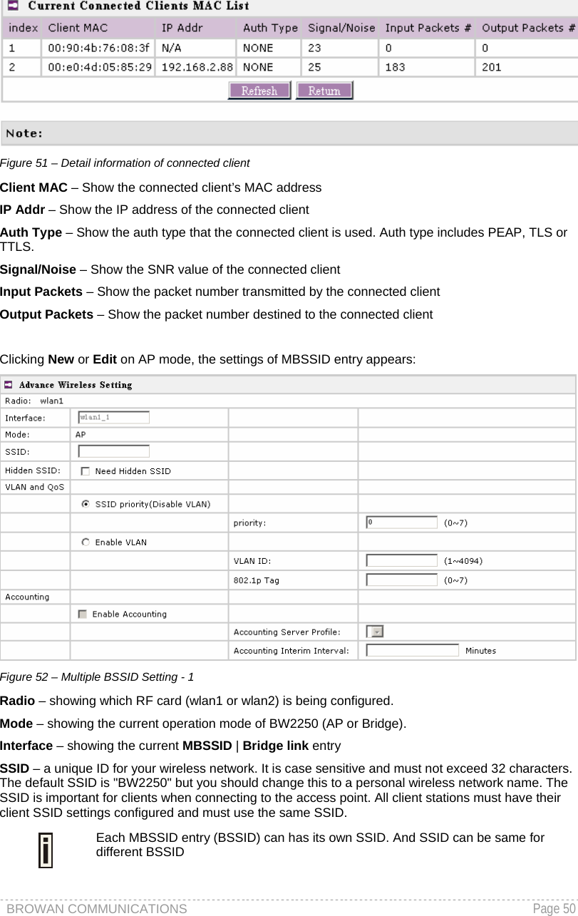
![BROWAN COMMUNICATIONS Page 51 Hidden SSID – When enabled, the SSID of this Interface is invisible in the networks list while scanning the available networks for wireless client (SSID is not broadcasted with its Beacons). When disabled, the AP’s SSID is visible in the available network list [enabled/disabled]. By default the Hidden SSID is disabled. VLAN and QoS – Specify VLAN policy or QoS policy. Data priority is based on (B) SSID and implemented by 802.11e EDCA or 802.1p tag. SSID priority (Disable VLAN) – specify the data priority, which is implemented according to 802.11e EDCA and makes sure the wireless downlink over-air QoS. This priority is based on (B) SSID, which means different BSSID can have different data priority and the data of the same BSSID has the same priority. This data priority only makes sure the priority of downlink (from AP to wireless client). 8 levels priorities are supplied. 1, 2, 0, 3, 4, 5, 6, 7 is from lowest priority to highest priority. And if no special QoS is needed, leave priority to default (0). 0 means normal priority. Enable VLAN – When enabled, the outgoing packets from this SSID will be tagged with VLAN ID and 802.1p tag (If have). VLAN ID – Configure VLAN ID for each Multiple SSID devices. Valid numbers are from 1 to 4094. 802.1p Tag – Configure 802.1p Tag for remote APC’s or Router’s QoS uses. Valid numbers are from 0 to 7. VLAN ID and 802.1p tag must cooperate with remote Router or APC. 802.1p Tag is also used for data priority. 8 levels priorities are supplied. 1, 2, 0, 3, 4, 5, 6, 7 is from lowest priority to highest priority. Accounting – Control the status of accounting service. Enable Accounting – enable or disable the accounting service. Accounting service only can be enabled when the security policy using RADIUS server is chosen. The security policies using RADIUS server include 802.1x, WPA, WPA2, WPA2 MIXED and MAC auth. Accounting Server Profile – specify which RADIUS server is used for accounting service. If not have any RADIUS server: please configure Network | RADIUS Servers Web UI first. Accounting Interim Interval – specify the value (in minutes), which is used for interim-accounting interval. This should not be left empty and the value range is from 1 to 60 minutes.](https://usermanual.wiki/GemTek-Technology/AP931229AG.Manual/User-Guide-714868-Page-52.png)
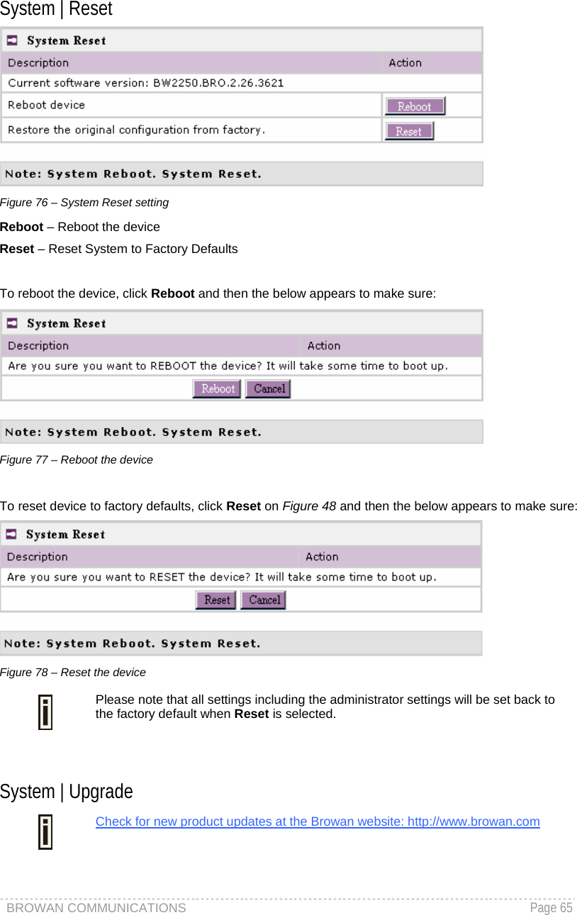
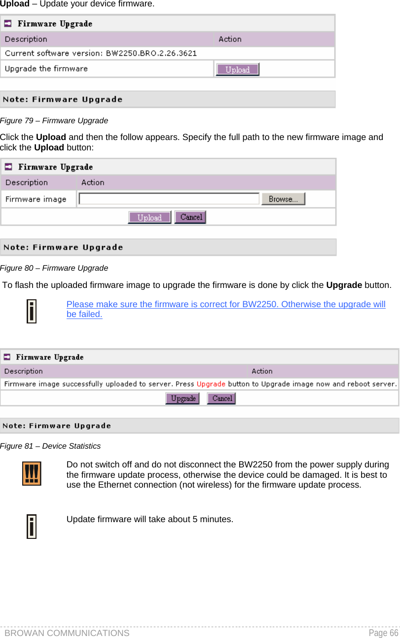
![BROWAN COMMUNICATIONS Page 60 System System | Security Use the System | Security service to configure the name and password administrator: Figure 65 – system security settings User Name – administrator username for access to BW2250 (e.g. web interface, CLI mode) [1-32 symbols, spaces not allowed]. Old Password – old password value. New Password –new password value used for user authentication in the system [4-8 characters, spaces not allowed]. Confirm Password – re-enter the new password to verify its accuracy. Save – click to save new administrator settings. Default administrator logon settings are: User Name: admin Password: admin01 Password length is from 4 to 8 characters. After filling in the right old password and the new password, clicking the Save button for taking effect immediately. After clicking Save button, the below UI will be shown to notify that the new password setting has been taken place:](https://usermanual.wiki/GemTek-Technology/AP931229AG.Manual/User-Guide-714868-Page-61.png)
![BROWAN COMMUNICATIONS Page 61 Figure 66 – system security settings save and take effect successfully System | SNMP SNMP is the standard protocol that regulates network management over the Internet. To communicate with SNMP manager you must set up the same SNMP communities and identifiers on both ends: manager and agent. Use the System | SNMP menu to change current SNMP configuration. Figure 67 – SNMP settings Readonly community – Community name is used in SNMP version 1 and version 2c. Read-only (public) community allows reading values, but denies any attempt to change values [1-32 all ASCII printable characters, no spaces]. Readwrite community – Community name is used in SNMP version 1 and version 2c. Read-write (private) community allows to read and (where possible) change values [1-32 all ASCII printable characters, no spaces]. Default Trap community – The default SNMP community name used for traps without specified communities. The default community by most systems is "public". The community string must match the community string used by the SNMP network management system (NMS) [1-32 all ASCII printable characters, no spaces]. Trap Configuration Table:](https://usermanual.wiki/GemTek-Technology/AP931229AG.Manual/User-Guide-714868-Page-62.png)
![BROWAN COMMUNICATIONS Page 62 You can configure your SNMP agent to send SNMP Traps (and/or inform notifications) under the defined host (SNMP manager) and community name (optional). Figure 68 – SNMP Trap table settings Click Add to add a new SNMP manager or Delete to delete a specific SNMP manager. Clicking Add: Figure 69 – Add SNMP Trap Host IP – enter SNMP manager IP address [dots and digits]. Host Port – enter the port number the trap messages should be send through [number]. Trap Type – select trap message type [v1/v2/inform]. Community – specify the community name at a SNMP trap message. This community will be used in trap messages to authenticate the SNMP manager. If not defined, the default trap community name will be used (specified in the SNMP table) [1-32 all ASCII printable characters, no spaces]. Save – save all current settings Cancel – restore the last settings System | Telnet Use System | Telnet menu to manage the telnet/SSH service of your BW2250. Figure 70 – System Configuration settings Telnet Service – Enable or disable telnet service of BW2250 SSH Service – Enable or disable SSH service of BW2250. The default of these two services are all Enabled. The current IETF SSH (SSHv2) is supported for security of accessing BW2250 via telnet/CLISH.](https://usermanual.wiki/GemTek-Technology/AP931229AG.Manual/User-Guide-714868-Page-63.png)
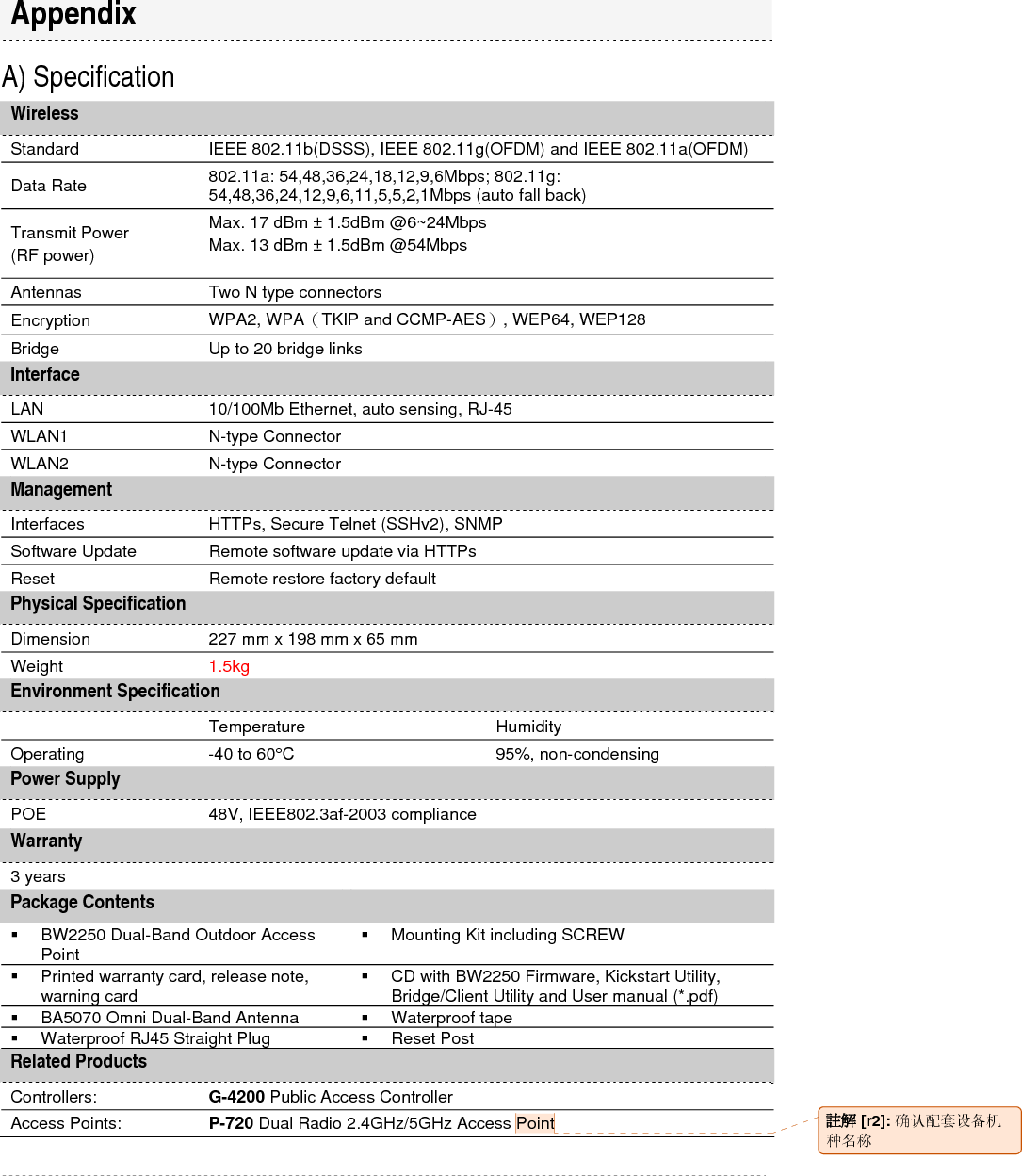
![BROWAN COMMUNICATIONS Page 67 A) Specification Wireless Standard IEEE 802.11b(DSSS), IEEE 802.11g(OFDM) and IEEE 802.11a(OFDM) Data Rate 802.11a: 54,48,36,24,18,12,9,6Mbps; 802.11g: 54,48,36,24,12,9,6,11,5,5,2,1Mbps (auto fall back) Transmit Power (RF power) Max. 17 dBm ± 1.5dBm @6~24Mbps Max. 13 dBm ± 1.5dBm @54Mbps Antennas Two N type connectors Encryption WPA2, WPA(TKIP and CCMP-AES), WEP64, WEP128 Bridge Up to 20 bridge links Interface LAN 10/100Mb Ethernet, auto sensing, RJ-45 WLAN1 N-type Connector WLAN2 N-type Connector Management Interfaces HTTPs, Secure Telnet (SSHv2), SNMP Software Update Remote software update via HTTPs Reset Remote restore factory default Physical Specification Dimension 227 mm x 198 mm x 65 mm Weight 1.5kg Environment Specification Temperature Humidity Operating -40 to 60°C 95%, non-condensing Power Supply POE 48V, IEEE802.3af-2003 compliance Warranty 3 years Package Contents BW2250 Dual-Band Outdoor Access Point Mounting Kit including SCREW Printed warranty card, release note, warning card CD with BW2250 Firmware, Kickstart Utility, Bridge/Client Utility and User manual (*.pdf) BA5070 Omni Dual-Band Antenna Waterproof tape Waterproof RJ45 Straight Plug Reset Post Related Products Controllers: G-4200 Public Access Controller Access Points: P-720 Dual Radio 2.4GHz/5GHz Access Point Appendix 註解 [r2]: 确认配套设备机种名称](https://usermanual.wiki/GemTek-Technology/AP931229AG.Manual/User-Guide-714868-Page-68.png)