GemTek Technology AP930301G 54Mb Operator Access Point User Manual Manual
Gemtek Technology Co., Ltd. 54Mb Operator Access Point Manual
UserManual.wiki
>
GemTek Technology
>
AP930301G User Manual
>
Manual
Contents
1.
User Manual
2.
Manual
Manual
Navigation menu
Upload a User Manual
Namespaces
Wiki Guide
HTML
PDF
Info
Views
User Manual
Discussion / Help
Navigation
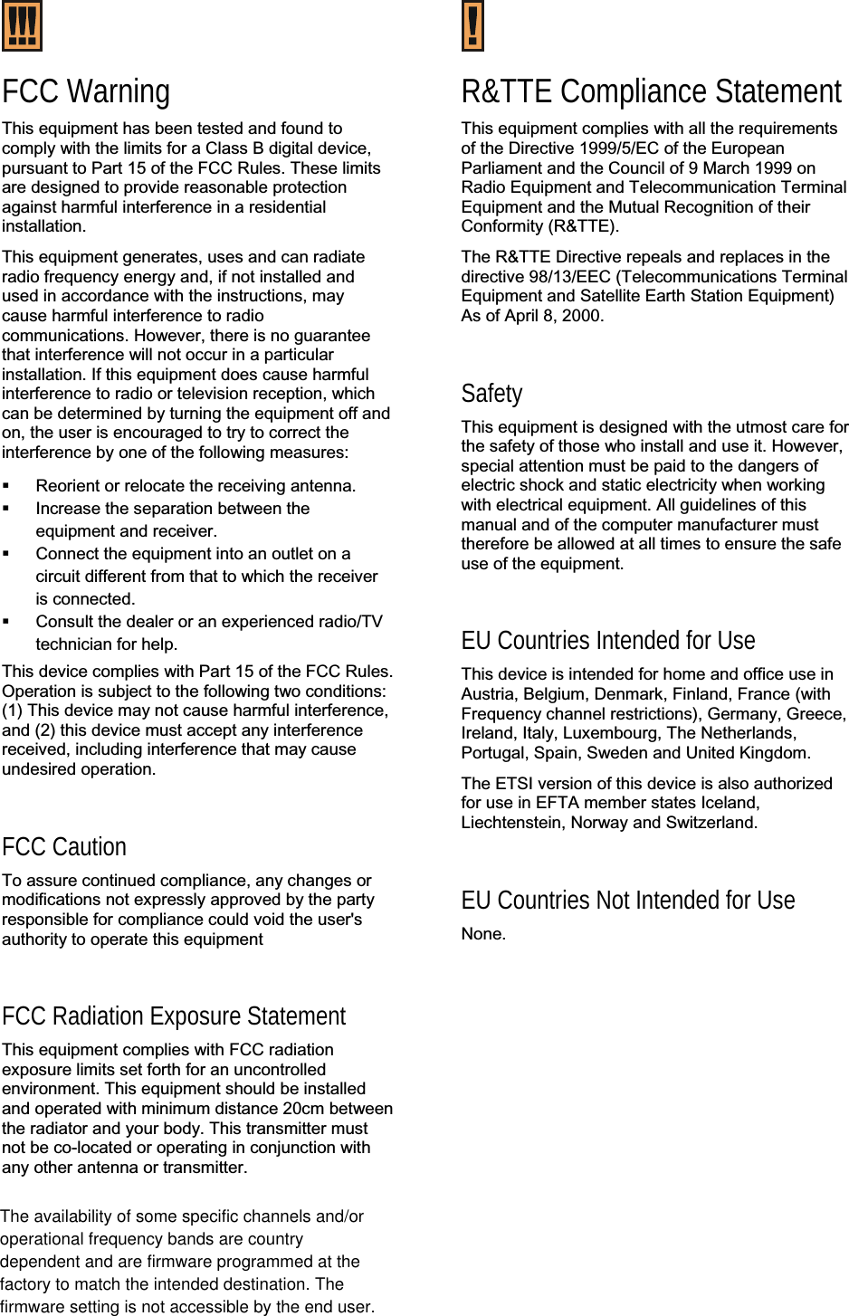
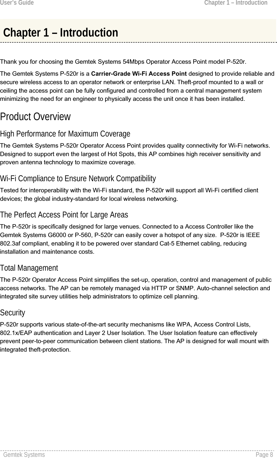
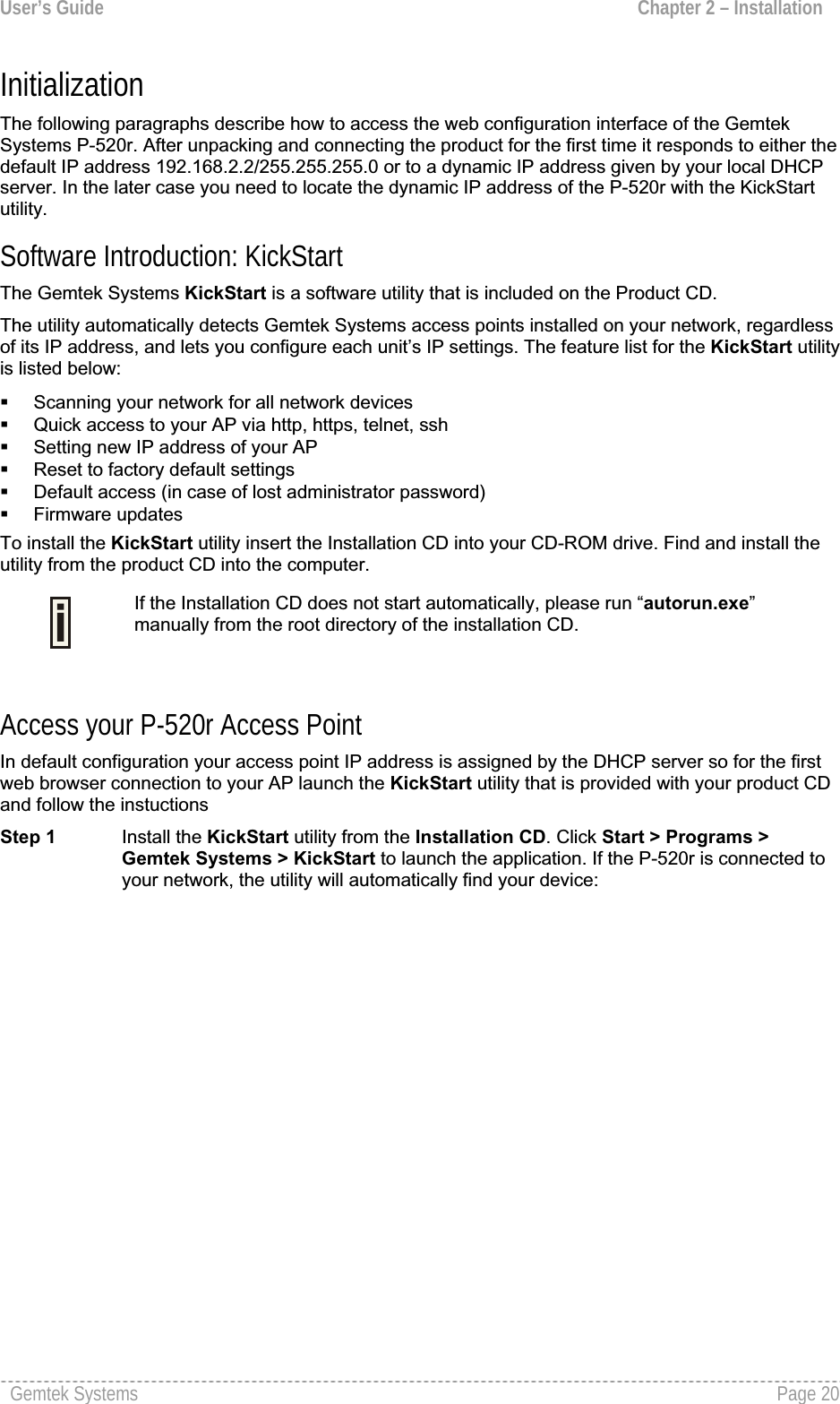
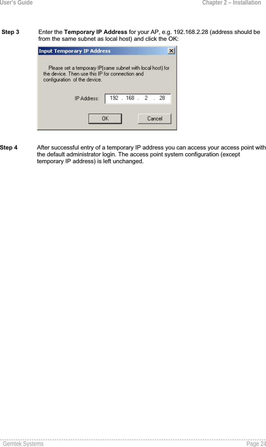
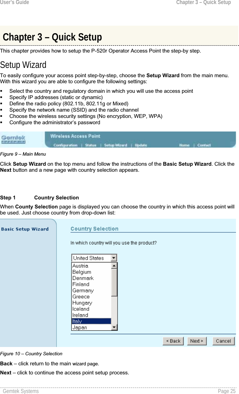
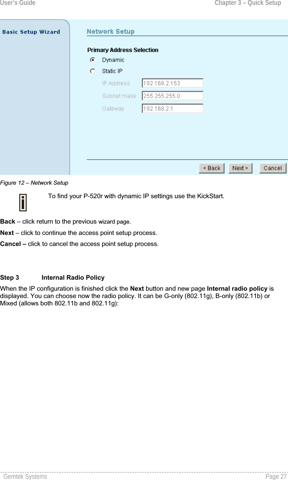
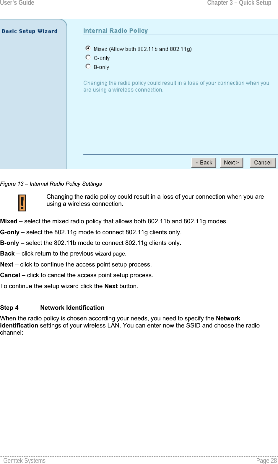
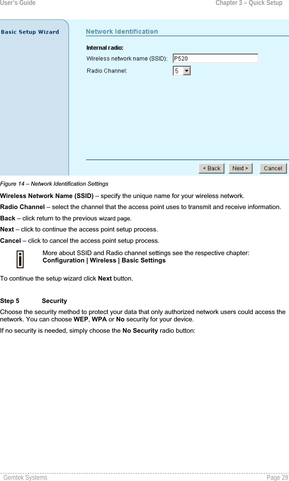
![User’s Guide Chapter 3 – Quick SetupCancel – click to cancel the access point setup process.To continue the setup wizard click the Next button and choose the primary address selection.Step 2 Network SetupThe IP configuration as described below is required for device management purposes. IP addressescan either be retrieved from a DHCP server or configured manually.To setup the device IP configuration manually, choose the Static IP radio button and enter the credentials:Figure 11 – Network Setup SettingsIP Address – specify the access point’s IP address [digit and dots]. When shipped from the factory or reset to factory settings, the AP defaults to a static IP address of 192.168.2.2.Subnet Mask – specify the access point’s subnet mask [digit and dots]. When shipped from the factory or reset to factory settings, the AP defaults to a subnet mask of 255.255.255.0.Gateway – specify the IP address of the access point’s gateway [digit and dots]. When shipped from the factory or reset to factory settings, the AP defaults to a gateway IP address of 192.168.2.1.Select Dynamic radio button, if need that IP address should be assigned by the DHCP server. The static IP settings are displayed but have no affect on the network configuration:Gemtek Systems Page 26](https://usermanual.wiki/GemTek-Technology/AP930301G.Manual/User-Guide-698765-Page-26.png)
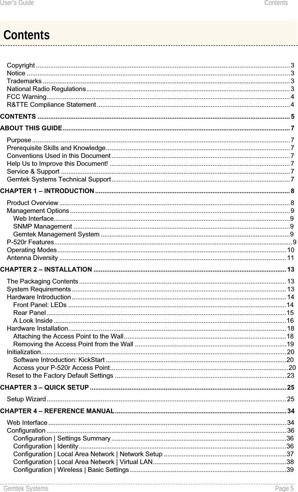
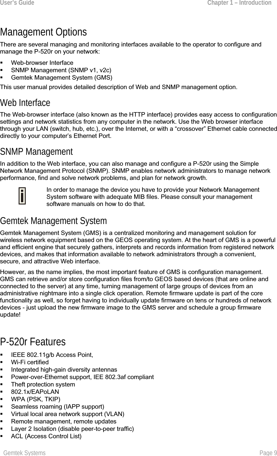
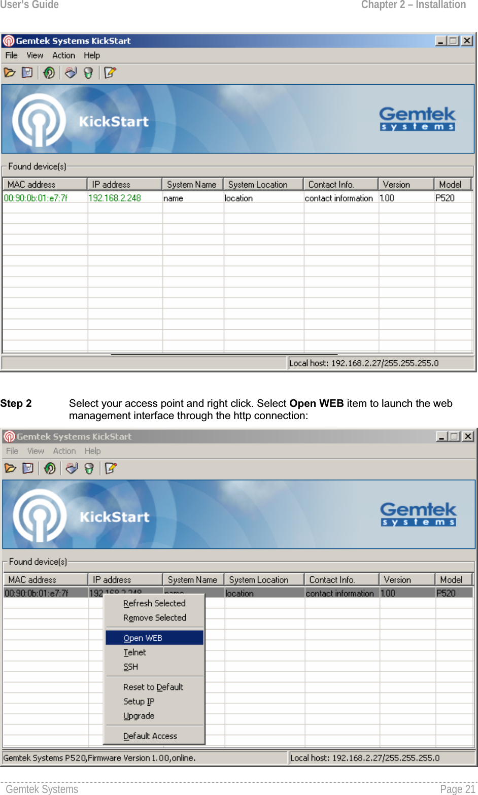
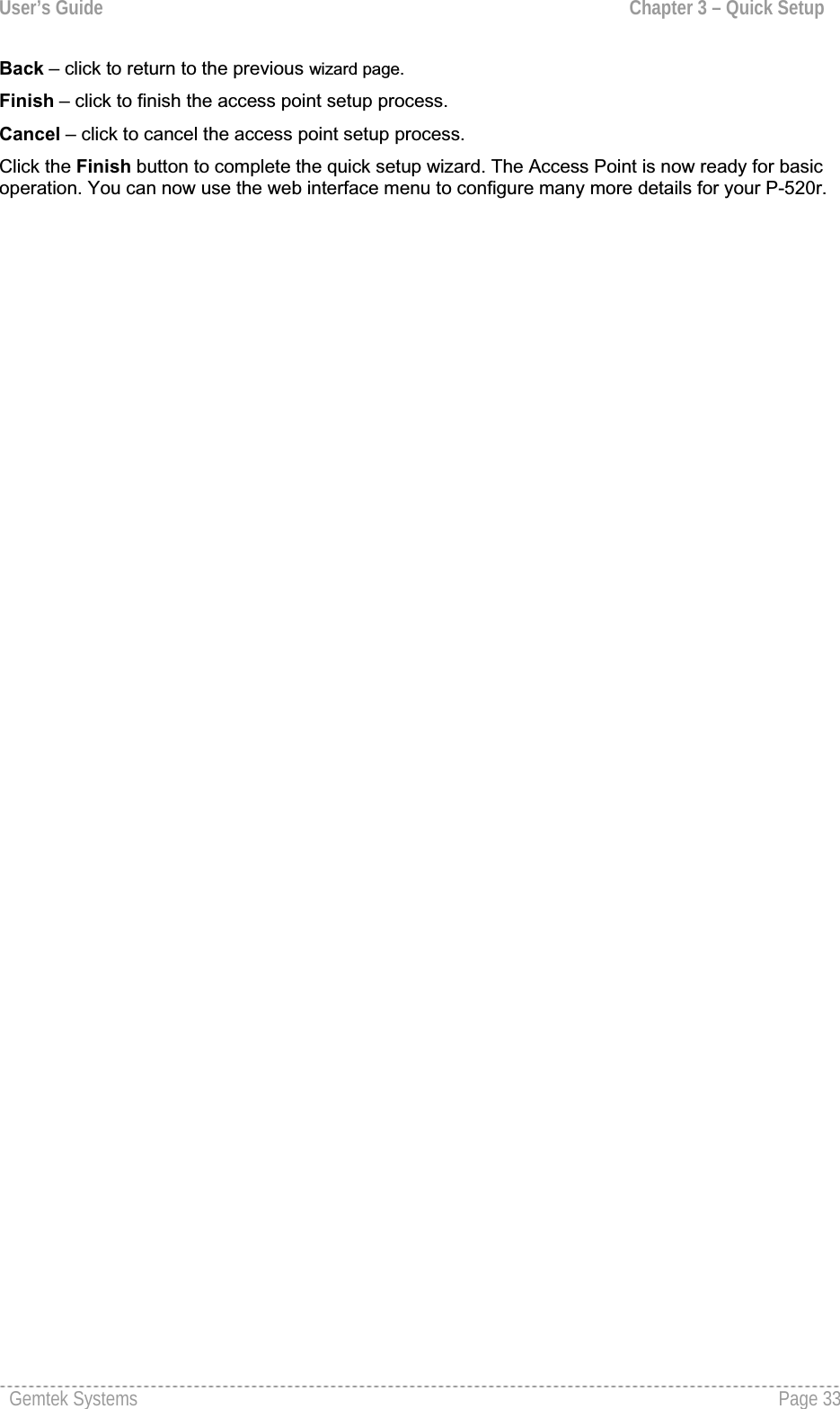
![User’s Guide Chapter 3 – Quick SetupFigure 15 – Security Settings Back – click return to the previous wizard page. Next – click to continue the access point setup process.Cancel – click to cancel the access point setup process.If you ant to choose WEP encryption, just select the Wired Equivalent Privacy (WEP) radio buttonand click Next button to configure the WEP encryption settings. You can then choose the encryptionkey length: Figure 16 – WEP Encryption SettingsKey Length – choose the shared secret’s Key length from drop-down list [64-bits (10 characters)/128-bits (26 characters)].Network Key – specify the shared secret. 5 colon-separated HEX (0-9, A-F, and a-f) pairs (e.g.00:AC:01:35:FF) for the 64-bits WEP encryption; 13 colon-separated HEX (0-9, A-F, and a-f) pairs (e.g. 00:11:22:33:44:55:66:77:88:99:AA:BB:CC) for the 128-bits WEP encryption.Gemtek Systems Page 30](https://usermanual.wiki/GemTek-Technology/AP930301G.Manual/User-Guide-698765-Page-30.png)
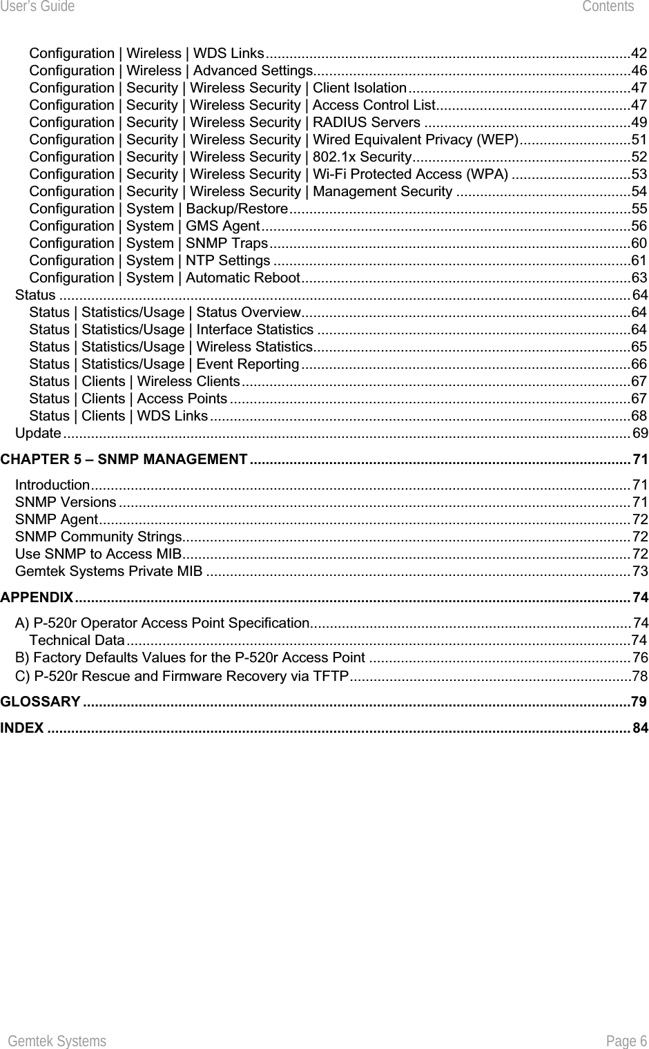
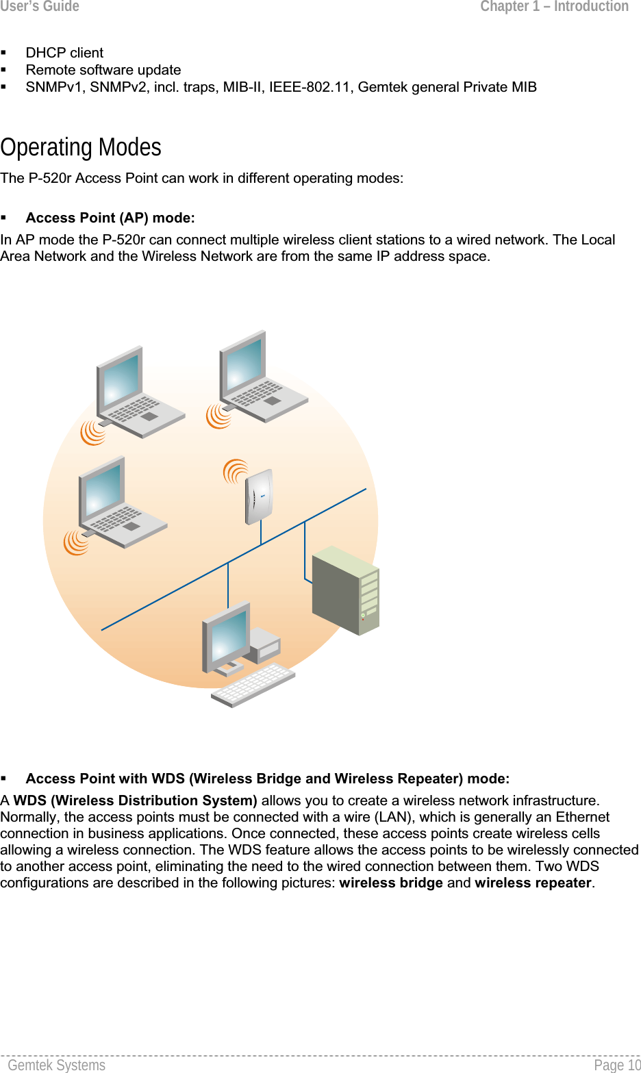
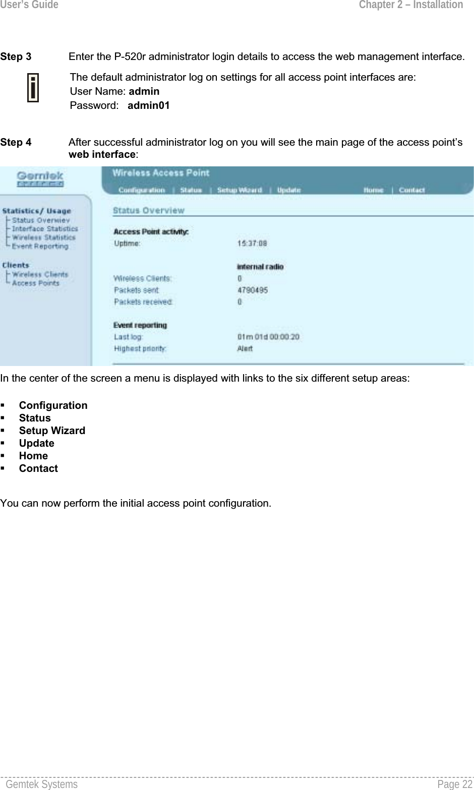
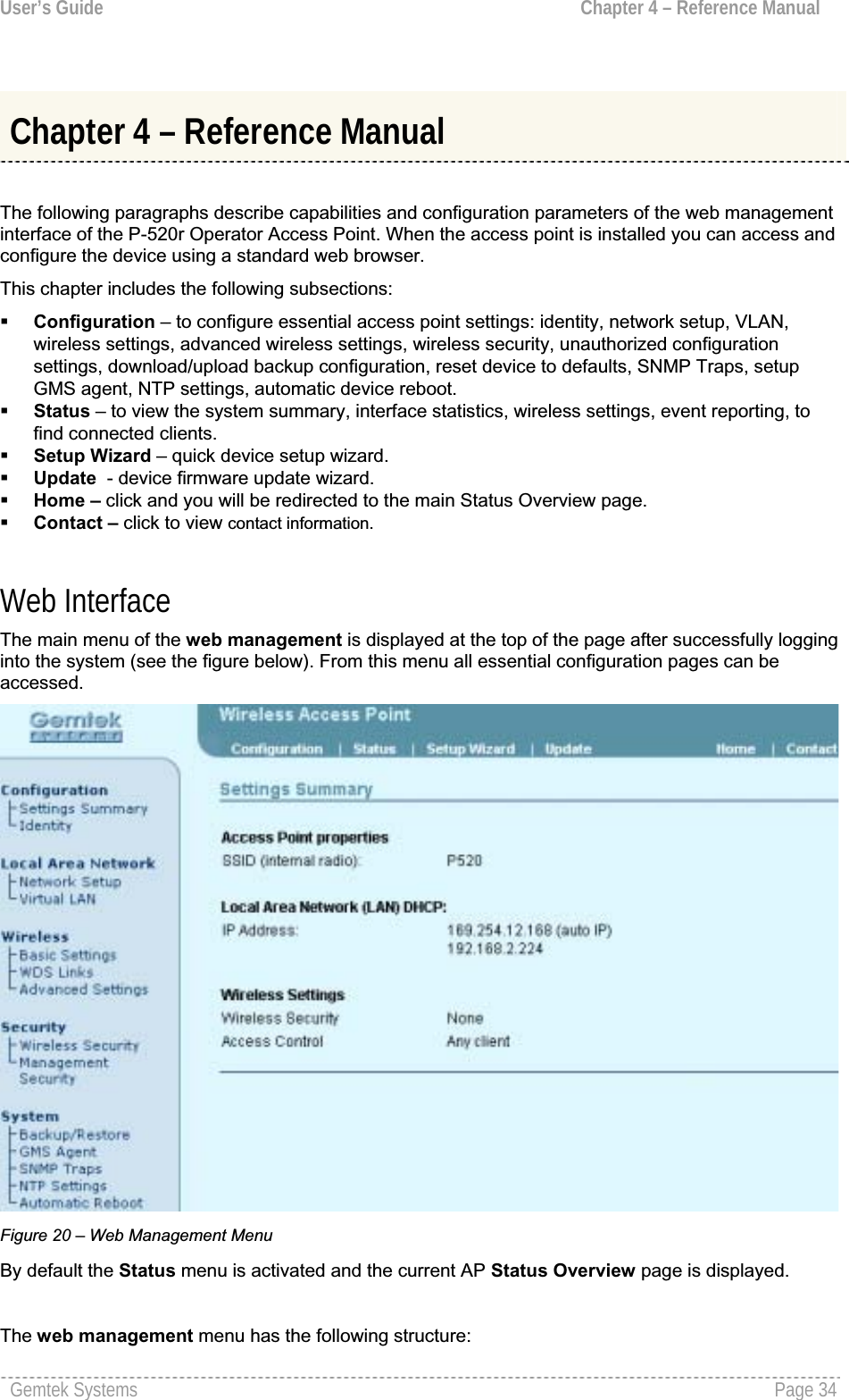
![User’s Guide Chapter 3 – Quick SetupBack – click return to the previous wizard page. Next – click to continue the access point setup process.Cancel – click to cancel the access point setup process.To continue the setup wizard click the Next button and the new Administrator Password Setuppage will appear.More about WEP settings see the respective chapter: Configuration | Security |Wireless Security | Wired Equivalent Privacy (WEP)If you want to choose WPA encryption, just select the Wi-Fi Protected Access (WPA) radio button in the Security page and click the Next button to configure the WPA encryption settings. You can now specify the WPA password phrase:Figure 17 – Wi-Fi Protected Access (WPA) Settings Pre-shared Key – specify WPA pre-shared key [8-63 characters].Re-enter Pre-shared Key – re-enter the WPA pre-shared key to verify its accuracy [8-63 character].Back – click return to the previous wizard page. Next – click to continue the access point setup process.Cancel – click to cancel the access point setup process.To configure WPA without pre-shared key but with dynamic key exchange via RADIUS refer to the chapter Configuration | Security | Wireless Security | Wi-Fi Protected Access (WPA)Step 6 Administrator Password Setup After the security settings have been configured successfully click the Next button and the final step Administrator Password Setup will be displayed. Here you can choose and modify the administrator password to protect your AP from unauthorized configuration.If you want to protect your access point from unauthorized access and configuration, select the Usepassword protection checkbox and specify a password: Gemtek Systems Page 31](https://usermanual.wiki/GemTek-Technology/AP930301G.Manual/User-Guide-698765-Page-31.png)
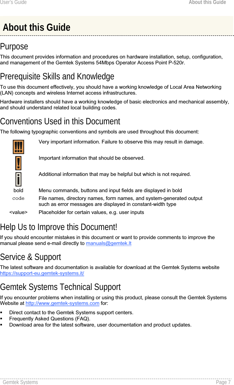
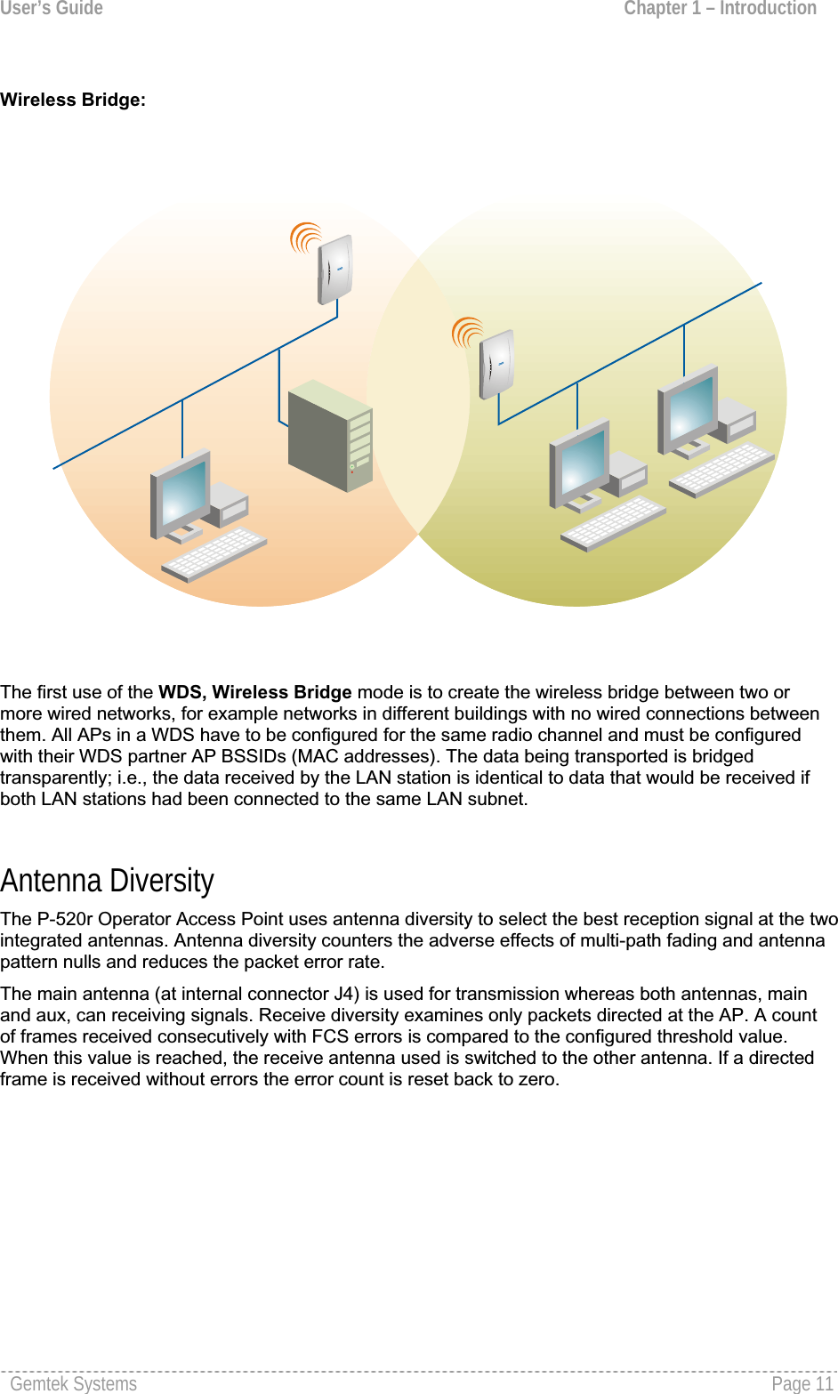
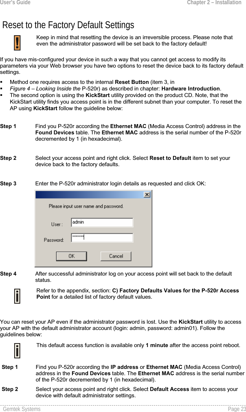
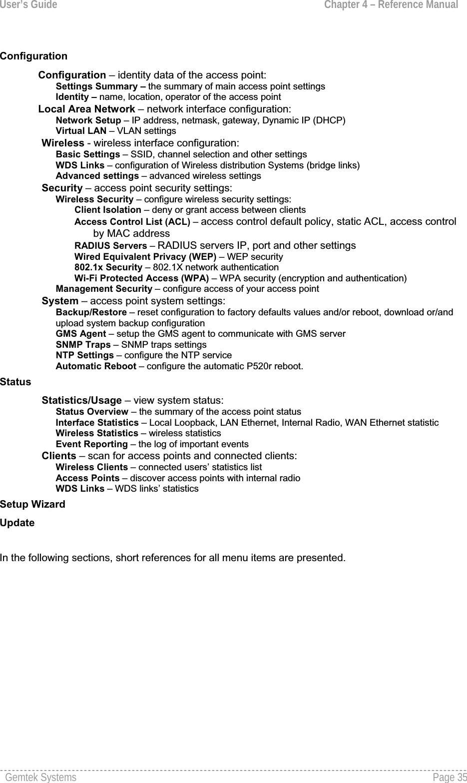
![User’s Guide Chapter 3 – Quick SetupFigure 18 – Administrator Password Setup Settings Password – enter the new password value used for user authentication in the system [4-32 symbols].Confirm Password – re-enter the new password to verify its accuracy.Back – click to return to the main wizard page.Next – click to continue the access point setup process.Cancel – click to cancel the access point setup process.Step 7 Confirm Settings When Administrator’s password configuration is finished, click the Next button to finish the Setup Wizard. You just need to confirm that settings are correct:Figure 19 – Confirm SettingsGemtek Systems Page 32](https://usermanual.wiki/GemTek-Technology/AP930301G.Manual/User-Guide-698765-Page-32.png)
![User’s Guide Chapter 4 – Reference ManualConfigurationConfiguration | Settings SummaryThe Settings Summary page shows important information of the P-520r: its IP address, SSID, wireless security settings and access control status. The page is not configurable but displays the currentsystem configuration only.Figure 21 – Settings SummarySSID – indicates the unique name for your wireless network.IP Address – indicates the IP address of your P-520r. If two addresses are displayed this means that the access point retrieved its IP address dynamicallyvia DHCP. The first IP address is the IGMP IP multicast address; the second IP is given from DHCPserver’s pool.Wireless Security – indicates if security methods are enabled on your access point [None, WEP, WPA, 802.1X].Access Control – indicates access control status [Any client/Selected clients only].Configuration | Identity The identity data of the access point are displayed here. You can use the first three fields Name,Location,Contact to describe the access point. These fields do not influence the behavior of the access point. But are for information purposes only.Gemtek Systems Page 36](https://usermanual.wiki/GemTek-Technology/AP930301G.Manual/User-Guide-698765-Page-36.png)
![User’s Guide Chapter 4 – Reference ManualFigure 22 – Identity Settings Name – specify the administrative name of the access point [string].Location – specify the location where your device is installed [string].Contact – specify the name of the person/company responsible for the P-520r [string]. MAC Address – displays the MAC address of the access point. Cannot be changed.Access Point Type – displays information on your type of access point. Cannot be changed.Firmware Version – displays the version number of the software that controls the access point.Boot Loader Version – displays the boot loader version.Cancel – restore all previous values.Apply – save changed configuration.Configuration | Local Area Network | Network Setup The IP configuration as described below is required for device management purposes. IP addressescan either be retrieved from a DHCP server or configured manually.Figure 23 – Network Setup Settings IP Address – specify the access point’s IP address [digit and dots]. When shipped from the factory or reset to factory settings, the AP defaults to a static IP address of 192.168.2.2.Gemtek Systems Page 37](https://usermanual.wiki/GemTek-Technology/AP930301G.Manual/User-Guide-698765-Page-37.png)
![User’s Guide Chapter 4 – Reference ManualSubnet Mask – specify the access point’s subnet mask [digit and dots]. When shipped from the factory or reset to factory settings, the AP defaults to a subnet mask of 255.255.255.0.Gateway – specify the IP address of the access point’s gateway [digit and dots]. When shipped from the factory or reset to factory settings, the AP defaults to a gateway IP address of 192.168.2.1.If you change the IP address manually, make sure that the chosen IP address is unused and belongs to the same IP subnet as your wired LAN, otherwise you willloose the connection to the P-520r from your current PC.If you enable the DHCP client via a Web browser, the browser will loose the connection after rebooting,because the IP address assigned by the DHCP server is not predictable.If Dynamic is selected the static IP settings are displayed but have no affect on the network configuration. The dynamic IP address and gateway address as assigned by the DHCP server are applied to the system after restart.To find your P-520r with dynamic IP settings use a utility such as Gemtek Systems KickStart.Configuration | Local Area Network | Virtual LAN A Virtual Local Area Network (VLAN) is a mechanism to segregate devices or groups of devices on the same physical LAN. P-520r allows the definition of a VLAN by a VLAN identifier. If you enable the VLAN functionality in the menu Configuration | Local Area Network | Virtual LAN all traffic from the wireless LAN to the LAN will be tagged with the specified VLAN ID. Incoming traffic from the wired LAN not tagged with the appropriate VLAN ID is discarded by the AP. Figure 24 – Virtual Local Area Network (VLAN) Settings To define a VLAN membership on the access point, select the checkbox and enter the VLAN identifier:Figure 25 – Enable Virtual Local Area Network (VLAN)VLAN id – specify the ID for your VLAN network [1 to 4094]. Wireless client devices connected to the AP are grouped into this VLAN. Cancel – restore all previous values.Apply – save changed configuration.Gemtek Systems Page 38](https://usermanual.wiki/GemTek-Technology/AP930301G.Manual/User-Guide-698765-Page-38.png)
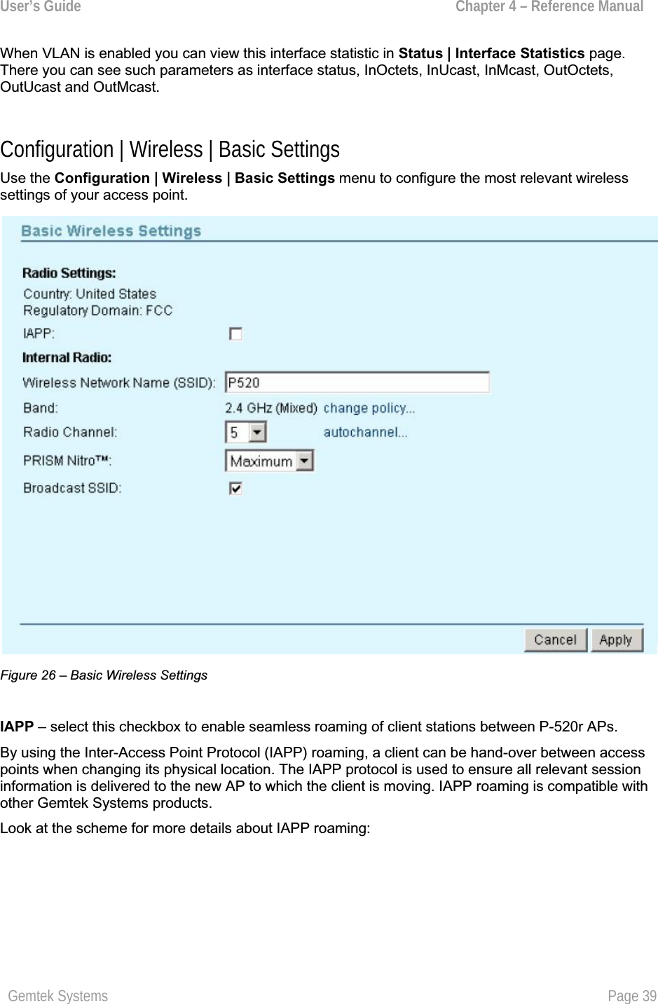
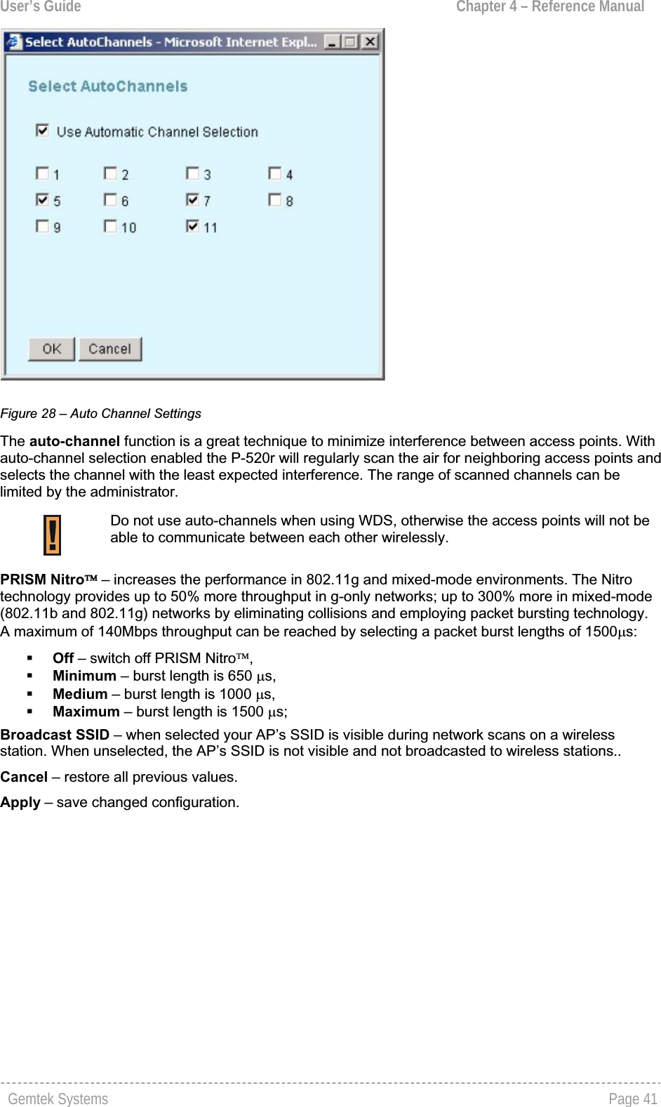
![User’s Guide Chapter 4 – Reference ManualIAPP RoamingAP1 AP2ClientRADIUS ServerFigure 27 – IAPP Roaming SchemeThe wireless client is switched from AP1 to AP2 when entering the coverage area of the new accesspoint (AP2). The roaming is performed without client re-authentication. The IAPP protocol ensures to inform the old AP1 of the new client association. The AP1 then stops the client RADIUS session, and the AP2 starts the client’s session with the RADIUS.IAPP roaming requires that all access points share the same SSID. Wireless Network Name (SSID) – is a unique name for your wireless network [1-32 symbols]. The default SSID is "P520" but you should change this to a personal wireless network name. The SSID is important for client stations when connecting to the access point. All client stations must have their client SSID settings configured and must use the same SSID. Band – click on the change policy… link and choose the policy of internal radio mode [Mixed/G-only/B-only].Changing the radio policy could result in a loss of your connection when you are using a wireless connection.Radio Channel – select the channel that the access point uses to transmit and receive information. Multiple frequency channels are used to avoid interference between nearby access points. If you wish to operate more than one access point in overlapping coverage areas, we recommend a distance of at least four channels between the chosen channels. For example, for three access points in closeproximity choose channels 1, 6 and 11. Click on the autochannel… link and a pop-up window with auto channel settings will appear. You can now select a list of preferred channels: Gemtek Systems Page 40](https://usermanual.wiki/GemTek-Technology/AP930301G.Manual/User-Guide-698765-Page-40.png)
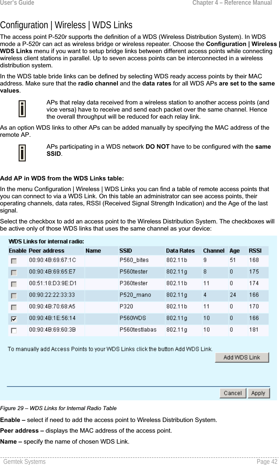
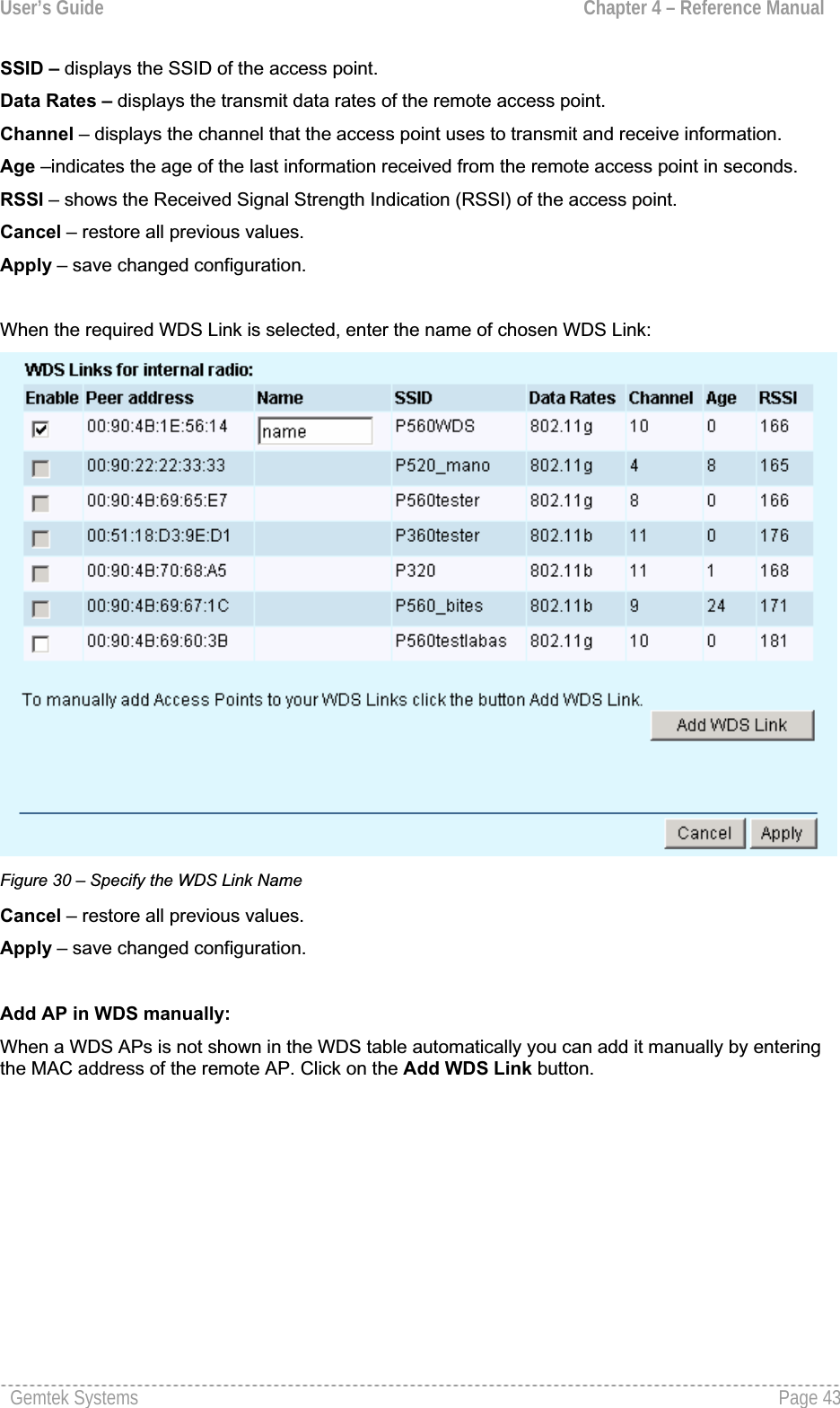
![User’s Guide Chapter 4 – Reference ManualConfiguration | Wireless | Advanced Settings For normal operation the following default settings do not need to be modified. Changing the P-520r advanced settings requires expert knowledge of the 802.11 protocol and the radio functionality.The configuration menu Configuration | Wireless | Advanced Settings allows administrators to change low level radio parameters and antenna diversity settings: Figure 32 – Advanced Wireless Settings Operational Rate Set – this setting specifies the set of Supported and Basic data rates at which the station may transmit data. Each rate shall be within the range from 2 to 127, corresponding to data rates in increments of 500 kb/s from 1 Mb/s to 63.5 Mb/s, and shall be supported for receiving data.This value is reported in transmitted Beacon, Probe Request, Probe Response, Association Request,Association Response, Reassociation Request, and Reassociation Response frames, and is used to determine whether a BSS with which the station desires to synchronize is suitable. Operational rate set is defined as hexadecimal string where highest bit of each digit represents if Supported rate is the Basic rate (basic rate = supported rate | 0x80, where “|” means “bitwise or”operation).Beacon Period – this setting specifies the amount of time between beacons in milliseconds. A beacon is a packet broadcast by the access point to synchronize the wireless network.RTS Threshold – this setting specifies the maximum packet size beyond which the Wireless LANCard invokes its RTS/CTS mechanism. Packets that exceed the specified RTS threshold trigger the RTS/CTS mechanism. The NIC transmits packets smaller than this threshold without using RTS/CTS [[0-2347] default: 2347 (2347 means that RTS is disabled)].Fragmentation Threshold – the fragmentation threshold, specified in bytes, determines whetherpackets will be fragmented and at what size. On an 802.11 wireless LAN, packets exceeding thefragmentation threshold are fragmented, i.e., split into, smaller units suitable for the circuit size.Packets smaller than the specified fragmentation threshold value are not fragmented [[256-2346]default: 2346 (2346 means that fragmentation is disabled)].Enable TX and RX Diversity – choose this option to enable or disable the antenna diversity. Gemtek Systems Page 46](https://usermanual.wiki/GemTek-Technology/AP930301G.Manual/User-Guide-698765-Page-46.png)
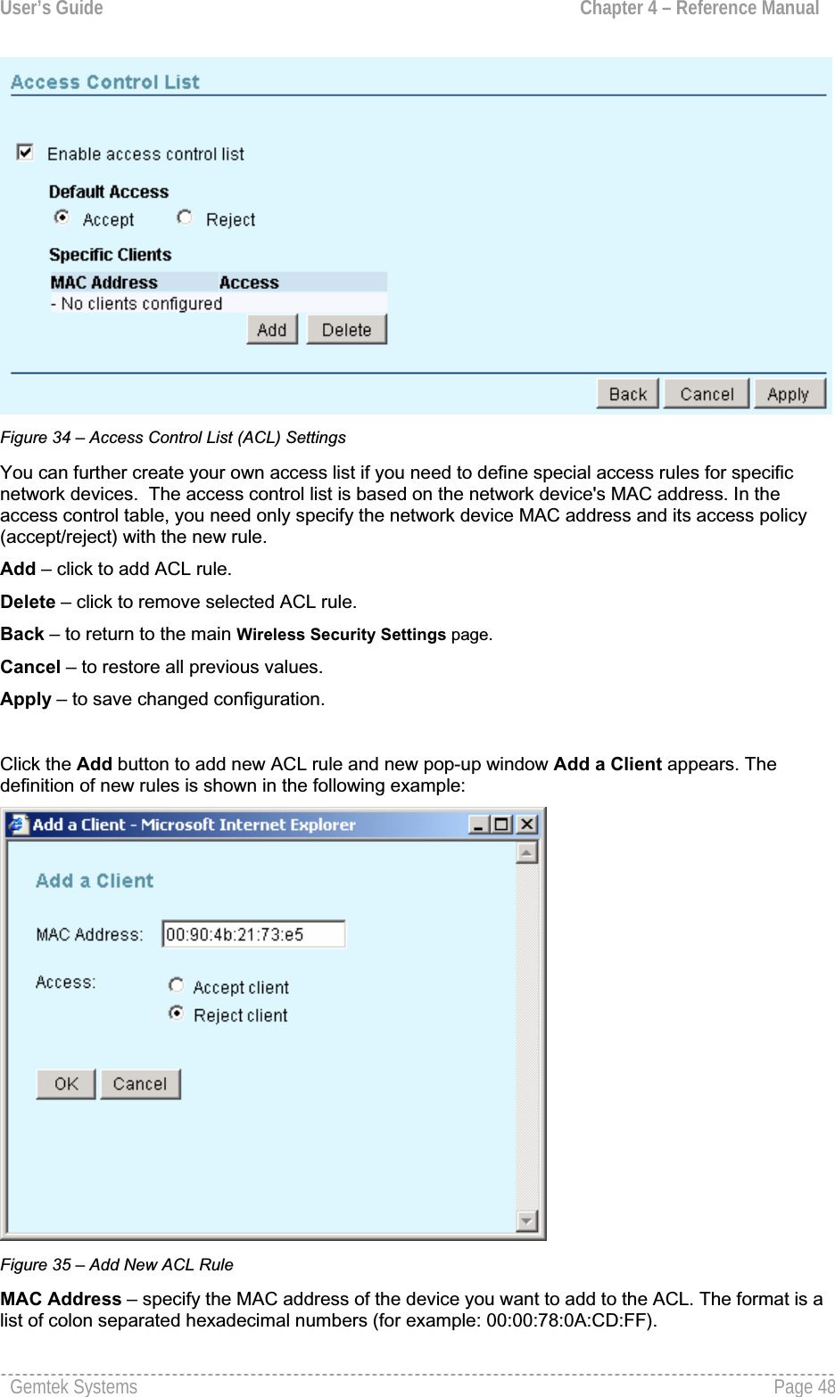
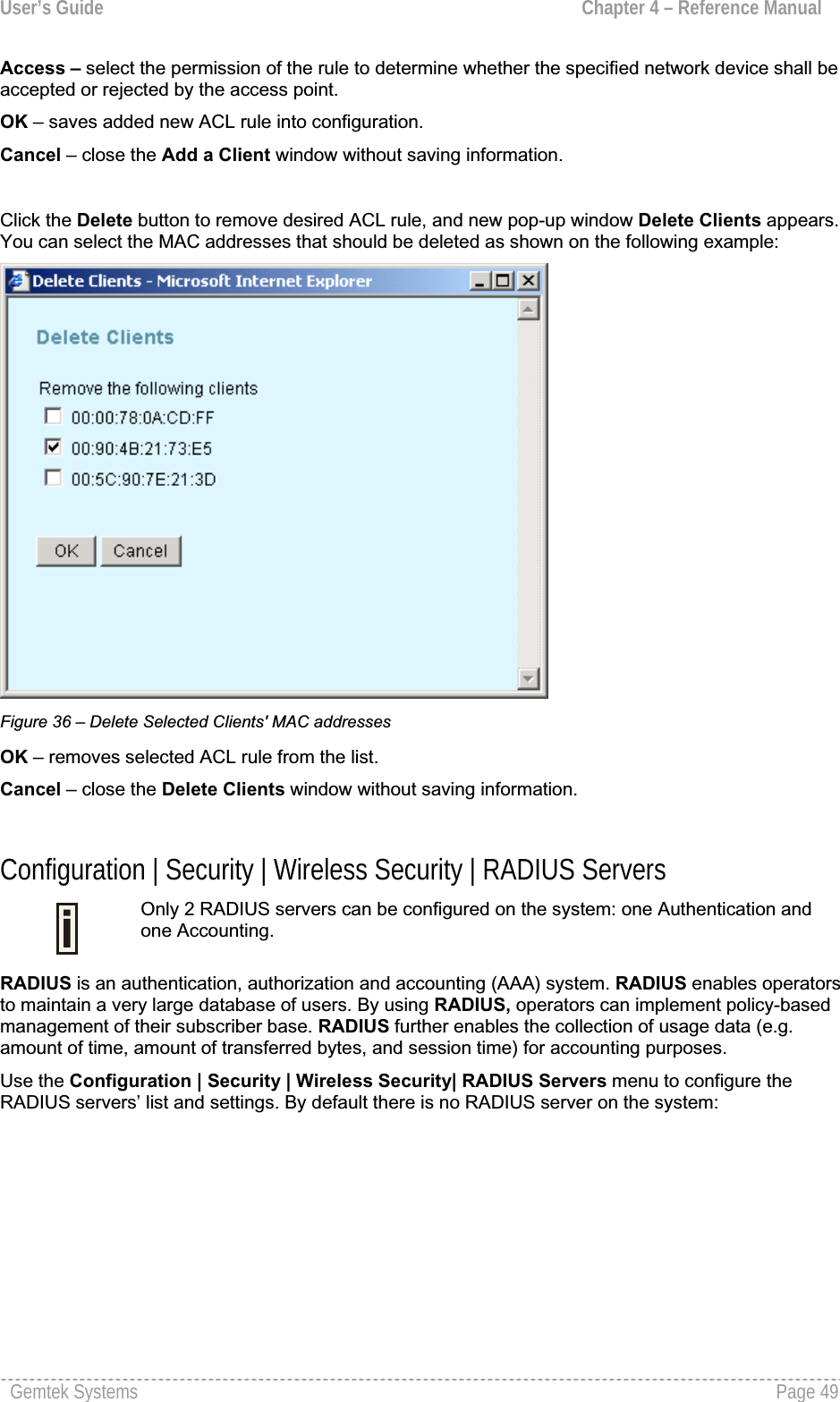
![User’s Guide Chapter 4 – Reference ManualUse the antenna diversity to select the best reception signal at the two integrated antennas. The main antenna is used for transmission whereas both antennas, primary and secondary, can receivesignals. Receive diversity examines only packets directed at the AP. A count of frames receivedconsecutively with FCS errors is compared to the configured threshold value. When this value isreached, the receive antenna used is switched to the other antenna. If a directed frame is receivedwithout errors the error count is reset back to zero. If the antenna diversity option is enabled, the Antenna Used To Transmit and AntennaUsed To Receive settings have no effect. Antenna Used To Transmit – choose the single antenna for transmitting [primary/secondary].Antenna Used To Receive – choose the single antenna for receiving [primary/secondary].Cancel – to restore all previous values.Apply – to save changed configuration.Configuration | Security | Wireless Security | Client Isolation Use the Configuration | Security | Wireless Security| Client Isolation menu to configure the layer 2 user isolation feature. Select the Use Client Isolation checkbox to enable Layer 2 wireless client separation. In this case connected wireless stations are not able to communicate with each other. The client stations are isolated on MAC address level. Figure 33 – Client Isolation SettingsBack – to return to the main Wireless Security Settings page.Cancel – to restore all previous values.Apply – to save changed configuration.Configuration | Security | Wireless Security | Access Control List In the Access Control Settings page (Access Control List (ACL) menu under the Configuration | Security | Wireless Security) you can specify default access policy for the Wireless device interfaceor define special access rules. To enable Access Control List select the Enable access control listcheckbox.Default Access: select Accept to allow all mobile clients to access this access point or Reject toprevent all mobile clients from accessing your access point. Clients may also be subject to rules in the Access control table.Gemtek Systems Page 47](https://usermanual.wiki/GemTek-Technology/AP930301G.Manual/User-Guide-698765-Page-47.png)
![User’s Guide Chapter 4 – Reference Manual Figure 37 – RADIUS Servers' Settings Re-authentication Time – specify the number of seconds after which the access point re-authenticates client stations [0-2147483647]. The default value is 3600 seconds. If 0 is entered it means that stations will not have to re-authenticate as long as they are connected.IP address – displays RADIUS server’s IP address.Port Number – displays RADIUS server’s port number.Type – displays RADIUS server’s type. Add – click to add RADIUS server.Delete – click to remove selected RADIUS server.Back – to return to the main Wireless Security Settings page.Cancel – to restore all previous values.Apply – to save changed configuration.In the default configuration no RADIUS servers are define on the system. Click the Add button to addnew RADIUS server and new pop-up window Add RADIUS server appears. You can define the RADIUS server’s parameters as shown on the following example: Figure 38 – Add RADIUS ServerServer Type – select the RADIUS server’s type [authentication/accounting].Gemtek Systems Page 50](https://usermanual.wiki/GemTek-Technology/AP930301G.Manual/User-Guide-698765-Page-50.png)
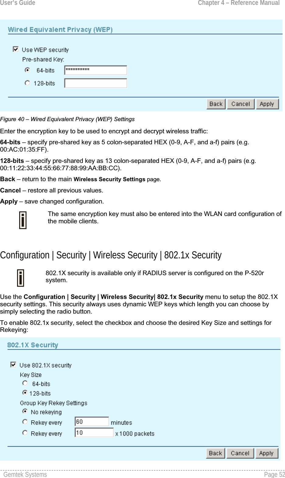
![User’s Guide Chapter 4 – Reference ManualIP Address – enter the RADIUS server IP address [digit and dots].UDP Port – specify the network port used to communicate with RADIUS [1-65535]. Default: 1812.The port default value is 1812 in accordance with RFC 2865 " RemoteAuthentication Dial-in User Service (RADIUS)".Secret – specify the shared secret string that is used to encrypt data frames used for RADIUS servers[4-64 symbols].Confirm Secret – re-enter the RADIUS secret to verify its accuracy.OK – saves added new RADIUS server into configuration.Cancel – close the window without saving information.Click the Delete button to delete desired RADIUS server, and new pop-up window Delete RADIUSServers appears. You can select the RADIUS server that should be deleted as shown on thefollowing example: Figure 39 – Delete RADIUS serverOK – removes selected RADIUS servers from the system.Cancel – close the window without saving information.Configuration | Security | Wireless Security | Wired Equivalent Privacy (WEP) WEP is a data privacy mechanism based on a 64-bit or 128-bit shared key algorithm as described in the IEEE 802.11 standard. Static WEP uses a symmetric scheme where the same key and algorithmare used for both encryption and decryption of data. Use the Configuration | Security | Wireless Security| Wired Equivalent Privacy (WEP) menu to configure the WEP encryption.The checkbox Use WEP Encryption defines if encryption will be used or not. To enable WEPencryption, select this checkbox:Gemtek Systems Page 51](https://usermanual.wiki/GemTek-Technology/AP930301G.Manual/User-Guide-698765-Page-51.png)
![User’s Guide Chapter 4 – Reference ManualFigure 41 – 802.1X Security SettingsKey Size and Group Rekeying unavailable when using WEP security.64-bits – indicates that a 64-bit key is chosen for 802.1x security. 128-bits – indicates that a 128-bit key is chosen for 802.1x security.No rekeying – indicates that Group Key will not be changed dynamically.Rekey every … minutes – specify the time period in minutes, after which the group key will beupdated [1-71582788]. Default value is 60 minutes.Rekey every … x1000 packets – specify the number of transmitted packets, per 1000 packets, after which the group key value will be updated [1-4294967295]. Default value is 10x1000 packets.Configuration | Security | Wireless Security | Wi-Fi Protected Access (WPA) Wi-Fi Protected Access provides a higher level of protection for wireless LAN client stations as it includes methods for mutual authentication, strong encryption, and data integrity. WPA takes theoriginal master key only as a starting point and derives its encryption keys dynamically from thismaster key. WPA regularly changes and rotates the encryption keys so that the same encryption key is never used twice. Key exchange is done automatically transparent to the user.To enable the WPA security for your WLAN you need:An access point that has WPA support like the Gemtek Systems P-520rA wireless network card with WPA ready driver A supplicant that supports WPA (e.g. Windows XP client)To configure the WPA with pre-shared key security on the P-520r use the Configuration | Security | Wireless Security| Wi-Fi Protected Access (WPA) menu, select the WPA with pre-shared keysecurity method and enter the shared secret:Figure 42 – WPA with Pre-shared Key SettingsPre-shared Key – specify the pre-shared key for WPA security [8-63 characters].Re-enter Pre-shared Key – re-enter pre-shared key to verify its accuracy. Gemtek Systems Page 53](https://usermanual.wiki/GemTek-Technology/AP930301G.Manual/User-Guide-698765-Page-53.png)
![User’s Guide Chapter 4 – Reference ManualThe pre-shared key must match the one configured on your WLAN client stations.Back – return to the main Wireless Security Settings page.Cancel – restore all previous values.Apply – save changed configuration.WPA with RADIUS server makes use of external AAA (RADIUS) server to generate and exchange dynamic WPA keys between P-520r and the client stations. To configure WPA with a RADIUS server select the WPA with RADIUS server security method radio button and enter the Group Key Rekeysettings:Figure 43 – WPA with RADIUS Server SettingsNo rekeying – indicates that Group Key will not be rekeyed.Rekey every … minutes – specify amount of minutes and WPA automatically will generate a newRekey every … minutes – specify the time period in minutes, after which the group key will beupdated [1-71582788]. Default value is 60 minutes.Rekey every … x1000 packets – specify the number of transmitted packets, per 1000 packets, after which the group key value will be updated [1-4294967295]. Default value is 10x1000 packets.Update Group Key if station leaves BSS – when selected, the group key value will be updated if wireless client leaves BSS. Configuration | Security | Wireless Security | Management Security Use the Configuration | Security | Wireless Security | Management Security menu for changingthe administrator’s password and to lock the access point for any further configuration changes.The default administrator settings for all access point interfaces are:username - adminpassword - admin01The username is not configurable parameter, so it cannot be changed.Gemtek Systems Page 54](https://usermanual.wiki/GemTek-Technology/AP930301G.Manual/User-Guide-698765-Page-54.png)
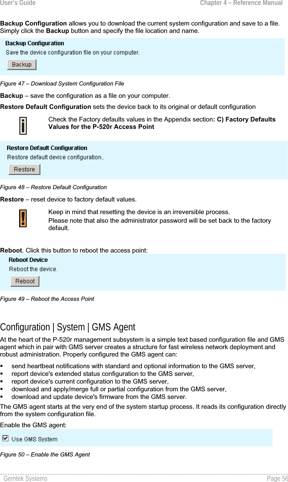
![User’s Guide Chapter 4 – Reference ManualFigure 44 – Change Administrator's PasswordNew Password – specify new password value used for user authentication in the system [4-32characters].Confirm Password – re-enter the new password to verify its accuracy.Change Password – changes new specified administrator’s password.The password is also the SNMP Read-write community string. If the password ischanged the SNMP community string will be changed as well. Use Lock Access Point to prevent modifications to the current device configuration.Figure 45 – Lock Access PointLock Access Point – click the button to lock the P-520r.This action denies system configuration modifying. You will not be able to configure any of device settings. To unlock the access point you need the physical access to the P-520r and press the reset button on the device for 1 second.Keep in mind that reset button will set the administrator password back to default: User Name: adminPassword: admin01Configuration | System | Backup/Restore To restore s saved system configuration, set factory defaults or download current system configuration use the Backup/Restore menu.Restore Configuration allows you to upload a backup configuration from disk to the P-520r. Simplyselect the configuration file from disk and click upload:Figure 46 – Upload System Configuration FileBrowse – specify file you want to upload location.Upload – upload system configuration on the system.Gemtek Systems Page 55](https://usermanual.wiki/GemTek-Technology/AP930301G.Manual/User-Guide-698765-Page-55.png)
![User’s Guide Chapter 4 – Reference ManualUse GMS System – select this checkbox to enable association of the device with GMS server.Setup connection to GMS server settings:Figure 51 – Connection to GMS server settingsUse Persistent – select the checkbox to make a persistent connection to the GMS server. If enabled,the connection to the GMS server will be kept persistent; if disabled, the connection will be established and subsequently closed after all server responses are processed for every heartbeatnotification.Timeout – specify the maximum number of seconds to wait for a response from the GMS serverbefore considering the connection as having timed out. Default: 60 seconds.Setup multicast settings:Figure 52 – Multicast SettingsIP address – specify the IP multicast group address to listen on during automatic GMS serverdiscovery. Default: 224.0.6.128. Port – specify the port to bind to when listening on an IP multicast group during automatic GMSserver discovery [1-56635]. Default: 45144.Interface Name – specify the name of the interface to bind to when listening on an IP multicast groupduring automatic GMS server discovery [default: br0]. The interface is optional, but it is highly recommended to define it. If no interface is provided, GMS agent will try to bind on all interfaces. Thiswill succeed only if default or multicast route is configured on the system. Otherwise GMS agent will keep trying to bind and report errors to system log. It is not recommended to change default multicast settings. In case incorrectsettings are specified, the device will not be able to discover the GMS server location.Specify the authentication settings:Figure 53 – specify GMS Authentication Settings Certificate Path – specify the name of GMS client certificate PKCS12 file [file name]. It should be stored in /usr/etc/ directory on device.Gemtek Systems Page 57](https://usermanual.wiki/GemTek-Technology/AP930301G.Manual/User-Guide-698765-Page-57.png)
![User’s Guide Chapter 4 – Reference ManualPassword – specify the password for certificate PKCS12 file [string]. Only used if the certificate key is encrypted.Identifier – specify the unique identifier used for client authentication [all ASCI characters].Gemtek Systems Page 58](https://usermanual.wiki/GemTek-Technology/AP930301G.Manual/User-Guide-698765-Page-58.png)
![User’s Guide Chapter 4 – Reference ManualSpecify the alarms settings:Figure 54 – Specify the Alarm Settings Use Alarms – select the checkbox if need to enable the alarm gathering.Level – specify the message level [emergency/alert/critical/error/warning/notice/info/debug].Messages that have this level or any level of greater importance are considered alarms and are reported to the RCMS agent. Default – errors.Specify the heartbeat settings: Figure 55 – the Heartbeat Settings URL – specify the URL of the GMS server that heartbeat notifications are sent to (and, subsequently,server responses are read from and processed)Interval – specify the interval, in seconds, between subsequent heartbeat notifications. Default: 30. You can configure the device monitoring specifying the Object Identifier (OID) and the name of the statistic to gather the information from. Simply click Add button under the table and specify settings: Figure 56 – Add the OID Name – specify optional attribute name.Object Identifier (OID) – specify the local SNMP OID to gather the information from [SNMP OID] Up to 16 OIDs can be added on the system.OK – click to add OID in the table. Gemtek Systems Page 59](https://usermanual.wiki/GemTek-Technology/AP930301G.Manual/User-Guide-698765-Page-59.png)
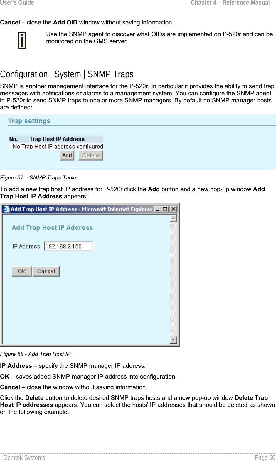
![User’s Guide Chapter 4 – Reference ManualFigure 59 – Delete Trap Host IPOK – removes selected SNMP manager IP addresses from the system.Cancel – close the window without saving information.Configuration | System | NTP Settings The NTP (Network Time Protocol) is used to synchronize the clock of the access point to a selectedtime reference. You can synchronize the system clock settings using the Configuration | System | NTP Settings menu:Figure 60 – NTP Settings Local Time – displays the current system date and time. Enable NTP – select this option if you want to specify auto time settings (using NTP server).Time Zone (+/-hh:mm) – specify time zone for NTP time [-12.00 – +12.00]. The NTP server returnsGMT + 00.00 time if not specified otherwise.The Time Zone is taken into account for the time displayed in the managementGUI, however the system works on GMT (UTC)Gemtek Systems Page 61](https://usermanual.wiki/GemTek-Technology/AP930301G.Manual/User-Guide-698765-Page-61.png)
![User’s Guide Chapter 4 – Reference ManualNTP Server – displays the NTP server.Cancel – click the button to cancel changes.Apply – click the button to save auto time and date settings.To add the NTP host, click Add button under the NTP server’s table and a new pop-up window AddNTP Server appears:Figure 61 – Add a New NTP Server NTP Server – specify the trusted NTP server host [1-128].OK – saves added NTP host into configuration.Cancel – close the window without saving information.There is a possibility to add an additional NTP service host. The secondary NTP server will be used if connection to the previously defined NTP server is lost.Click the Delete button to delete desired NTP hosts and a new pop-up window Delete NTP Serverappears. You can select the hosts’ IP addresses that should be deleted as shown on the followingexample:Gemtek Systems Page 62](https://usermanual.wiki/GemTek-Technology/AP930301G.Manual/User-Guide-698765-Page-62.png)
![User’s Guide Chapter 4 – Reference ManualFigure 62 – Delete a NTP serverOK – removes selected NTP host from the system.Cancel – close the window without saving information.Configuration | System | Automatic Reboot The Automatic Reboot feature allows to reboot the P-520r device automatically at the scheduled time. Figure 63 – Automatic Reboot ConfigurationEnable Automatic Reboot – select this option if you want to activate Automatic Reboot function and specify settings. Reboot date (yyyy-mm-dd) – specify the reboot date value [year-month-day]. Reboot time (hh:mm) – specify the reboot time [hours:minutes].Reboot every (hours) – specify the time period in hours for every next reboot [0-1000].Cancel – click the button to cancel changes.Apply – click the button to save automatic reboot settings.Gemtek Systems Page 63](https://usermanual.wiki/GemTek-Technology/AP930301G.Manual/User-Guide-698765-Page-63.png)
![User’s Guide Chapter 4 – Reference ManualStatusStatus | Statistics/Usage | Status OverviewUse the Status | Statistics/Usage | Status Overview menu for a summary of status information of your access point. Figure 64 – Status OverviewUptime – indicates the time, expressed in hours, minutes and seconds since last reboot[hours:minutes:seconds].Wireless Clients – indicates the total number of currently connected client stations. Click on thehyperlink Status | Clients | Wireless Clients to see more details for individual clients. Packets Sent – indicates the data volume transmitted to the wireless LAN since reboot.Packets Received – indicates the volume of data received since reboot. Last Log – indicates the time when the access point has sent the most recent event message.Highest Priority – shows the priority level of the last event [Emergency/Alert/Critical/Error/Warning/Notice/Info/Debug].Status | Statistics/Usage | Interface Statistics Use the Status | Statistics/Usage | Interface Statistics menu for a summary of interface statisticsGemtek Systems Page 64](https://usermanual.wiki/GemTek-Technology/AP930301G.Manual/User-Guide-698765-Page-64.png)
![User’s Guide Chapter 4 – Reference ManualFigure 65 – Interface StatisticsInterface – indicates a unique name for each interface.Status – shows the current operational state of the interface [up/down].InOctets – indicates the amount of received bytes on the interface, including framing characters.InUcast – totals unicast frames received at the port excluding discards. InMcast – totals multicast frames received at the port excluding discards. OutOctets – shows the total transmitted frames of the interface in bytes, including framing characters.OutUcast – totals unicast frames transmitted from the port including discards.OutMcast – totals multicast frames transmitted from the port including discards.Status | Statistics/Usage | Wireless Statistics Use the Status | Statistics/Usage | Wireless Statistics menu to view information regarding datatraffic for the Wireless interface.Figure 66 – Wireless StatisticsTransmitted Fragments – displays the total of transmitted fragmented frames.Transmitted Multicasts – displays the total of transmitted multicast frames. Transmitted Frame Count – displays count of successfully transmitted MSDU (MAC Service Data Units).Failed Packets – displays the total of not transmitted MSDU.Retry Count – displays the number of successfully transmitted MSDU after one or more retransmissions.Multiple Retry Count – displays the number of successfully transmitted MSDU after more than one retransmissions.Duplicate Frames – displays the total of duplicate frames. Gemtek Systems Page 65](https://usermanual.wiki/GemTek-Technology/AP930301G.Manual/User-Guide-698765-Page-65.png)
![User’s Guide Chapter 4 – Reference ManualRTS Success Count – displays the total of successfully received RTS packets. RTS Failure Count – displays total of not received RTS packets.ACK Failure Count – displays total of expected but not received ACK (acknowledgement) frames. Received Fragment Count – displays total of each successfully received MPDU (MAC Protocol DataUnit) of type Data or Management.Received Multicasts Count – displays the total of MSDU, received with the multicast bit set in the destination MAC address.FCS Errors – displays count of FCS (Frame Check Sequence) errors in received MPDU. WEP Undecryptable – displays the number of not decrypted frames.Status | Statistics/Usage | Event Reporting The event reporting system informs about internal services and provides debug messages in case of malfunctions or network problems. The trace system can help operators to locate mis-configurationsand system errors. Use the Status | Statistics/Usage | Event Reporting menu to view current syslogmessages in case of troubleshooting of one of the services:Figure 67 – Event ReportingReset Eventlog – delete all displayed logged messages.Report Level – shows how important the event (or how critical the error) is [Emergency/Alert/Critical/Error/Warning/Notice/Info/Debug].Gemtek Systems Page 66](https://usermanual.wiki/GemTek-Technology/AP930301G.Manual/User-Guide-698765-Page-66.png)
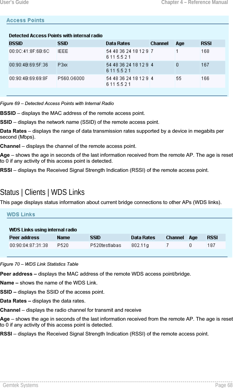
![User’s Guide Chapter 4 – Reference ManualFacility – indicates the unique identifier of the facility that generated the event. A facility can be a hardware device, a protocol, or a module of the system software.[Kernel/User/Security/Clock/LogAudit/LogAlert/System/Network/Wlan/management]ID – indicates an internal number for the event. Description – indicates description of the event. Count – indicates the number of times this event has occurred. Occurrence – indicates time when this event has occurred, in months, days andhours:minutes:seconds since the access point was started.Status | Clients | Wireless Clients All clients currently connected to the P-520r access point are listed in the Wireless Clients table. Select the Status | Clients | Wireless Clients menu if you want to get statistics regarding wirelessclients.The wireless clients are listed by their MAC address,Rate,Quality,RSSI,State and Ageparameters:Figure 68 – Connected Wireless Clients MAC Address – displays wireless client’s MAC address.Rate – displays the current data rate in Mbps.Quality – displays an indicator for the quality of the client (not supported yet). RSSI – displays the Received Signal Strength Indication (RSSI) in dBm of the client. State – displays the connection status between client and AP [Disconnected/ DiscAndUlPreauth/llAuthenticated/ llAuthAndUlPreauth/ Associated/ ulAuthenticated/ Key Distribution/Forwarding/Rejected]. Only clients in the state Forwarding will be able to send/receive data to/from other devices. Age – shows the age in seconds of the last information received from the client. The age is reset to 0 if any activity of this client is detected.Status | Clients | Access Points The page shows information about other wireless LANs in range. With this site survey administratorcan scan for neighboring access points; check their operating channels, view MAC addresses, Data rates, and other parameters. The site survey does not interrupt any client or WDS connection.Gemtek Systems Page 67](https://usermanual.wiki/GemTek-Technology/AP930301G.Manual/User-Guide-698765-Page-67.png)