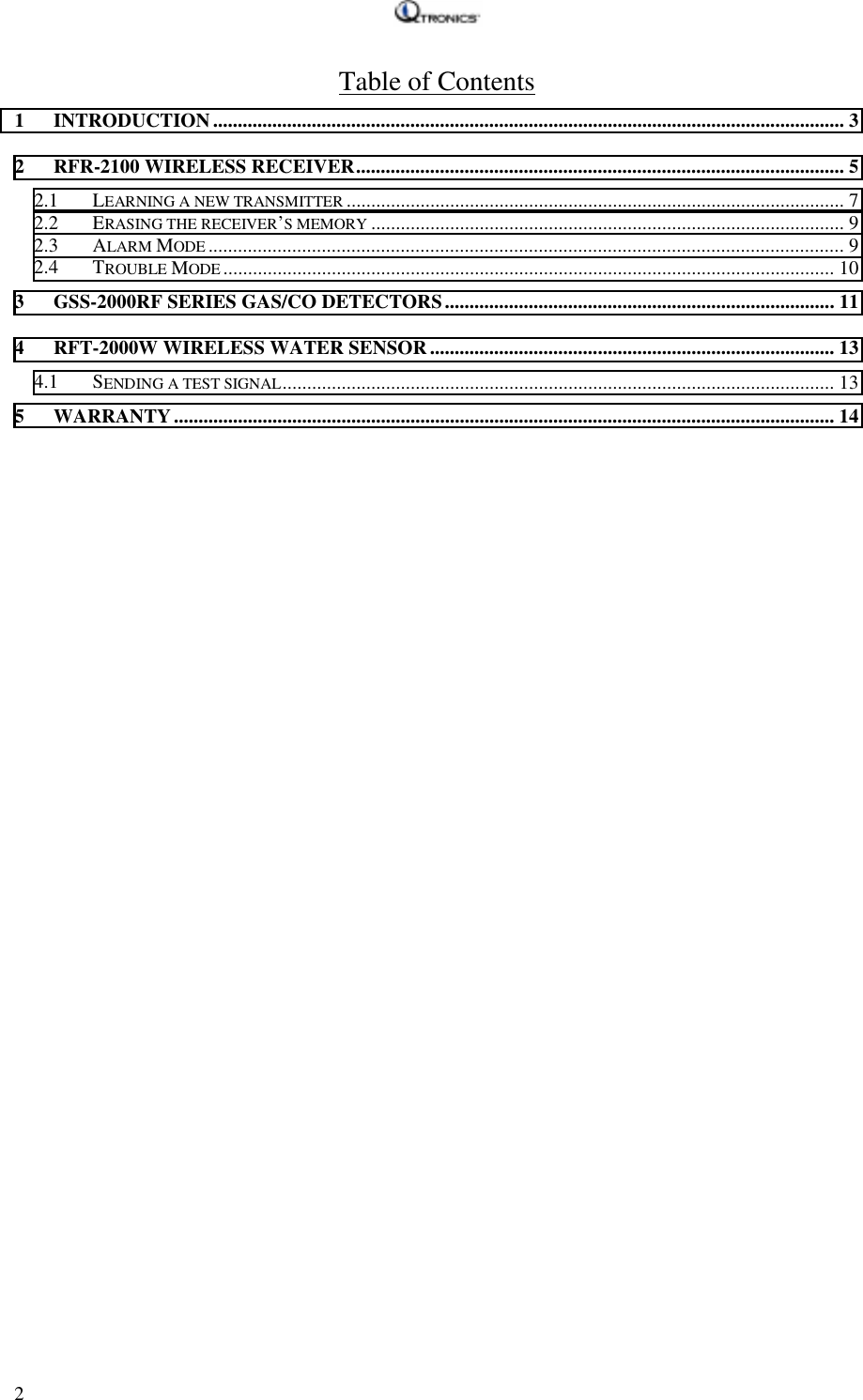
Gasguard Technologies RFT2001 Gas and water detector User Manual WR GG1201 Wireless Receiver Unit

Gasguard Technologies Inc. Gas and water detector WR GG1201 Wireless Receiver Unit

Manual

                     Maestro Wireless System User’s Guide
  2 Table of Contents 1 INTRODUCTION................................................................................................................................ 3 2  RFR-2100 WIRELESS RECEIVER................................................................................................... 5 2.1 LEARNING A NEW TRANSMITTER ..................................................................................................... 7 2.2 ERASING THE RECEIVER’S MEMORY ................................................................................................ 9 2.3 ALARM MODE ................................................................................................................................. 9 2.4 TROUBLE MODE ............................................................................................................................ 10 3  GSS-2000RF SERIES GAS/CO DETECTORS............................................................................... 11 4  RFT-2000W WIRELESS WATER SENSOR.................................................................................. 13 4.1 SENDING A TEST SIGNAL................................................................................................................ 13 5 WARRANTY...................................................................................................................................... 14
   3 Maestro Wireless System     operation manual   Congratulations on your purchase of the Maestro Wireless System.  Please read this manual carefully to familiarize yourself with its features and keep it on hand for future reference, especially the particular product you have purchased. (This manual covers the complete family of Maestro Wireless products).   1 Introduction  The Maestro Wireless System is a complete RF solution designed to work with both the Gas Maestro and Water Maestro systems simultaneously.  Its easy to use, requires minimal effort to set up, and with a range of up to 300ft it is an ideal alternative to running cables.  Like all Maestro systems, the Maestro Wireless System is modularized.  It can be used in combination with all other Maestro products.  This manual lists some of the more common products associated with the wireless system.  It should be noted that you are not limited to only those products listed in this manual when creating your system.  The Maestro Wireless System includes the following components: • RFR-2100 receiver • GSS-2000RF Series Gas/CO detector • RFT-2000W water detector (optional)* • RFV-960 valve controller.    * The Maestro Wireless System requires the use of at least one type of Maestro transmitter or any combination of Maestro transmitters.  The Maestro RFR-2100 wireless receiver is designed to operate with all the Maestro wireless transmitter(s).  Each RFR-2100 receiver can accept signals from up to 24 transmitters.  The receiver is the brain of the system.  It decodes the information sent from the transmitters and passes the signal on to any control devices attached to it (such as a GG960 Valve Controller)   With three different types of transmitters available, you have maximum flexibility in customizing a wireless solution to meet your needs.  The Maestro RFV-960 valve controller can be used as either gas valve controller or as a water valve controller.  When it receives a signal from the RFR-2100 receiver, it will automatically shut off the valve.  The reset button on the controller can be used to manually close the valve.  Once it is in alarm condition, it provides a normally open relay dry contact that can be used by a monitoring company.
  4   Main features built into the Maestro Wireless System are:  1. Easy to install:  Unlike most of the RF products' setup that requires customer to select channels and codes, the Maestro Wireless System is simply plug and play.   The receiver can automatically store the transmitter's unique ID.  No coding and channel selections are necessary.    2. Each transmitter is uniquely recognized:  Each Maestro RFT-2000 transmitter is guaranteed to be unique and will only be recognized by the specific receiver(s) which have been trained to work with that particular transmitter.  Wherever you install the Maestro Wireless System, there is no need to worry about possible interference from your neighbors.     3. Display clearly indicates individual zones:  The combinations of 8 zone LEDs and 3 page LEDs clearly display the 24 zones.  With this display, you can easily locate which transmitter is causing an alarm condition.    4. Can combine multiple systems into a single system:  The Maestro Wireless System is capable of operating as an independent system or as part of the Gas Maestro system or Water Maestro system.  It can also with operate with both systems simultaneously, combining the two separate systems into one complete system.  5. Compatible with existing products:  All Qtronics products are designed with standard input and output in mind.  Because of this standard, the Maestro Wireless System will work with most of our existing (and future) Maestro systems and Qtronics sensor products.
  52 RFR-2100 Wireless Receiver  The Maestro RFR-2100 receiver is the central hub of the system.  The base station is connected to the receiver through a four-wire telephone cable. This cable also supplies power to the receiver.    On the front plate of the RFR-2100 receiver, you will see: • 1 master LED • 8 zone LEDs, marked 1,2,3,4,5,6,7,8 • 3 page LEDs, marked I, II, III • 1 reset button   Figure 2.1:  RFR-2100 Wireless Receiver front panel  The receiver has 3 pages of memory (I, II, III), each of which has 8 zones (24 total) which can each store and recognize the unique ID of a single transmitter.    Page-Zone notation is used to represent each zone.  For example: • The first 2 zones are I-1 and I-2 • The final 2 zones are III-7 and III-8  The lit page LED displays which page is currently selected.  The lit zone LEDs on that page represent the zones that have been activated and are linked to transmitters.  Press the reset button to switch between pages.  Page I is reserved for transmitters with attached gas sensors (combustible or CO).  Pages II and III are reserved for transmitters with water sensors.  The receiver will
  6 automatically store transmitters on the correct page during the learning operation (see section 2.1 Learning a new transmitter).  The master LED indicates which function (mode) the unit is currently performing.   RFR-2100 receiver has the following 5 modes:  • Normal operation mode:    All the units at the remote stations (transmitter(s) and the connected sensors) are functioning normally.     All the units at the base station (valve controllers, valves, sensors) are functioning normally and the receiver is functioning properly.   While the receiver is in the normal operation mode, the master LED is steady green.  • Alarm mode:  The receiver received an alarm signal either from the one of the remote station(s) or from the base station.   The Master LED turns to red and the unit beeps.  If the alarm condition is received from a remote station, the LED indicating the zone of the station will flash on and off.  If the alarm condition is received from the base station, a page LED will flash on and off.  Page I indicates the alarm is from the gas system.   Page III indicates the alarm is from the water system.  • Trouble mode:  The valve is disconnected at the base station.   Page I LED flashing indicates a disconnected gas valve. Page III LED flashing indicates a disconnected water valve.  The Master LED turns to amber and the unit beeps.  • Learn mode:  The receiver is waiting for a new transmitter to transmit a signal.  After it receives the signal, the receiver stores this transmitter’s unique ID in its memory (see section 2.1 Learning a new transmitter).   The Master LED flashes red and green alternately while it is in learn mode.
  7 • Erase mode:  The receiver is about to erase its memory. Release the button to cancel.   Table 2.1:  Summary of the receiver's LED information LED  Status  Indication Off  Receiver is not powered Steady green  Normal operation Steady red  Alarm mode Flash green, red alternately  Learn mode Flash red   Erase mode Master LED Steady amber  Trouble mode Steady  Corresponding zone is normal Flashing  Corresponding zone is in alarm or in trouble Zone LED  Off Zone not activated One on at a time   Indicates the page the unit is displaying Page I flashing  Base station in Alarm or trouble mode caused by gas system. Page LED Page III flashing  Base station in alarm or trouble mode caused by water system   2.1 Learning a new transmitter  In order for the RFR-2100 receiver to receive a signal from a transmitter, the receiver must first store this transmitter’s unique ID into its memory.  The RFR-2100 receiver can store up to 24 transmitters into its memory.  When you first buy the unit, the unit’s memory is blank.  When a unit with the blank memory is powered up, there is no zone LED on.  Only the Master LED is on.   Six steps to learn a new transmitter:  Step 1:  Make sure the Receiver is off.  Step 2:  By pressing and holding the reset button of the RFR-2100 receiver during power up, the receiver will go into LEARN MODE.  The Master LED will flash red and
  8 green alternatively when the unit is in LEARN MODE.  The unit will stay in LEARN MODE until it receives a new transmitter ID.  Step 3:  Send a test signal from the transmitter you want the receiver to learn. (See sections 3 & 4 on how to transmit a test signal).  Step 4:  The receiver receives a test signal and stores the ID number in its memory.  A zone LED is lit up showing this zone is activated.  The receiver returns to normal operation mode.  Step 5:  To confirm that communication has been established, you can: • Send a test signal from the transmitter see if the receiver goes into alarm mode. • Send a reset signal from transmitter see if the receiver returns to normal mode (RFT-2000B and RFT-2000G only).  Repeat this step a couple of times. It helps you to determine whether a good signal reception has been established.     This procedure is also used to perform a manual check of the system.  Step 6:  After you make sure communication is good, label the transmitter.  The label should have the page number (I, II, III) and zone number (1~8) on it.  The unit learns one transmitter at a time and will store that transmitter’s ID in the first available zone.  The first gas sensor will be stored in page I, zone 1 (I-1).  The first water sensor will be stored in page III, zone 1.  When page III is full, the next water sensor will be stored in page II, zone 1 (II-1)  If you want to learn more transmitters, repeat steps 1 to 6 for each transmitter.  If the transmitter has both gas and water sensors attached, the receiver will need to complete this procedure twice: once using a gas test signal and once using a water test signal.  This will cause the transmitter’s ID to be stored on both the gas page (page I) and the water page (page II or III).  With this setup, you can easily determine whether a signal from a transmitter is caused by an attached water sensor or by an attached gas sensor.
  92.2 Erasing the receiver’s memory  The receiver’s memory can be erased one page at a time, or any combination of pages at once.  It cannot erase individual zones.  To erase the memory on the receiver, follow this procedure:  1) Press and hold the reset button until the unit beeps rapidly and the master LED flashes amber and green alternatively (approximately 10 seconds). 2) Release the button and wait until the unit beeps rapidly again and the master LED rapidly flashes red (approximately 10 seconds). 3) The receiver is now in Erase Mode.  Press the button until the page(s) you want to delete are lit. 4) When the unit starts to beep rapidly again, press the button once to confirm deletion.  You will hear one long beep for each page being erased.  To cancel this procedure, release the button and wait until the receiver returns to normal operation mode.  2.3 Alarm Mode  After the receiver enters alarm mode:  1) Confirm the alarm condition:  The receiver’s master LED is red and the unit is beeping.   2) Locate the problem:  If either the page I LED or the page III LED are flashing, it means the problem comes from the base station.  Page I indicates a gas system alarm. Page III indicates a water system alarm.  Check which zone LED is flashing.  This is the zone causes the problem.  Switch the pages, there are may be more than one zone in alarm mode.  3) Check the base station:  If the problem is caused by the base station, the M-960 valve controller and the sensor should remain in alarm mode. The gas valve is closed if the gas sensor goes into alarm.  The water valve is closed if the water sensor goes into alarm.     4) Check the remote station:  If problem caused by remote station, check the remote station.  If an alarm condition is still present, both transmitter and the connecting sensor(s)
  10 should stay in alarm mode.  5) Reset the receiver:  After all the transmitters in alarm condition have been reset, you can press the reset button, reset the unit back to its normal operation mode.  You cannot reset the receiver if any transmitter is still in alarm mode.  2.4 Trouble Mode  After a receiver enters trouble mode:   1) Locate the problem:  If either the page I LED or the page III LED is flashing, it means the problem comes from the base station.  Page I indicates a gas valve problem. Page III indicates a water valve problem.  2) Check the valve connection and jumper wire on valve controller (see section 5)  3) You can reset the receiver from trouble mode back to normal operation mode.    Specifications:    Encoding: Pulse width modulation    Frequency: 433MHz    Power input:  12VDC+15%       Supplied from M-960 valve controller.       Current consumption (12VDC):  30mA    Temperature:  0~49°C (32F~120F)    Humidity:  20%-90%       Cable length: 50 meters (150ft) max     The Maestro Wireless System is very reliable and is tested to high standards.  This device complies with Part 15 of the FCC rules.  Operation is subject to the following two conditions: (1) This device may not cause harmful interference, and (2) this device must accept any interference including interference that may cause undesired operation.  Any changes or modifications made to this device without express written approval from Qtronics Manufacturing Inc. could void the end user’s authority to operate this device under FCC regulations.
  113 GSS-2000RF Series Gas/CO Detectors Available models: • GSS-2001RF Gas and Carbon Monoxide Detector • GSS-2002RF Carbon Monoxide Detector • GSS-2003RF Gas Detector Figure 3.1:  RFT-2000 front panel    To send a test signal for gas systems: Press and hold the button for 5 seconds.  The unit transmits a test signal  After sending a test signal, press and release the button again, the transmitter transmits a reset signal.  To send a test signal for water systems: Make sure the water sensor is connected to the transmitter. Gently touch and release the probes on the water sensor with moist fingertips or lightly dip the sensor’s probes into a cup of water.
  12   Specifications:     Encoding: Pulse width modulation     Frequency: 433MHz    Power input:  12VDC+15% Supplied from 12VDC wall adapter, Current consumption: Stand by: 4mA Transmit: 14mA    Temperature:  0~49°C (32F~120F)     Humidity:  20%-90%     Transmission length: 2 seconds   The Maestro Wireless System is very reliable and is tested to high standards.  This device complies with Part 15 of the FCC rules.  Operation is subject to the following two conditions: (1) This device may not cause harmful interference, and (2) this device must accept any interference including interference that may cause undesired operation.  Any changes or modifications made to this device without express written approval from Qtronics Manufacturing Inc. could void the end user’s authority to operate this device under FCC regulations.
  134 RFT-2000W Wireless Water Sensor  The RFT-2000W wireless water sensor is powered by a lithium battery (included).  Since this unit consumes very little power, the battery will last at least 5 years under normal conditions.  To preserve battery life, the battery is disconnected after testing at the factory.  To reconnect the battery, pull the disposable pull-tab.  Verify that the unit is activated by pushing the button.  If the LED lights, the unit is activated and ready for use.  At the bottom of the unit, there are two test probes.  These probes are used to detect potential water presence.  When water is present at the test probes, the unit goes into alarm mode.  The LED on the unit turns red.  Figure 4.1: RFT-2000W Wireless Water Sensor4.1 Sending a test signal  The RFT-2000W transmitter can send two types of test signals: • A simple test signal − A signal is sent to the receiver without causing an alarm condition. − To send a test signal press the button and release within 5 seconds.  • A simulated alarm condition − A signal is sent to the receiver, which causes an alarm condition and causes the valve to close. − To send a simulated alarm condition, press and hold the button for at least 5 seconds.  Specifications:    Encoding: Pulse width modulation    Frequency: 433MHz       Power input:  3V  Supplied from included battery,    Temperature:  0~49°C (32F~120F)    Humidity:  20%-90%    Transmission length: 2 seconds   The Maestro Wireless System is very reliable and is tested to high standards.  This device complies with Part 15 of the FCC rules.  Operation is subject to the following two conditions: (1) This device may not cause harmful interference, and (2) this device must accept any interference including interference that may cause undesired operation.  Any changes or modifications made to this device without express written approval from Qtronics Manufacturing, Inc. could void the end user’s authority to operate this device under FCC regulations.
  14 5 Warranty     Limited Warranty  Qtronics warrants to the original purchaser that this product will be free from defects in material and workmanship under normal residential use and services for a period of five (5) years from the date of purchase. Qtronics’ liability is limited to the replacement of the product provided that proof of purchase date is presented to Qtronics Manufacturing Inc. This warranty is void if the product has been damaged by accident, tampering, misuse, abuse, lack of reasonable care for the product or used in applications not in accordance with this User’s Guide. This warranty is in lieu of all other express warranties, obligations or liabilities. Qtronics shall have no liability for any personal injury, property damage or any special incidental, contingent or consequential damage of any kind resulting from gas leakage, fire or explosion.

Navigation menu