Gantner Electronic GEA1160018A GAT NET.Writer 7000 F/ISO User Manual GAT NET Writer 7000 F ISO
Gantner Electronic GmbH GAT NET.Writer 7000 F/ISO GAT NET Writer 7000 F ISO
UserManual.wiki
>
Gantner Electronic
>
GEA1160018A User Manual
Manual
Navigation menu
Upload a User Manual
Namespaces
Wiki Guide
HTML
PDF
Info
Views
User Manual
Discussion / Help
Navigation

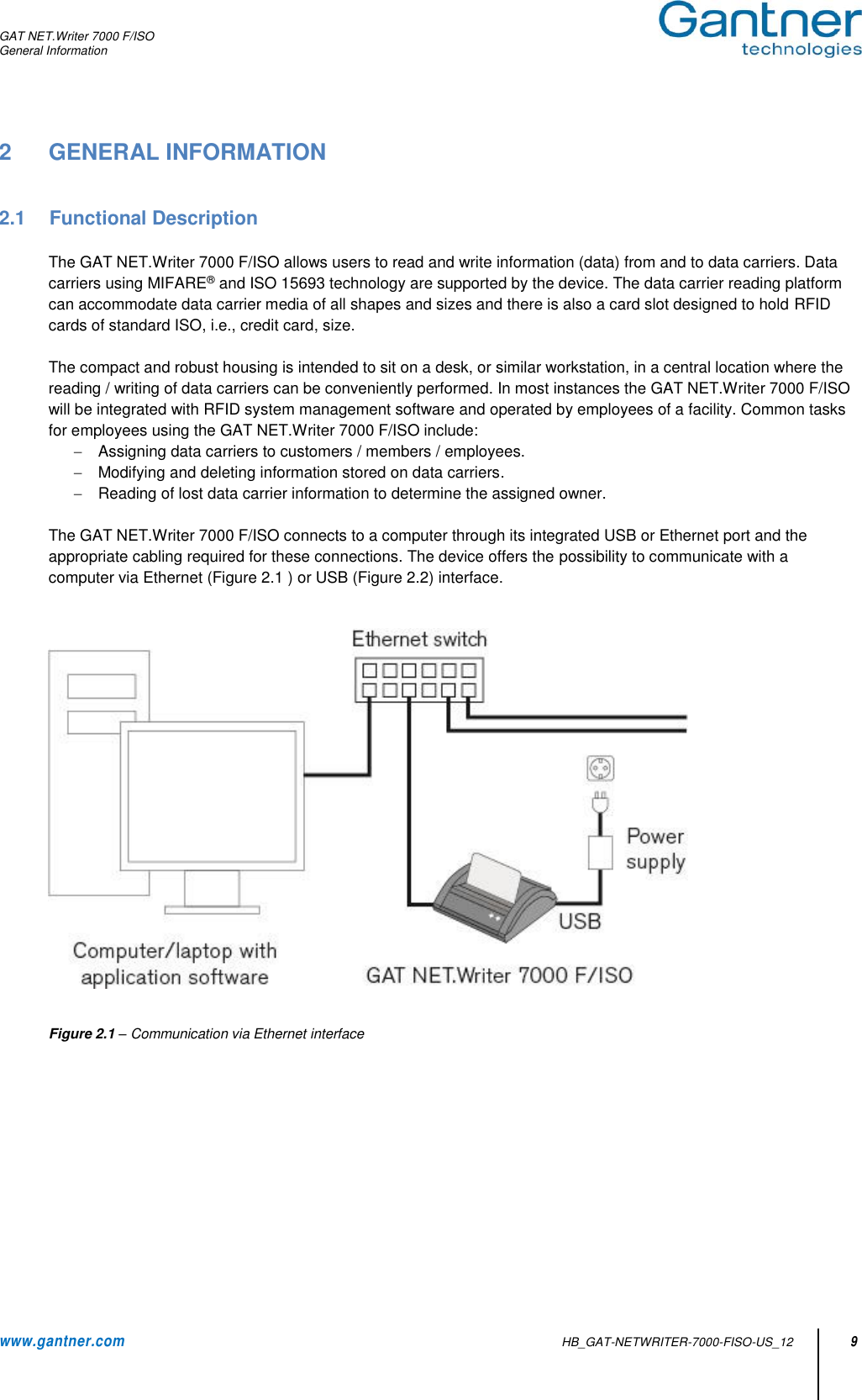
![GAT NET.Writer 7000 F/ISO 4 HB_GAT-NETWRITER-7000-FISO-US_12 www.gantner.com General Warning and Safety Instructions Dear Customer, We congratulate you on selecting a product (appliance or software) from GANTNER Electronic GmbH. Our aim is to ensure our product operates with safety and to your complete satisfaction. To achieve this aim, please take this opportunity to familiarize yourself with the following guidelines: 1. The installation, commissioning, operation, and maintenance of the product must be carried out in accordance with the technical conditions of operation as described in the corresponding product documentation. 2. Before installing, commissioning, operating, or maintaining the product, it is essential to read the corresponding chapter of this manual and observe the instructions and information therein. 3. If there are some points which are not entirely clear, please do not take a chance. All queries can be clarified by your GANTNER representative or by ringing the GANTNER support hotline. 4. Where not otherwise specifically documented, the appropriate installation, commissioning, operation and maintenance of the product is the customer’s responsibility. 5. Directly on receipt of the goods, inspect both the packaging and the product itself for any signs of damage. Also check that the delivery is complete and includes all accessories, documentation, auxiliary devices, etc. 6. If the packaging or product has been damaged in transport, or should you suspect that it may have a fault, the product must not be put into service. Contact your GANTNER representative who will resolve the problem as quickly as possible. 7. The installation, commissioning, and servicing of our products must be performed by suitably trained personnel. In particular, electrical connections must only be made by correspondingly qualified specialists. Always observe the relevant installation regulations in accordance with the national Electrical Engineers Association (e.g., ÖVE [Austrian], VDE [Germany]). 8. Where not otherwise stated, installation and maintenance work on our products must be carried out when disconnected from the power supply. This applies in particular to appliances that are normally supplied by low-voltage current. 9. It is prohibited to alter the products or remove protective shields and covers. 10. Do not attempt to repair a product after a defect, failure, or damage is detected. In addition, do not put the product back into operation. In such cases, it is essential to contact your GANTNER representative or the GANTNER support hotline. 11. GANTNER Electronic GmbH accepts no responsibility for any injuries or damage caused as a result of improper use. 12. Although care is taken and we are continuously aiming for improvement, we cannot completely exclude the possibility of errors appearing in our documentation. GANTNER Electronic GmbH therefore accepts no responsibility for the completeness or the accuracy of this manual. The right is reserved to make alterations at any time without prior notice. 13. Should you discover any fault with the product or in its accompanying documentation, or you have any suggestions for improvement, you may confidently inform your GANTNER representative or GANTNER Electronic GmbH directly. 14. We especially look forward to hearing from you if you just want to tell us that everything is functioning perfectly. We wish you a successful experience with our product and look forward to welcoming you again as a customer soon.](https://usermanual.wiki/Gantner-Electronic/GEA1160018A/User-Guide-3295857-Page-4.png)

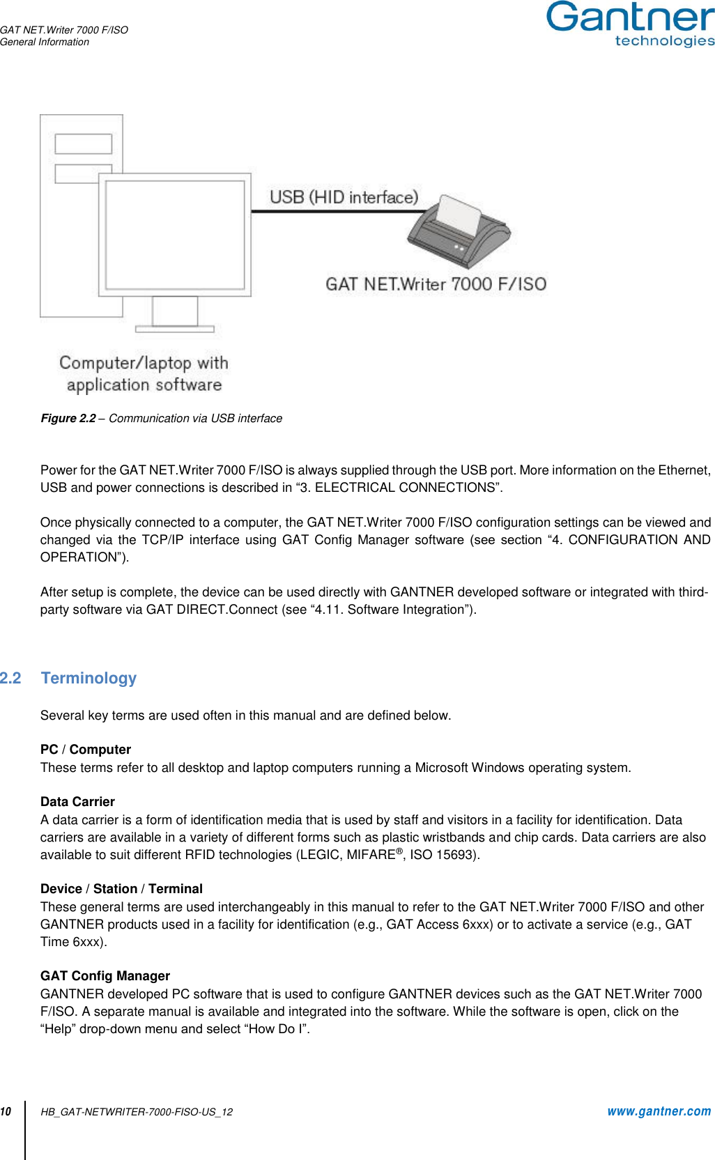
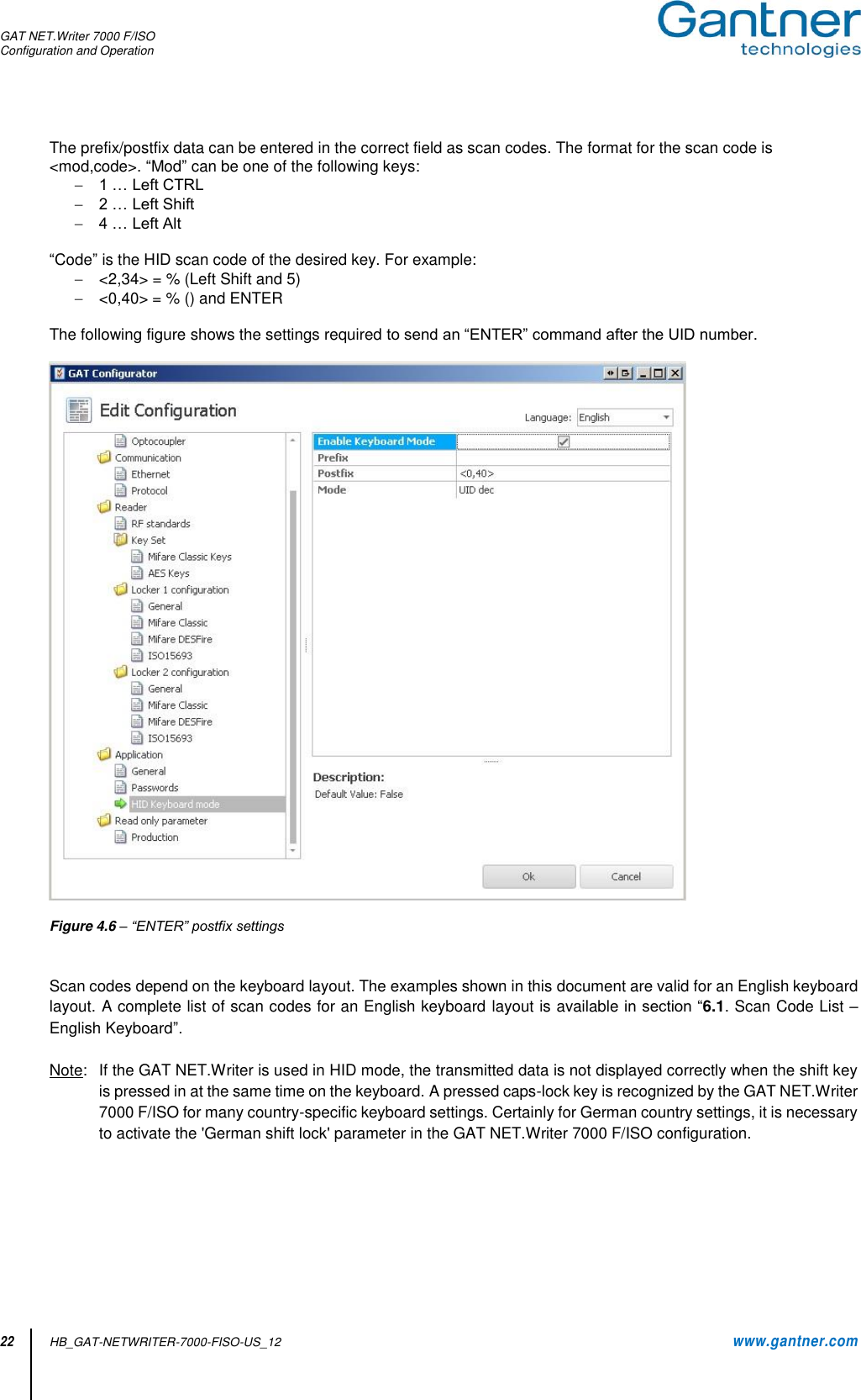

![GAT NET.Writer 7000 F/ISO Appendix www.gantner.com HB_GAT-NETWRITER-7000-FISO-US_12 31 6 APPENDIX 6.1 Scan Code List – English Keyboard 0x00 Reserved (no event indicated) 0x30 Keyboard ] and } 0x01 0x01 Keyboard ErrorRollOver 0x31 Keyboard \ and | 0x02 Keyboard POSTFail 0x32 Keyboard Non-US # and ~ 0x03 Keyboard ErrorUndefined 0x33 Keyboard ; and : 0x04 Keyboard a and A 0x34 Keyboard ' and " 0x05 Keyboard b and B 0x35 Keyboard Grave Accent and Tilde 0x06 Keyboard c and C 0x36 Keyboard, and < 0x07 Keyboard d and D 0x37 Keyboard . and > 0x08 Keyboard e and E 0x38 Keyboard / and ? 0x09 Keyboard f and F 0x39 Keyboard Caps Lock 0x0A Keyboard g and G 0x3A Keyboard F1 0x0B Keyboard h and H 0x3B Keyboard F2 0x0C Keyboard i and I 0x3C Keyboard F3 0x0D Keyboard j and J 0x3D Keyboard F4 0x0E Keyboard k and K 0x3E Keyboard F5 0x0F Keyboard l and L 0x3F Keyboard F6 0x10 Keyboard m and M 0x40 Keyboard F7 0x11 Keyboard n and N 0x41 Keyboard F8 0x12 Keyboard o and O 0x42 Keyboard F9 0x13 Keyboard p and P 0x43 Keyboard F10 0x14 Keyboard q and Q 0x44 Keyboard F11 0x15 Keyboard r and R 0x45 Keyboard F12 0x16 Keyboard s and S 0x46 Keyboard PrintScreen 0x17 Keyboard t and T 0x47 Keyboard Scroll Lock 0x18 Keyboard u and U 0x48 Keyboard Pause 0x19 Keyboard v and V 0x49 Keyboard Insert 0x1A Keyboard w and W 0x4A Keyboard Home 0x1B Keyboard x and X 0x4B Keyboard PageUp 0x1C Keyboard y and Y 0x4C Keyboard Delete Forward 0x1D Keyboard z and Z 0x4D Keyboard End 0x1E Keyboard 1 and ! 0x4E Keyboard PageDown 0x1F Keyboard 2 and @ 0x4F Keyboard RightArrow 0x20 Keyboard 3 and # 0x50 Keyboard LeftArrow 0x21 Keyboard 4 and $ 0x51 Keyboard DownArrow 0x22 Keyboard 5 and % 0x52 Keyboard UpArrow 0x23 Keyboard 6 and ^ 0x53 Keypad Num Lock and Clear 0x24 Keyboard 7 and & 0x54 Keypad / 0x25 Keyboard 7 and & 0x55 Keypad * 0x26 Keyboard 9 and ( 0x56 Keypad - 0x27 Keyboard 0 and ) 0x57 Keypad + 0x28 Keyboard Return (ENTER) 0x58 Keypad ENTER 0x29 Keyboard ESCAPE 0x59 Keypad 1 and End 0x2A Keyboard DELETE (Backspace) 0x5A Keypad 2 and Down Arrow 0x2B Keyboard Tab 0x5B Keypad 3 and PageDn 0x2C Keyboard Spacebar 0x5C Keypad 4 and Left Arrow 0x2D Keyboard - and (underscore) 0x5D Keypad 5 0x2E Keyboard = and + 0x5E Keypad 6 and Right Arrow 0x2F Keyboard [ and { 0x5F Keypad 7 and Home 0x60 Keypad 8 and Up Arrow 0x7D Keyboard Paste 0x61 Keypad 9 and PageUp 0x7E Keyboard Find 0x62 Keypad 0 and Insert 0x7F Keyboard Mute 0x63 Keypad . and Delete 0x80 Keyboard Volume Up 0x64 Keyboard Non-US \ and | 0x81 Keyboard Volume Down 0x65 Keyboard Application 0x82 Keyboard Locking Caps Lock 0x66 Keyboard Power 0x83 Keyboard Locking Num Lock 0x67 Keypad = 0x84 Keyboard Locking Scroll Lock 0x68 Keyboard F13 0x85 Keypad Comma 0x69 Keyboard F14 0x86 Keypad Equal Sign 0x6A Keyboard F15 0x87 Keyboard International1 0x6B Keyboard F16 0x88 Keyboard International2](https://usermanual.wiki/Gantner-Electronic/GEA1160018A/User-Guide-3295857-Page-31.png)
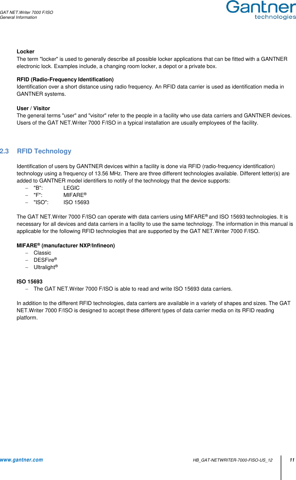
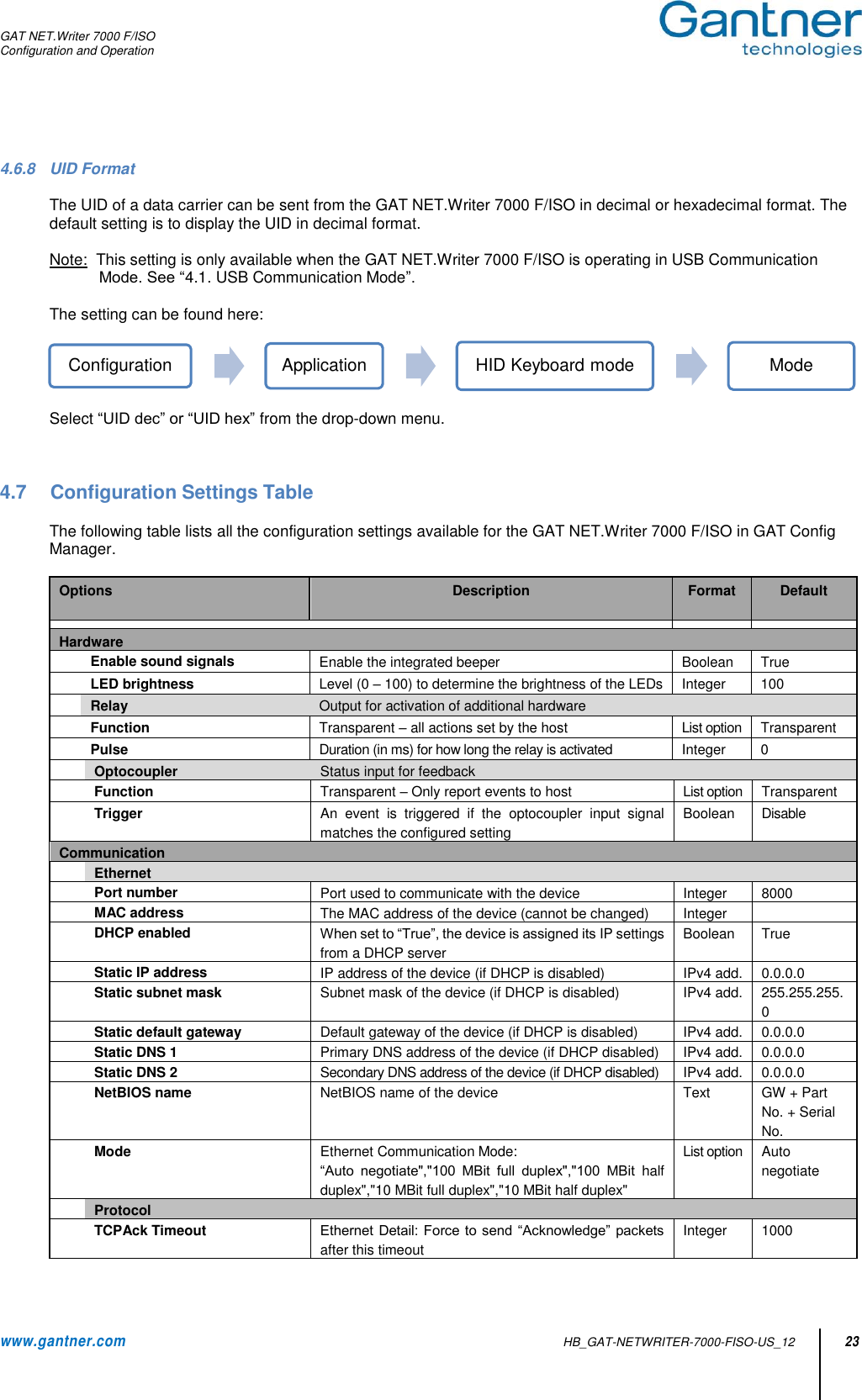
![GAT NET.Writer 7000 F/ISO Appendix 32 HB_GAT-NETWRITER-7000-FISO-US_12 www.gantner.com 0x6C Keyboard F17 0x89 Keyboard International3 0x6D Keyboard F18 0x8A Keyboard International4 0x6E Keyboard F19 0x8B Keyboard International5 0x6F Keyboard F20 0x8C Keyboard International6 0x70 Keyboard F21 0x8D Keyboard International7 0x71 Keyboard F22 0x8E Keyboard International8 0x72 Keyboard F23 0x8F Keyboard International9 0x73 Keyboard F24 0x90 Keyboard LANG1 0x74 Keyboard Execute 0x91 Keyboard LANG2 0x75 Keyboard Help 0x92 Keyboard LANG3 0x76 Keyboard Menu 0x93 Keyboard LANG4 0x77 Keyboard Select 0x94 Keyboard LANG5 0x78 Keyboard Stop 0x95 Keyboard LANG6 0x79 Keyboard Again 0x96 Keyboard LANG7 0x7A Keyboard Undo 0x97 Keyboard LANG8 0x7B Keyboard Cut 0x98 Keyboard LANG9 0x7C Keyboard Copy FCC INFORMATION (U.S.A.) Note: This equipment has been tested and found to comply with the limits for a Class B digital device, pursuant to part 15 of the FCC Rules. These limits are designed to provide reasonable protection against harmful interference in a residential installation. This equipment generates, uses, and can radiate radio frequency energy and, if not installed and used in accordance with the instructions, may cause harmful interference to radio communications. However, there is no guarantee that interference will not occur in a particular installation. If this equipment does cause harmful interference to radio or television reception, which can be determined by turning the equipment off and on, the user is encouraged to try to correct the interference by one or more of the following measures: - Reorient or relocate the receiving antenna. - Increase the separation between the equipment and receiver. - Connect the equipment into an outlet on a circuit different from that of which the receiver is connected. - Consult the dealer or an experienced radio/TV technician for help. FCC Warning Statement [Any] changes or modifications not expressly approved by the party responsible for compliance could void the user's authority to operate the equipment. (CANADA) This device complies with Industry Canada’s licence-exempt RSSs. Operation is subject to the following two conditions: (1) This device may not cause interference; and (2) This device must accept any interference, including interference that may cause undesired operation of the device. Le présent appareil est conforme aux CNR d’Industrie Canada applicables aux appareils radio exempts de licence. L’exploitation est autorisée aux deux conditions suivantes : 1) l’appareil ne doit pas produire de brouillage; 2) l’appareil doit accepter tout brouillage radioélectrique subi, même si le brouillage est susceptible d’en compromettre le onctionnement. Note: This manual is valid from February 16th, 2017. It is subject to change. Amendments can be made without prior notice at any time.](https://usermanual.wiki/Gantner-Electronic/GEA1160018A/User-Guide-3295857-Page-32.png)