Gantner Electronic GEA1150001A Electronic RFID Locker Locks User Manual GAT NET Lock 7000
Gantner Electronic GmbH Electronic RFID Locker Locks GAT NET Lock 7000
UserManual.wiki
>
Gantner Electronic
>
GEA1150001A User Manual
Users manual
Navigation menu
Upload a User Manual
Namespaces
Wiki Guide
HTML
PDF
Info
Views
User Manual
Discussion / Help
Navigation
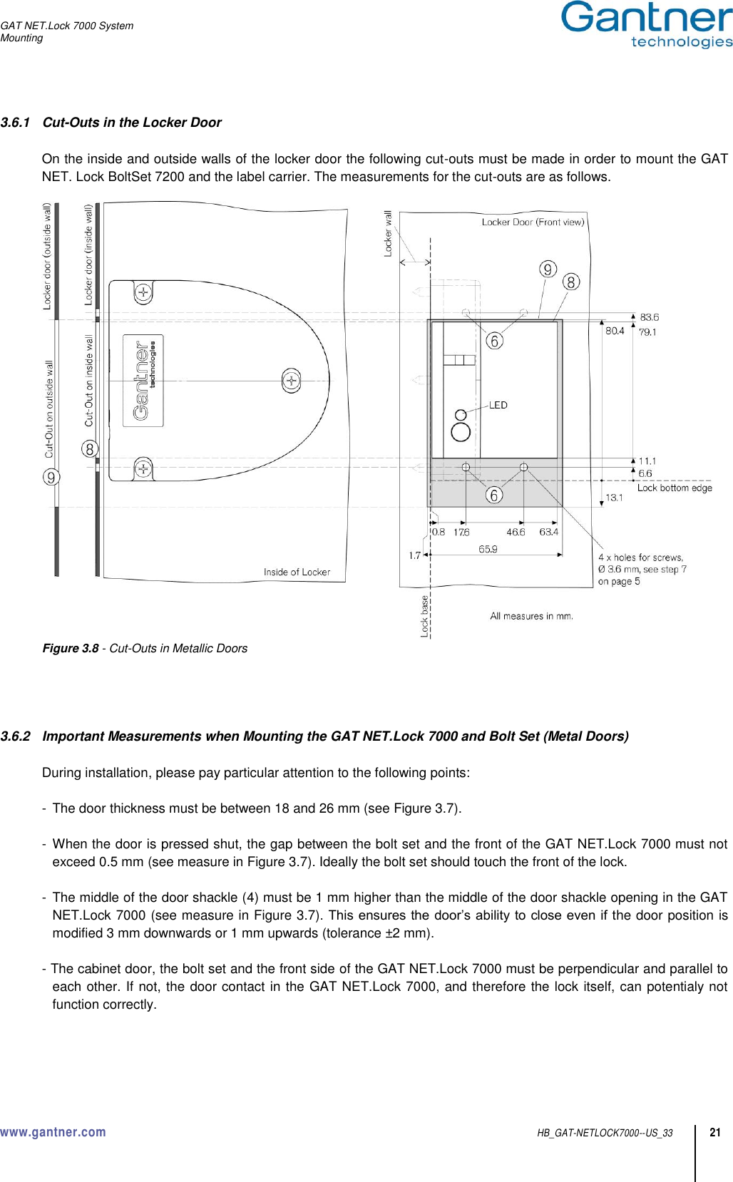
![GAT NET.Lock 7000 System www.gantner.com HB_GAT-NETLOCK7000--US_33 3 Copyright 2014-2015, GANTNER Electronic GmbH, Schruns (Austria). General warning and safety instructions Dear customer, We congratulate you on having selected a product (appliance or software) from GANTNER Electronic GmbH. Our aim is to ensure that our product operates with safety and to your complete satisfaction. To achieve this aim we take this opportunity to familiarise you with the following guidelines: 1. Installation, commissioning, operation and maintenance of the purchased product must be carried out in accordance with the instructions, i.e., in accordance with the technical conditions of operation as described in the corresponding product documen-tation. 2. Before installation, commissioning, operation or maintenance it is therefore essential that you read the corresponding chapter of this manual and observe its instructions. 3. If there are still some points on which you are not entirely clear, please do not take a chance. All queries can be clarified by your Gantner company representative, or by ringing the GANTNER Electronic GmbH hotline. 4. Where not otherwise specifically documented, the appropriate installation, commissioning, operation and maintenance of the product is the customer’s responsibility. 5. Directly on receipt of the goods, inspect both the packaging and the product itself for any signs of damage. Also check that the delivery is complete and includes all accessories, documentation, auxiliary devices, etc. 6. If the packaging or product has been damaged in transport, or should you suspect that it may have a fault, the product must not be put into service. In this case, contact your Gantner company representative. They will make every effort to resolve the problem as quickly as possible. 7. Installation, commissioning and servicing of our appliances must only be carried out by suitably trained personnel. In particu-lar, electrical connections must only be made by correspondingly qualified specialists. Here, the appropriate installation provi-sions in accordance with the relevant national Electrical Engineers construction regulations (e.g., ÖVE, [Austrian] VDE, [Ger-man]...) must be observed. 8. Where not otherwise stated, installation and maintenance work on our appliances must be carried out when disconnected from the power supply. This applies in particular to appliances which are normally supplied by low-voltage current. 9. It is prohibited to make alterations to the appliances or to remove protective shields and covers. 10. Do not attempt yourself to repair an appliance after a defect, failure or damage, or to put it back into operation again. In such cases, it is essential you contact either your Gantner company representative or the GANTNER Electronic GmbH hotline. 11. GANTNER Electronic GmbH accepts no responsibility for any injuries or damage caused as a result of improper use. 12. Although every care is taken and we are continuously aiming for improvement, we cannot completely exclude the possibility of errors appearing in our documentation. GANTNER Electronic GmbH therefore accepts no responsibility for the complete-ness or the accuracy of this manual. The right is reserved to make alterations, and we may carry out alterations at any time without giving prior notice. 13. Should you discover any fault with the product or in its accompanying documentation, or have any suggestions for improve-ment, you may confidently approach either your Gantner company representative or GANTNER Electronic GmbH directly. !](https://usermanual.wiki/Gantner-Electronic/GEA1150001A/User-Guide-2627498-Page-3.png)
![GAT NET.Lock 7000 System Technical Data www.gantner.com HB_GAT-NETLOCK7000--US_33 43 FCC INFORMATION (U.S.A.) GAT NET.Controller S 7000 F/ISO Note: This device complies with Part 15 of the FCC Rules. Operation is subject to the following two conditions: (1) this device may not cause harmful interference, and (2) this device must accept any interference received, including interference that may cause undesired operation. GAT NET.Controller M 7000 F/ISO and GAT NET.Lock 7000 Note: This equipment has been tested and found to comply with the limits for a Class B digital device, pursuant to part 15 of the FCC Rules. These limits are designed to provide reasonable protection against harmful inter-ference in a residential installation. This equipment generates, uses, and can radiate radio frequency energy and, if not installed and used in accordance with the instructions, may cause harmful interference to radio communications. However, there is no guarantee that interference will not occur in a particular installation. If this equipment does cause harmful interference to radio or television reception, which can be determined by turning the equipment off and on, the user is encouraged to try to correct the interference by one or more of the following measures: - Reorient or relocate the receiving antenna. - Increase the separation between the equipment and receiver. - Connect the equipment into an outlet on a circuit different from that of which the receiver is connected. - Consult the dealer or an experienced radio/TV technician for help. FCC Warning Statement [Any] changes or modifications not expressly approved by the party responsible for compliance could void the user's authority to operate the equipment. This WEEE symbol on the products or on their packaging indicates that the corresponding product must not be disposed of with normal household waste. Instead such marked waste equipment must be disposed of by handing it over to a designated collection point for the recycling of waste electrical and electronic equip-ment. By separating and recycling this waste equipment at the time of disposal will help to conserve natural re-sources and ensure that it is recycled in a manner that protects human health and the environment. Please contact your local authority for further details of your nearest designated collection point. _ _ Note: This manual is valid as from March 24th 2015. It is subject to change and amendments and changes can be made without prior notice at anytime!](https://usermanual.wiki/Gantner-Electronic/GEA1150001A/User-Guide-2627498-Page-43.png)