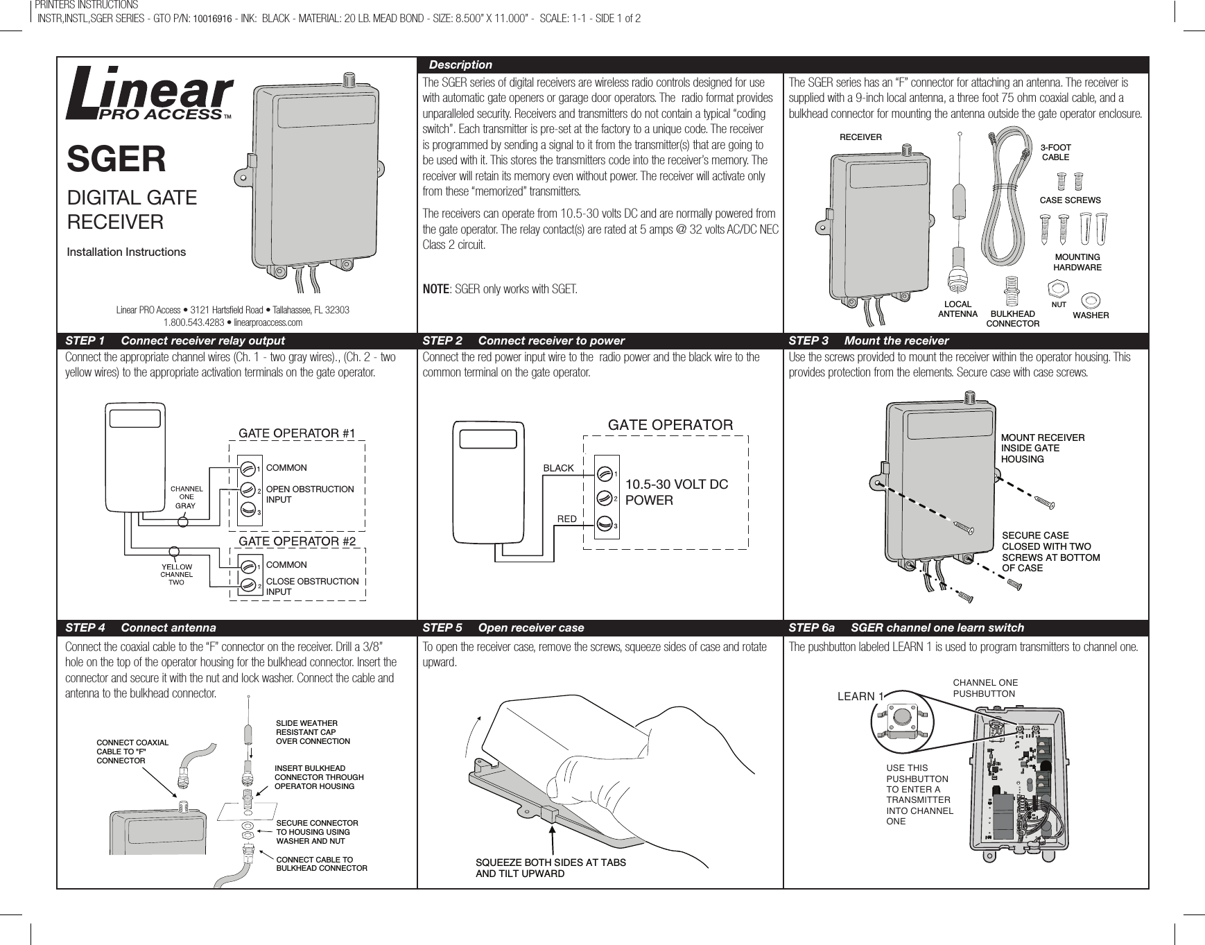
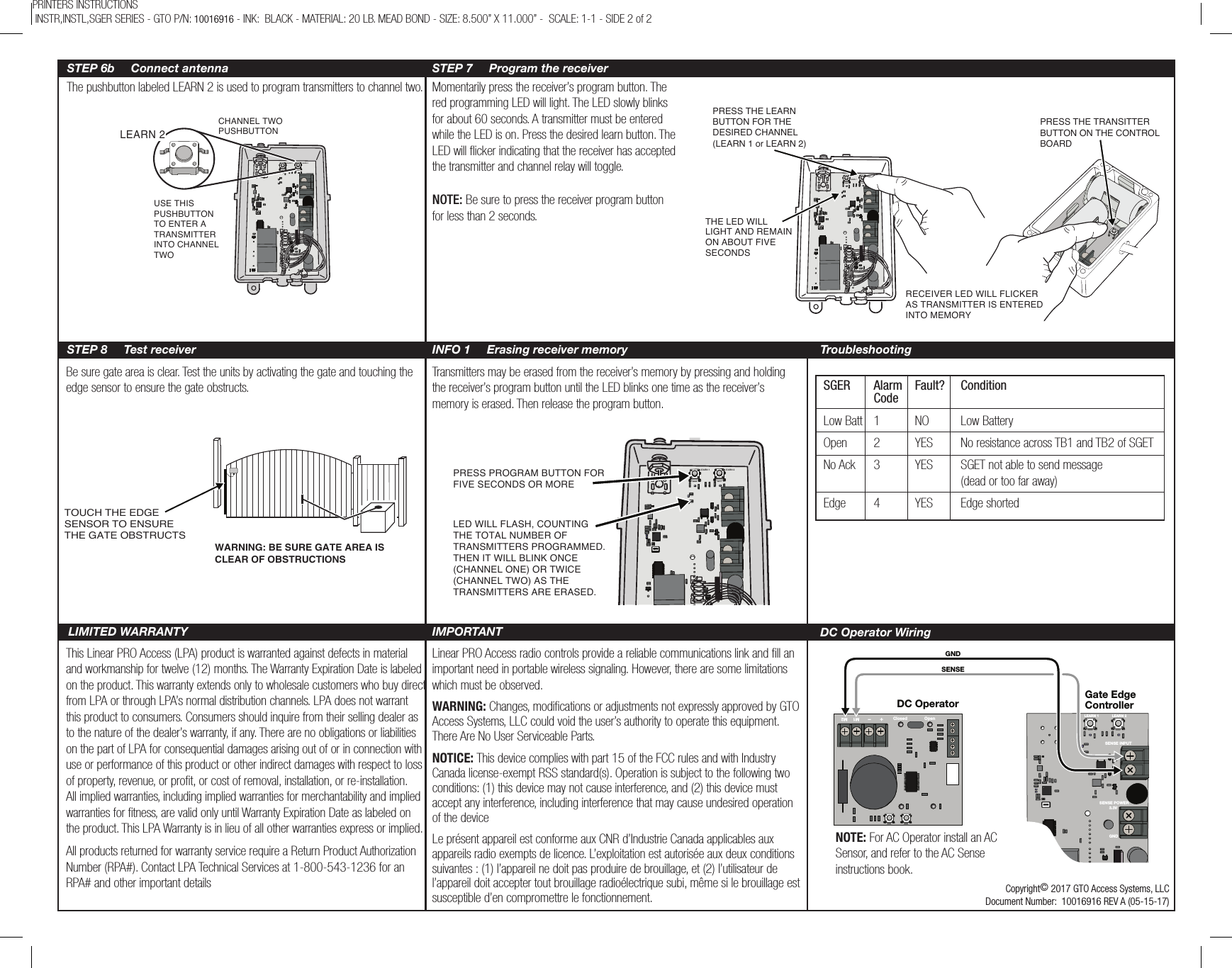
GTO Access Systems SGER GATE EDGE CONTROL UNIT User Manual

GTO Access Systems, LLC GATE EDGE CONTROL UNIT

User Manual

The SGER series of digital receivers are wireless radio controls designed for use with automatic gate openers or garage door operators. The  radio format provides unparalleled security. Receivers and transmitters do not contain a typical “coding switch”. Each transmitter is pre-set at the factory to a unique code. The receiver is programmed by sending a signal to it from the transmitter(s) that are going to be used with it. This stores the transmitters code into the receiver’s memory. The receiver will retain its memory even without power. The receiver will activate only from these “memorized” transmitters.The receivers can operate from 10.5-30 volts DC and are normally powered from the gate operator. The relay contact(s) are rated at 5 amps @ 32 volts AC/DC NEC Class 2 circuit.NOTE: SGER only works with SGET.The SGER series has an “F” connector for attaching an antenna. The receiver is supplied with a 9-inch local antenna, a three foot 75 ohm coaxial cable, and a bulkhead connector for mounting the antenna outside the gate operator enclosure.Connect the appropriate channel wires (Ch. 1 - two gray wires)., (Ch. 2 - two yellow wires) to the appropriate activation terminals on the gate operator.Connect the red power input wire to the  radio power and the black wire to the common terminal on the gate operator.Use the screws provided to mount the receiver within the operator housing. This provides protection from the elements. Secure case with case screws.Connect the coaxial cable to the “F” connector on the receiver. Drill a 3/8” hole on the top of the operator housing for the bulkhead connector. Insert the connector and secure it with the nut and lock washer. Connect the cable and antenna to the bulkhead connector.To open the receiver case, remove the screws, squeeze sides of case and rotate upward.The pushbutton labeled LEARN 1 is used to program transmitters to channel one.PRINTERS INSTRUCTIONS  INSTR,INSTL,SGER SERIES - GTO P/N: 10016916 - INK:  BLACK - MATERIAL: 20 LB. MEAD BOND - SIZE: 8.500” X 11.000” -  SCALE: 1-1 - SIDE 1 of 2RECEIVERLOCAL ANTENNA BULKHEADCONNECTOR3-FOOT CABLECASE SCREWSMOUNTING HARDWAREWASHERNUTCOMMONOPEN OBSTRUCTIONINPUTCOMMONCLOSE OBSTRUCTIONINPUT10.5-30 VOLT DCPOWERMOUNT RECEIVERINSIDE GATE  HOUSINGSECURE CASE CLOSED WITH TWO SCREWS AT BOTTOMOF CASECONNECT COAXIAL CABLE TO "F" CONNECTORSLIDE WEATHERRESISTANT CAPOVER CONNECTIONINSERT BULKHEADCONNECTOR THROUGHOPERATOR HOUSINGSECURE CONNECTOR TO HOUSING USING WASHER AND NUTCONNECT CABLE TOBULKHEAD CONNECTORSQUEEZE BOTH SIDES AT TABSAND TILT UPWARDSGERDIGITAL GATE RECEIVERInstallation InstructionsPRO ACCESSTMDescriptionSTEP 1     Connect receiver relay output STEP 2     Connect receiver to power STEP 3     Mount the receiverSTEP 4     Connect antenna STEP 5     Open receiver case STEP 6a     SGER channel one learn switchLinear PRO Access • 3121 Hartseld Road • Tallahassee, FL 323031.800.543.4283 • linearproaccess.comLEARN 1 LEARN 2CHANNEL ONEPUSHBUTTON USE THISPUSHBUTTONTO ENTER ATRANSMITTERINTO CHANNELONE LEARN 1
SENSE INPUTSENSE POWERM1–+ M2Closed OpenGNDSENSEGate EdgeControllerDC OperatorLEARN 1 LEARN 23.3VGNDThe pushbutton labeled LEARN 2 is used to program transmitters to channel two. Momentarily press the receiver’s program button. The red programming LED will light. The LED slowly blinks for about 60 seconds. A transmitter must be entered while the LED is on. Press the desired learn button. The LED will flicker indicating that the receiver has accepted the transmitter and channel relay will toggle.NOTE: Be sure to press the receiver program button for less than 2 seconds.Be sure gate area is clear. Test the units by activating the gate and touching the edge sensor to ensure the gate obstructs.Transmitters may be erased from the receiver’s memory by pressing and holding the receiver’s program button until the LED blinks one time as the receiver’s memory is erased. Then release the program button.This Linear PRO Access (LPA) product is warranted against defects in material and workmanship for twelve (12) months. The Warranty Expiration Date is labeled on the product. This warranty extends only to wholesale customers who buy direct from LPA or through LPA’s normal distribution channels. LPA does not warrant this product to consumers. Consumers should inquire from their selling dealer as to the nature of the dealer’s warranty, if any. There are no obligations or liabilities on the part of LPA for consequential damages arising out of or in connection with use or performance of this product or other indirect damages with respect to loss of property, revenue, or profit, or cost of removal, installation, or re-installation. All implied warranties, including implied warranties for merchantability and implied warranties for fitness, are valid only until Warranty Expiration Date as labeled on the product. This LPA Warranty is in lieu of all other warranties express or implied.All products returned for warranty service require a Return Product Authorization Number (RPA#). Contact LPA Technical Services at 1-800-543-1236 for an RPA# and other important detailsLinear PRO Access radio controls provide a reliable communications link and fill an important need in portable wireless signaling. However, there are some limitations which must be observed.PRINTERS INSTRUCTIONS  INSTR,INSTL,SGER SERIES - GTO P/N: 10016916 - INK:  BLACK - MATERIAL: 20 LB. MEAD BOND - SIZE: 8.500” X 11.000” -  SCALE: 1-1 - SIDE 2 of 2LEARN 1 LEARN 2CHANNEL TWOPUSHBUTTON USE THISPUSHBUTTONTO ENTER ATRANSMITTERINTO CHANNELTWO LEARN 2LEARN 1S2PRESS THE TRANSITTERBUTTON ON THE CONTROLBOARDPRESS THE LEARN BUTTON FOR THE DESIRED CHANNEL(LEARN 1 or LEARN 2)THE LED WILL LIGHT AND REMAIN ON ABOUT FIVE SECONDSRECEIVER LED WILL FLICKERAS TRANSMITTER IS ENTEREDINTO MEMORY LEARN 1 LEARN 2LED WILL FLASH, COUNTING THE TOTAL NUMBER OF TRANSMITTERS PROGRAMMED. THEN IT WILL BLINK ONCE (CHANNEL ONE) OR TWICE (CHANNEL TWO) AS THE TRANSMITTERS ARE ERASED.PRESS PROGRAM BUTTON FOR FIVE SECONDS OR MORESTEP 6b     Connect antenna STEP 7     Program the receiverSTEP 8     Test receiver INFO 1     Erasing receiver memory TroubleshootingLIMITED WARRANTY IMPORTANT TOUCH THE EDGE SENSOR TO ENSURE THE GATE OBSTRUCTSWARNING: BE SURE GATE AREA IS CLEAR OF OBSTRUCTIONSCopyright© 2017 GTO Access Systems, LLCDocument Number:  10016916 REV A (05-15-17)SGER  Alarm  Fault?   Condition CodeLow Batt  1  NO  Low Battery Open  2  YES  No resistance across TB1 and TB2 of SGETNo Ack  3  YES  SGET not able to send message       (dead or too far away)Edge  4  YES  Edge shortedDC Operator WiringNOTE: For AC Operator install an AC Sensor, and refer to the AC Sense instructions book. WARNING: Changes, modications or adjustments not expressly approved by GTO Access Systems, LLC could void the user’s authority to operate this equipment. There Are No User Serviceable Parts.NOTICE: This device complies with part 15 of the FCC rules and with Industry Canada license-exempt RSS standard(s). Operation is subject to the following two conditions: (1) this device may not cause interference, and (2) this device must accept any interference, including interference that may cause undesired operation of the deviceLe présent appareil est conforme aux CNR d’Industrie Canada applicables aux appareils radio exempts de licence. L’exploitation est autorisée aux deux conditions suivantes : (1) l’appareil ne doit pas produire de brouillage, et (2) l’utilisateur de l’appareil doit accepter tout brouillage radioélectrique subi, même si le brouillage est susceptible d’en compromettre le fonctionnement.

Navigation menu