GTO Access Systems MM136KP MIGHTY MULE RETAIL KEYPAD User Manual MM136
GTO Access Systems, LLC MIGHTY MULE RETAIL KEYPAD MM136
UserManual.wiki
>
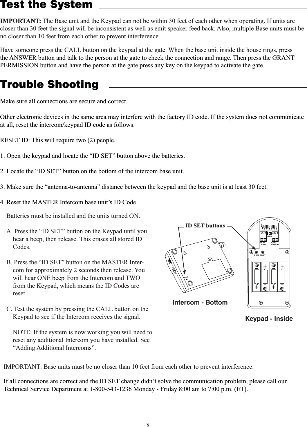
GTO Access Systems
>
MM136KP User Manual
Users Manual
Navigation menu
Upload a User Manual
Namespaces
Wiki Guide
HTML
PDF
Info
Views
User Manual
Discussion / Help
Navigation