GE Medical Systems Information Technologies 2014748 Medical Telemetry Transmitter worn on body User Manual 2001989 135A
GE Medical Systems Information Technologies Inc. Medical Telemetry Transmitter worn on body 2001989 135A
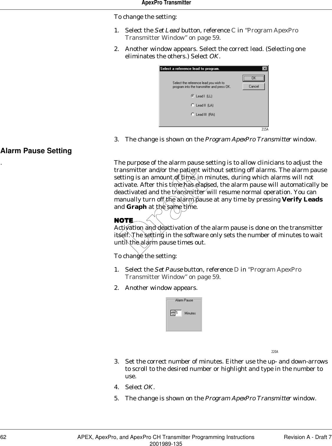
Contents
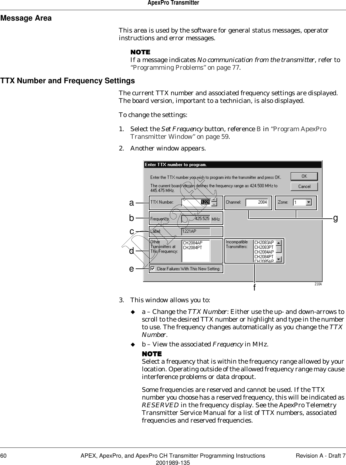
- 1. Users Manual 1 of 3
- 2. Users Manual 2 of 3
- 3. Users Manual 3 of 3 Safety
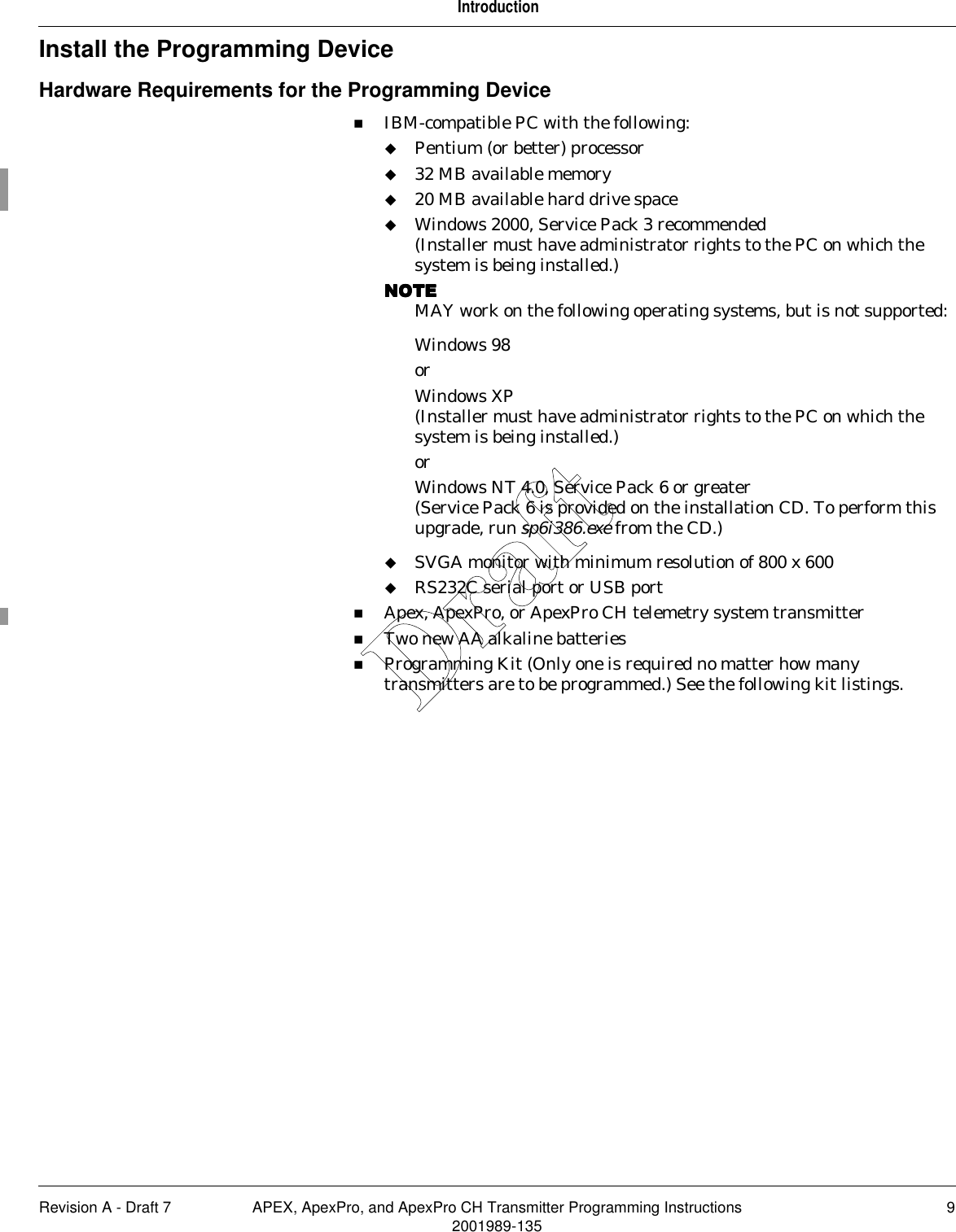
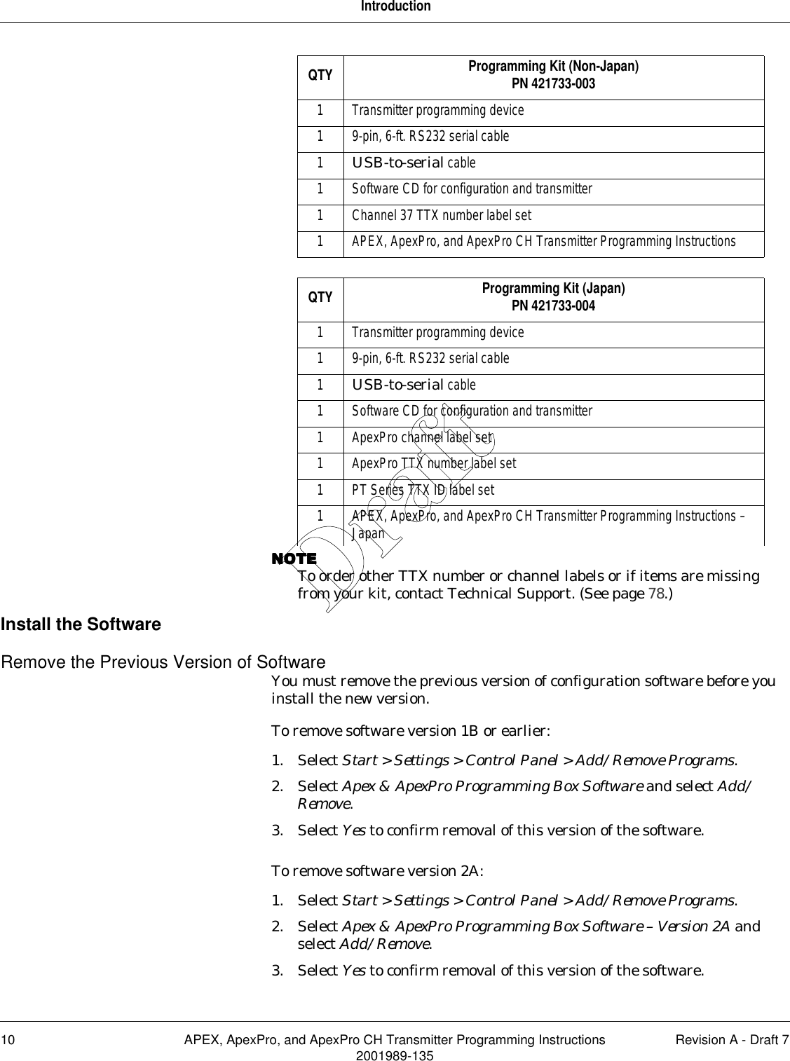
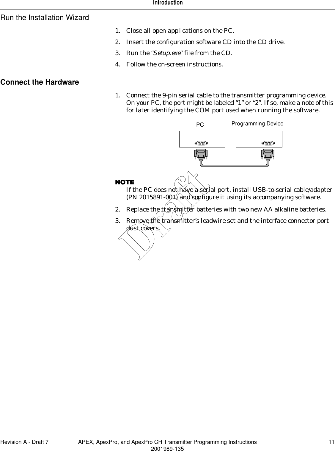
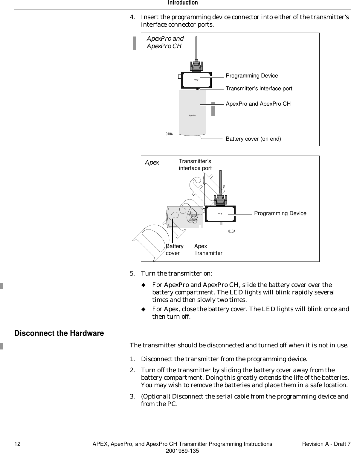
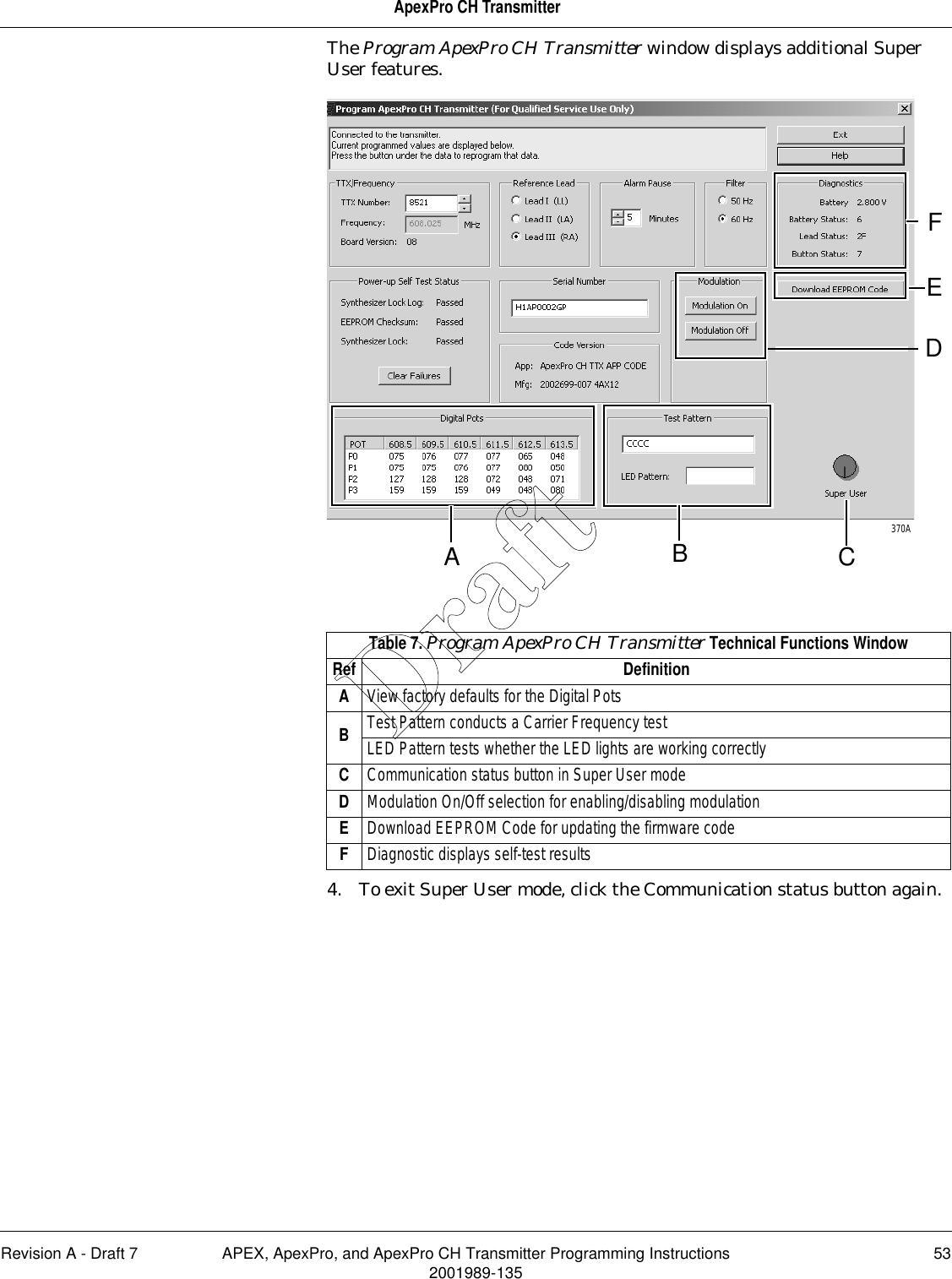
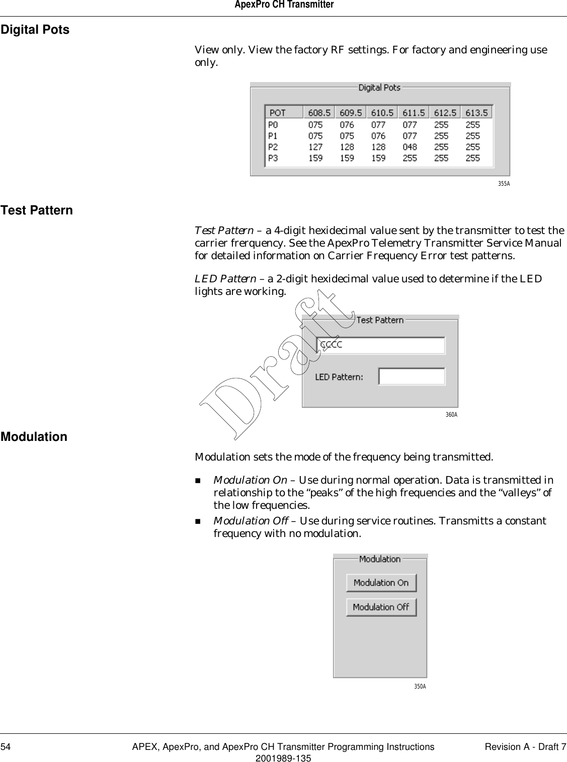
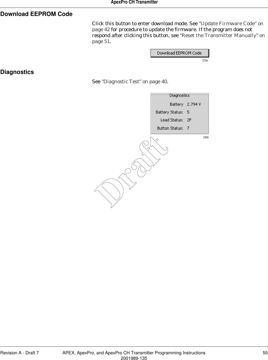
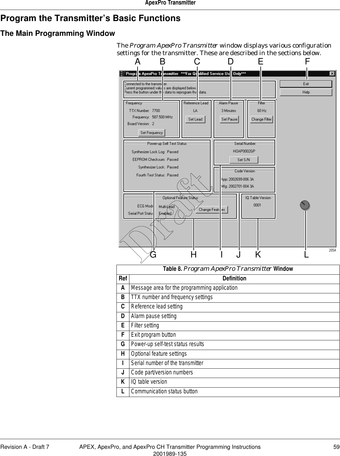
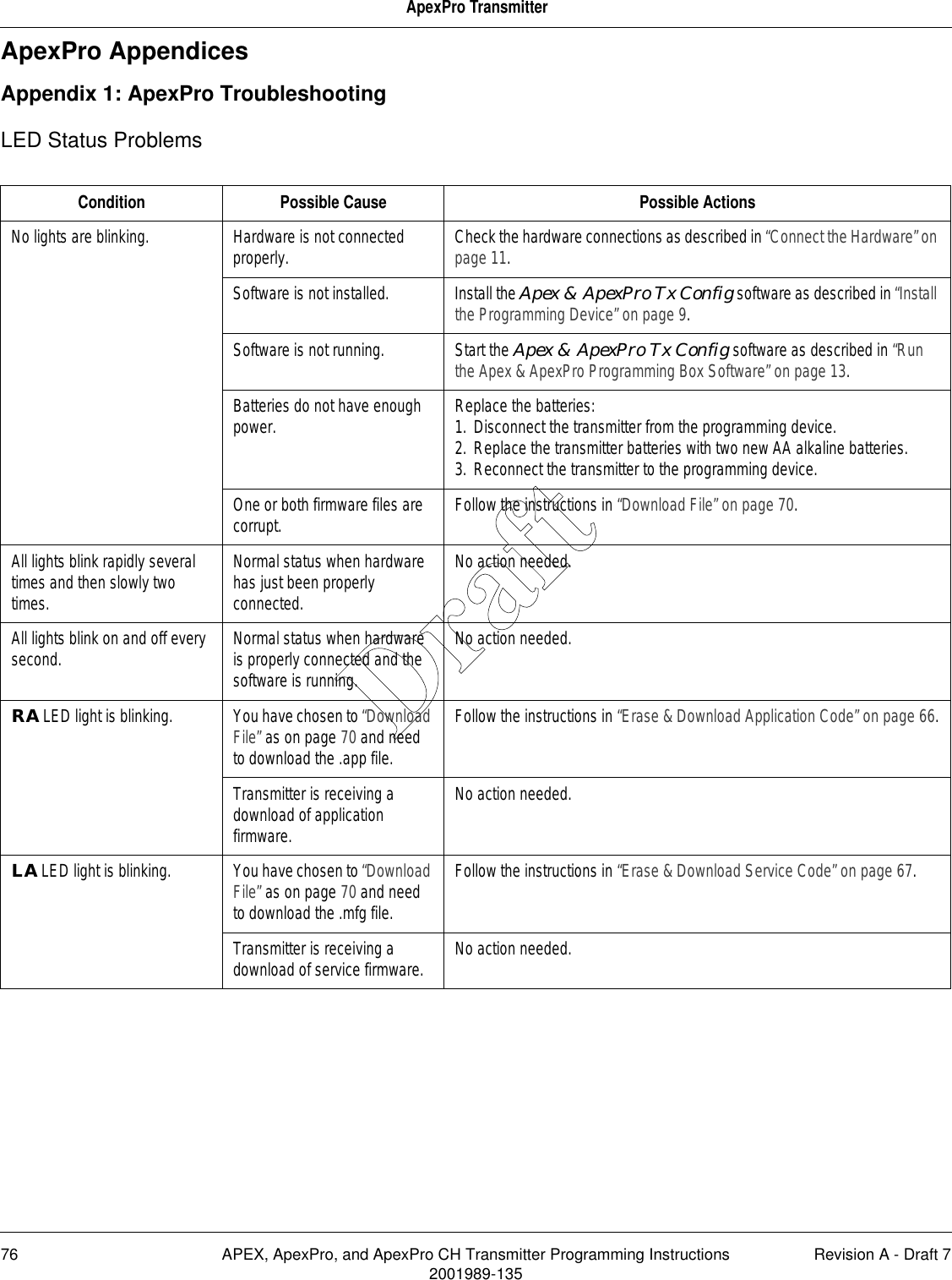
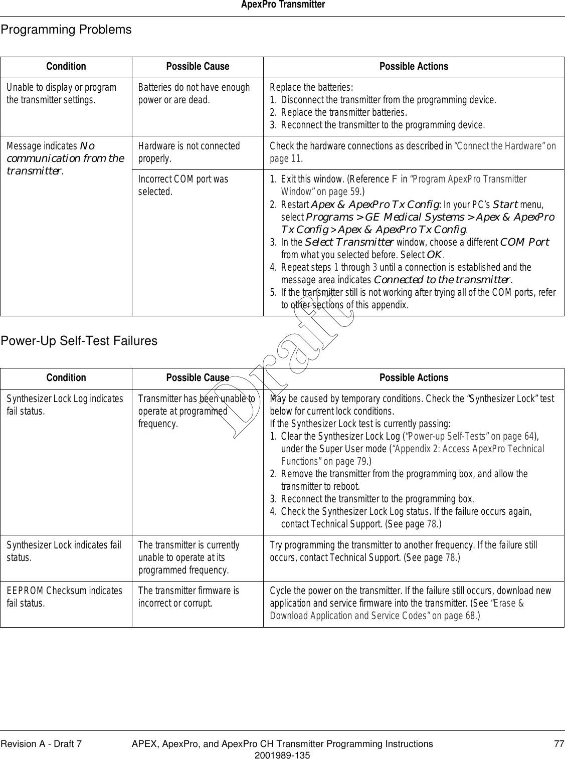
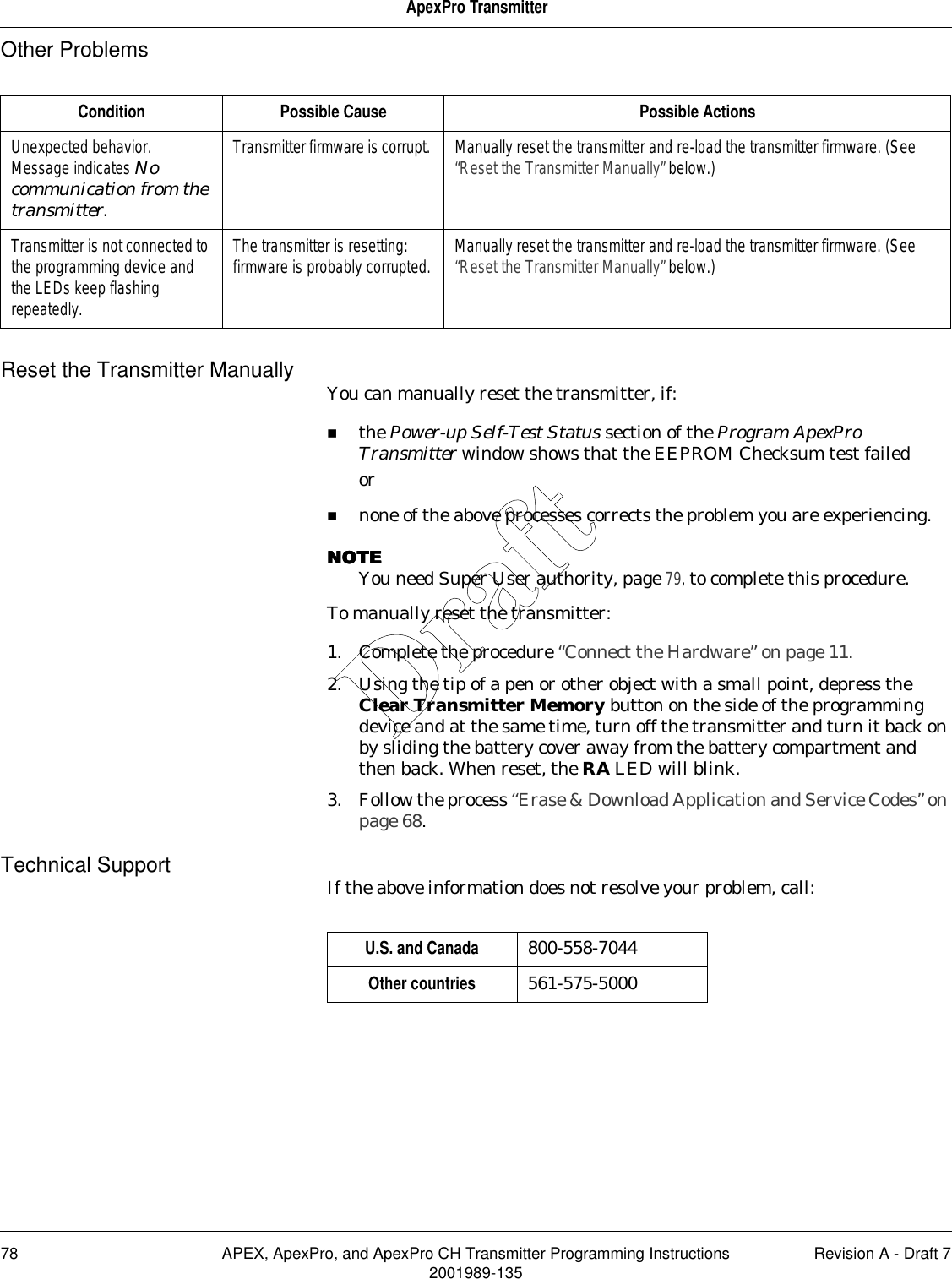
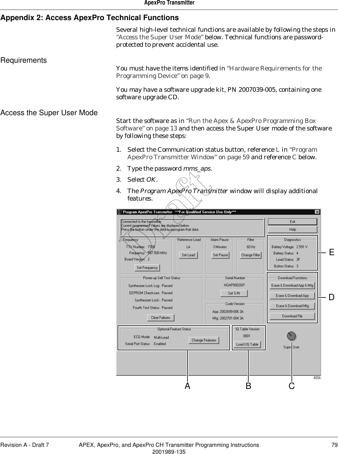
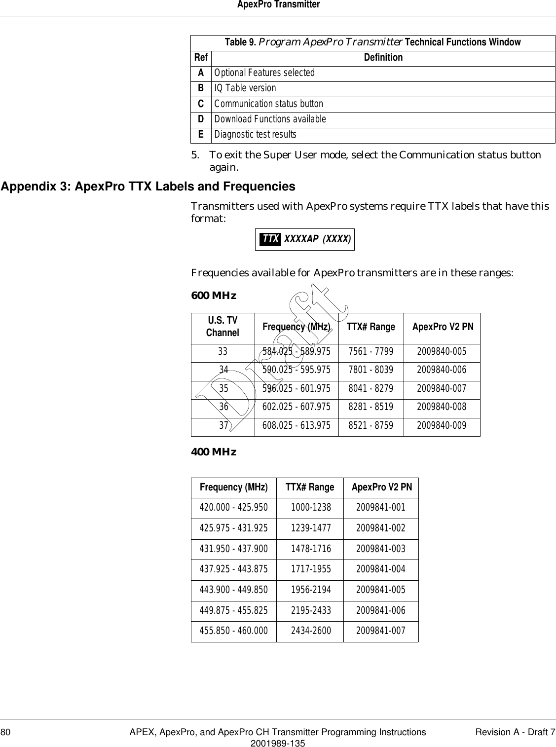
- 4. 2001989 135A APEX Manual DRAFT
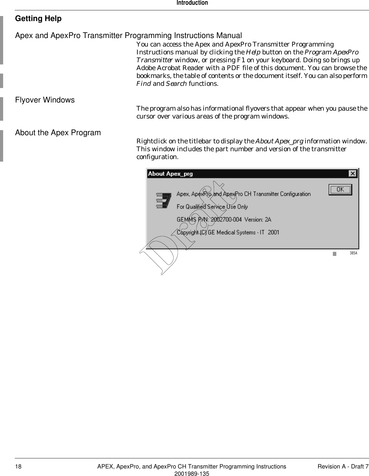
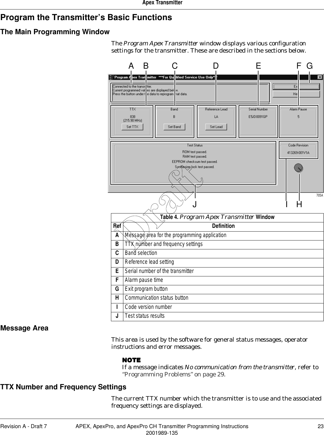
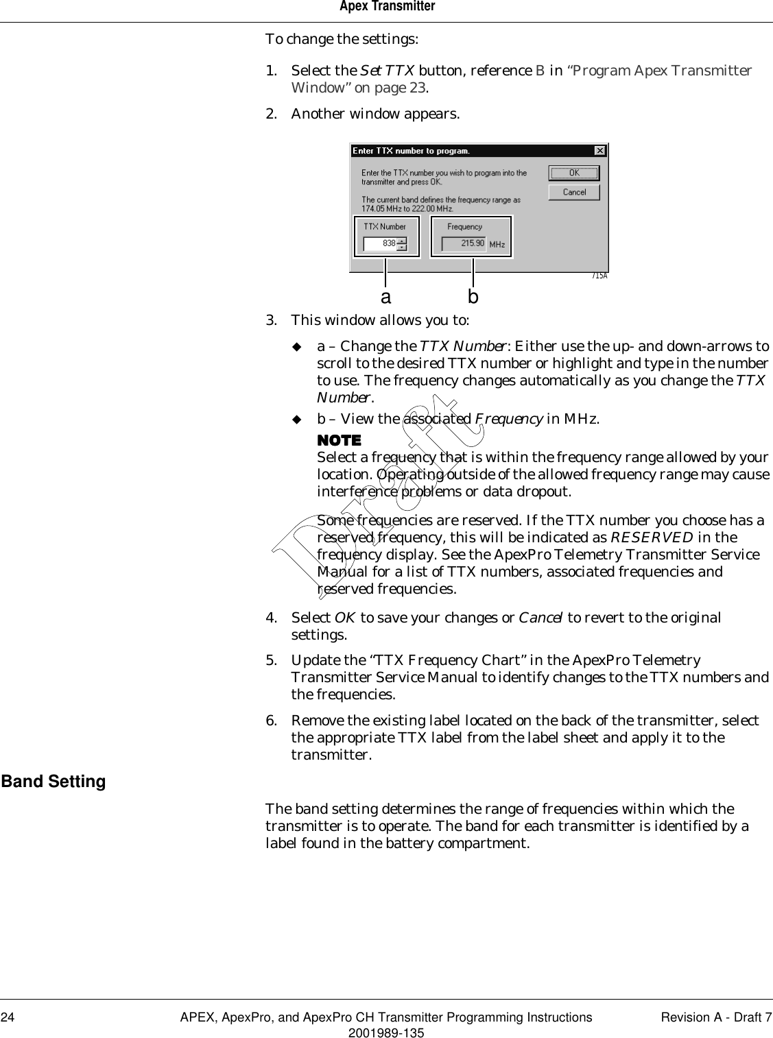
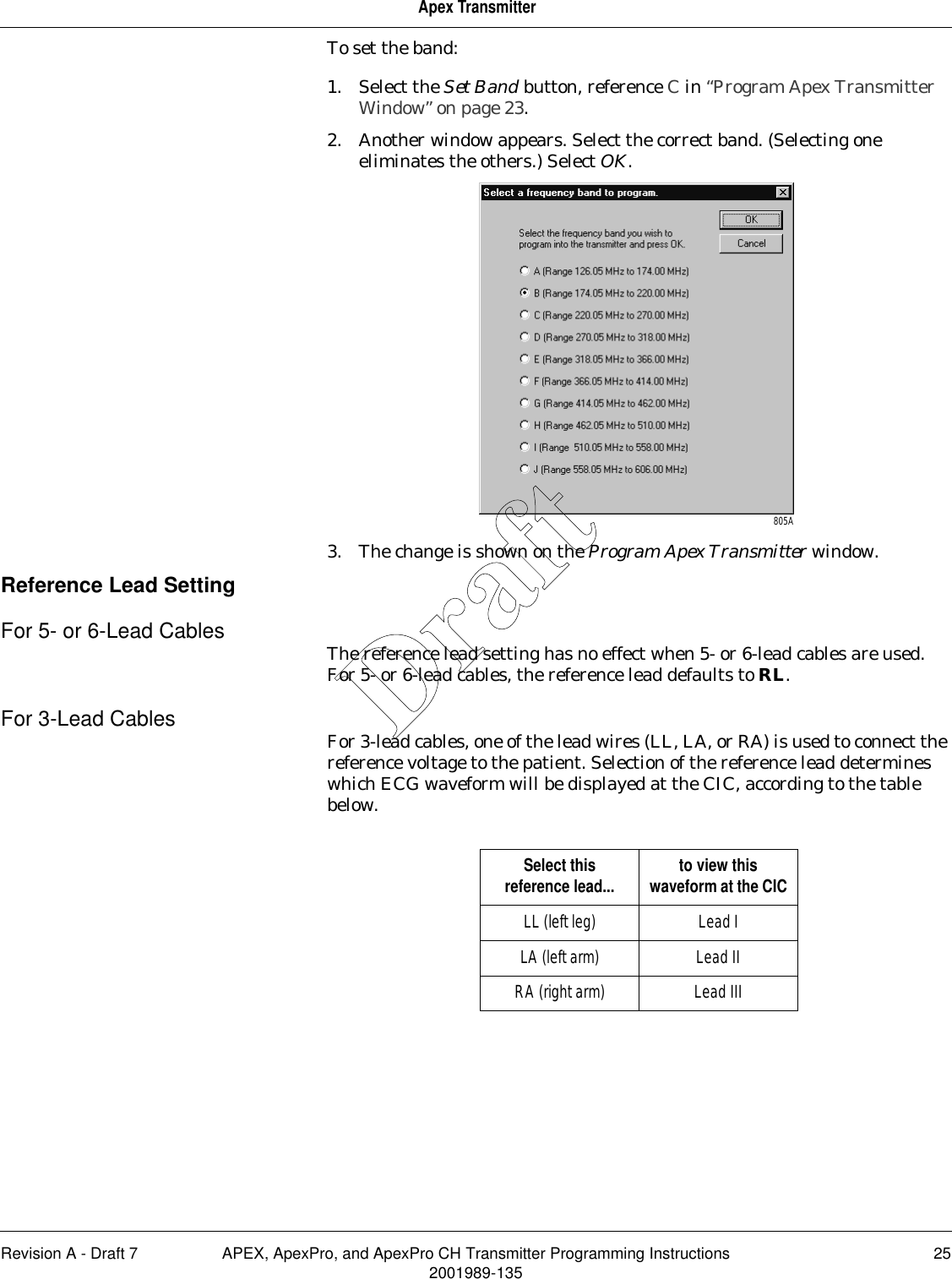
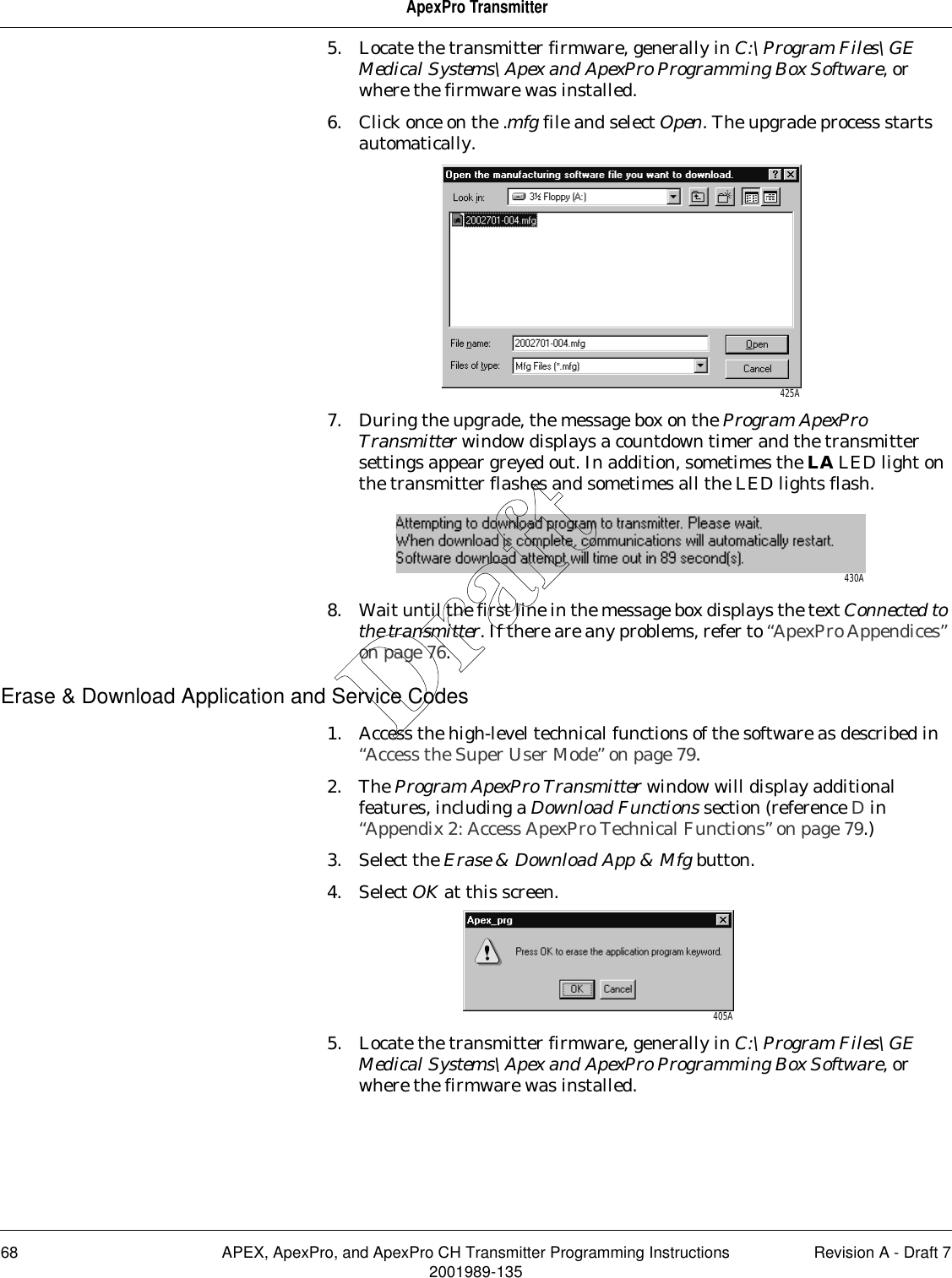
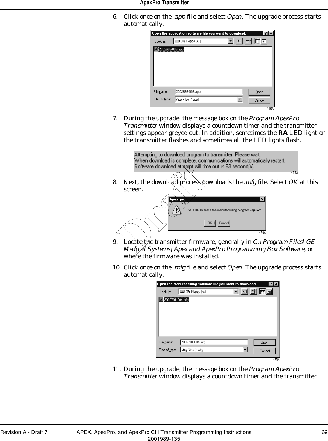
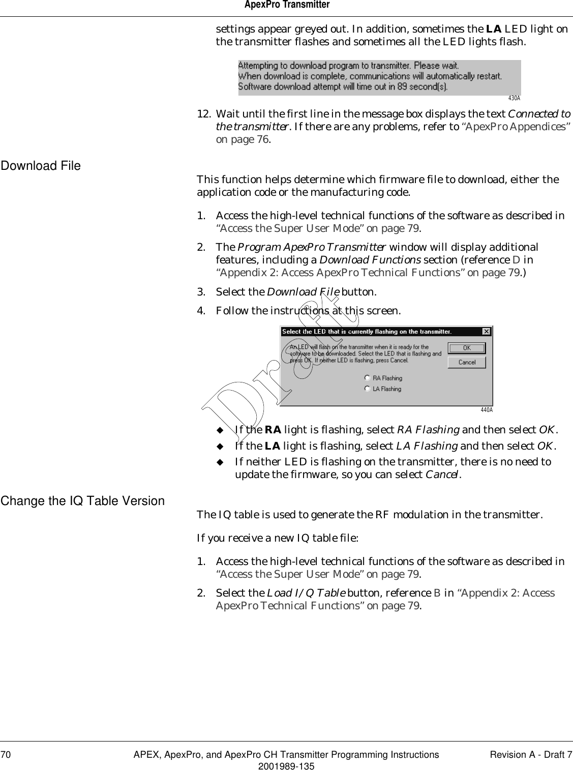
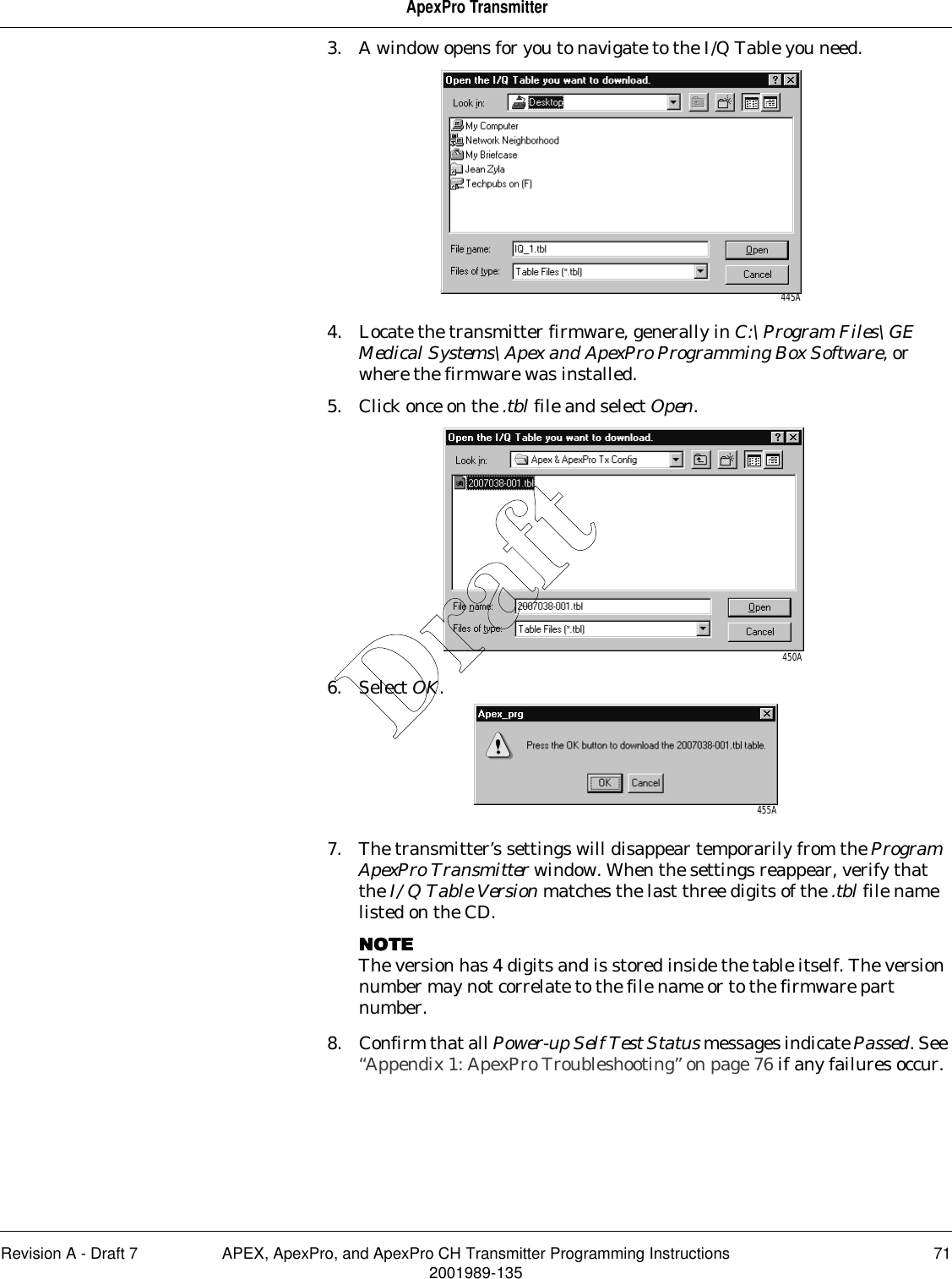
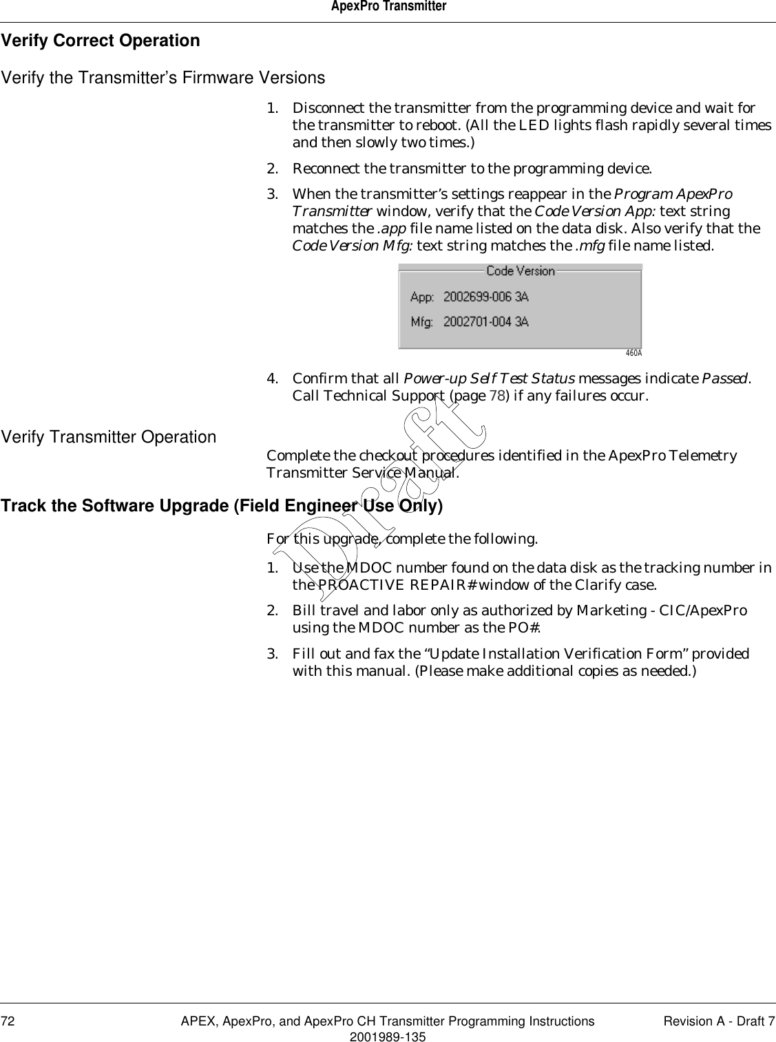
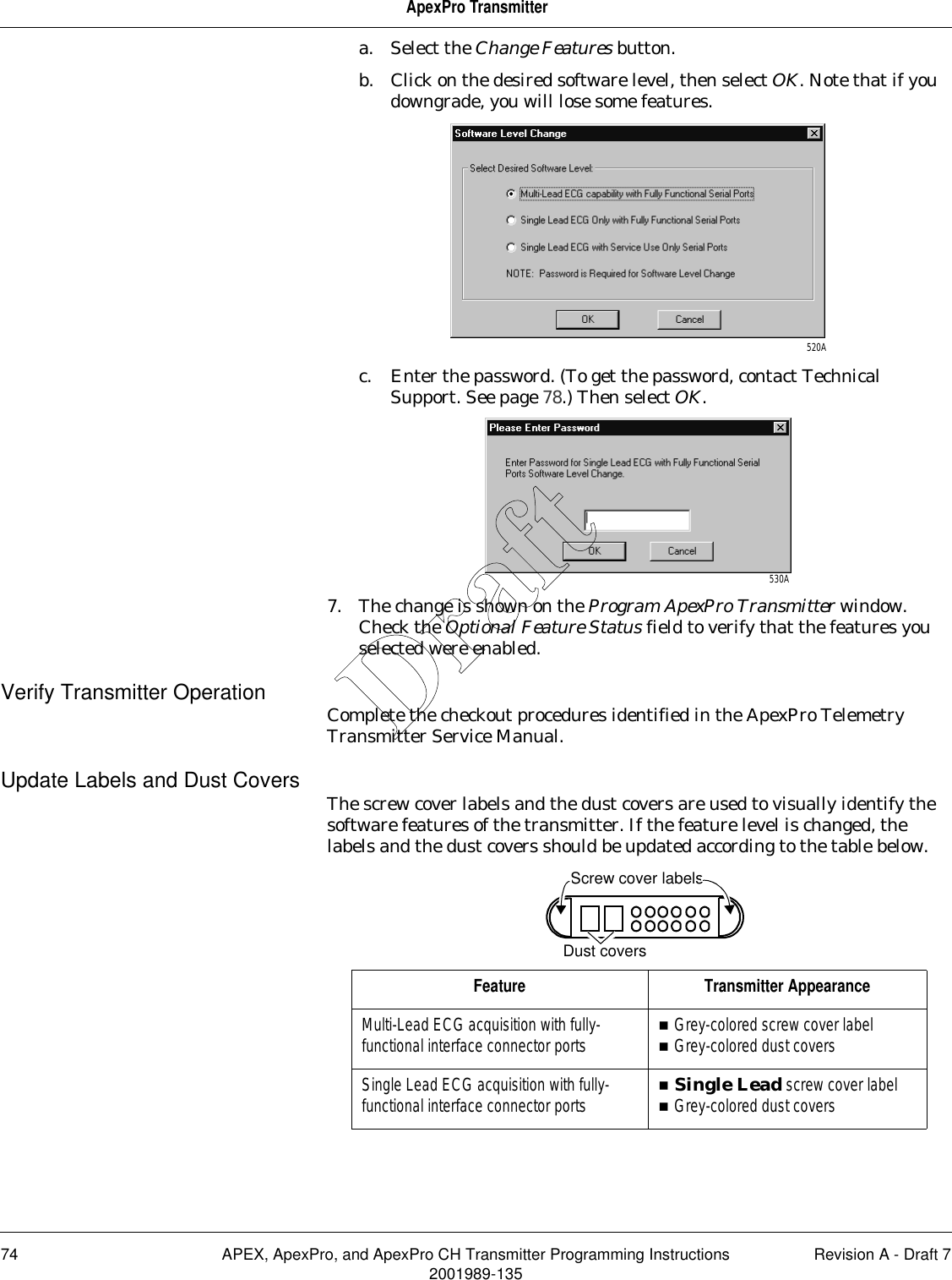
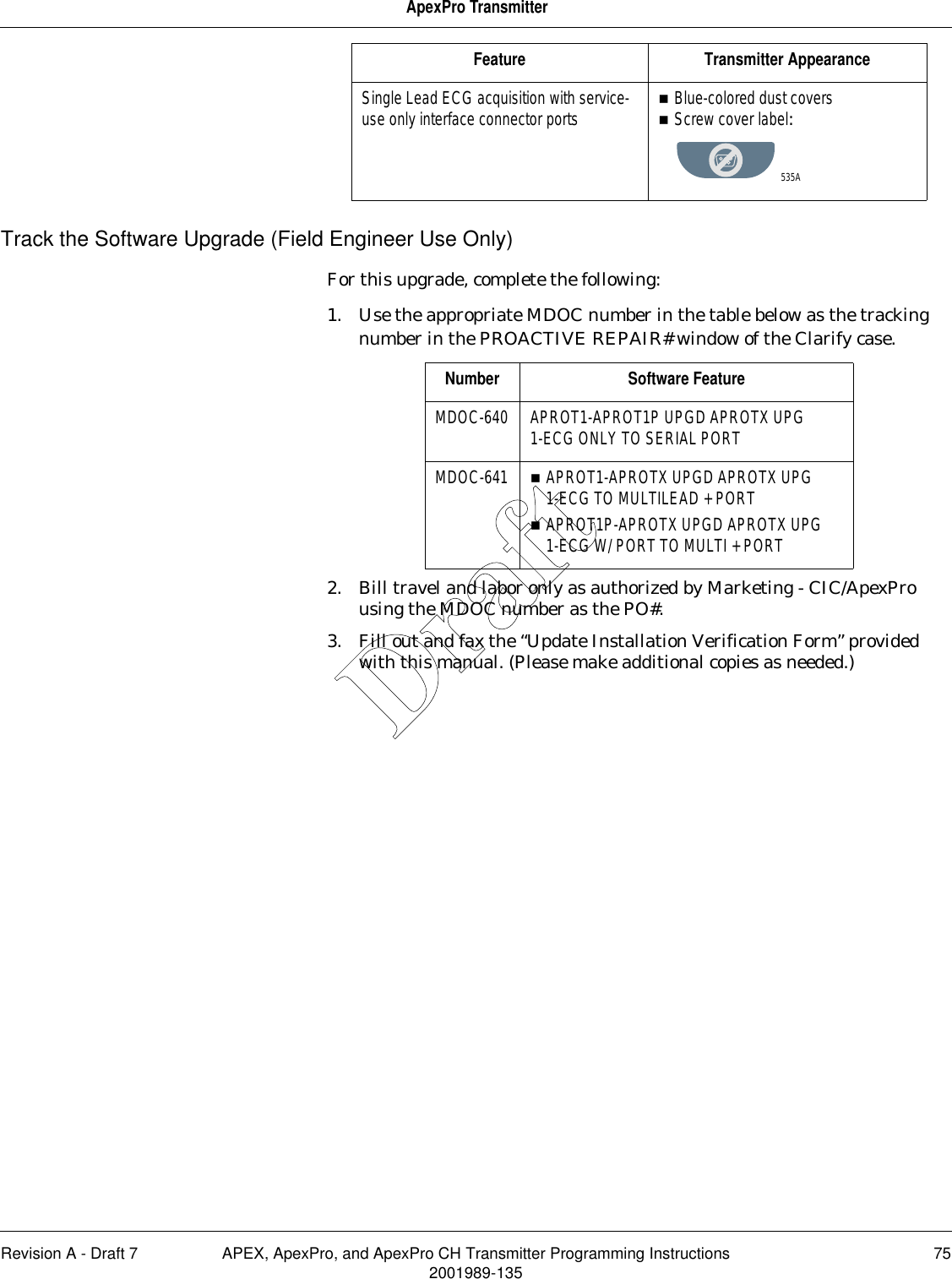
2001989 135A APEX Manual DRAFT