GE MDS DS-MERCURY900 Mercury 900 Wireless Transceiver User Manual
GE MDS LLC Mercury 900 Wireless Transceiver
GE MDS >
Contents
- 1. manual pt 1
- 2. manual pt 2
- 3. User Manual 1
- 4. User Manual 2
- 5. Users Manual Revised 121908 Part 1
- 6. Users Manual Revised 121908 Part 2
- 7. Users Manual Revised 121908 Part 3
Users Manual Revised 121908 Part 2
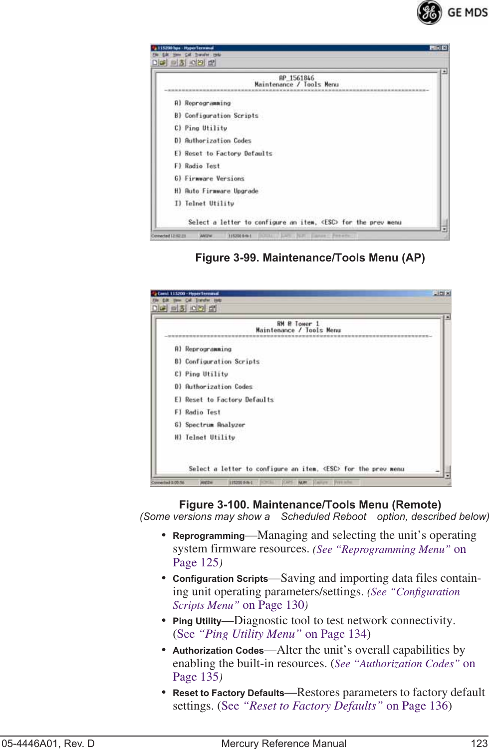
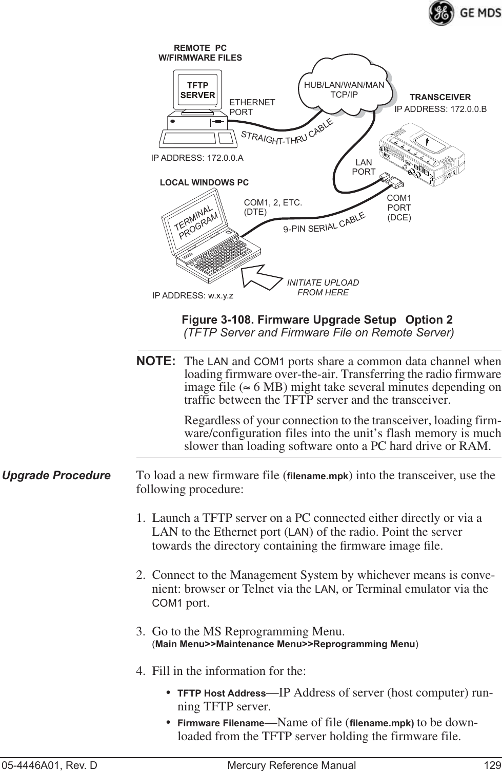
![05-4446A01, Rev. D Mercury Reference Manual 67Invisible place holderFigure 3-37. Frequency Control Menu(Mercury 3650 model only)•Frequency (Mercury 3650 only)—Used to set/display the radio’s operating frequency. MDS 3650 radios do not employ fre-quency hopping, thus the entry here is a specific RF operating channel. The allowable entry range is 3650.000000 to 3700.000000 MHz.•Frequency Mode—The unit can operate on one selected fre-quency or frequency hop. Remotes have the option of using a static hopping configuration or using the AP locations file to select an AP and perform hand-offs. For more information on hand-offs, see Table 3-2 on Page 70. Changing this parameter requires a radio reboot.[Static Hopping, Hopping with Hand-offs, Single Channel; Single Channel]NOTE: Frequency Mode Static Hopping on Access Points requiresTDD Sync Mode GPS Required.Channel/Frequency Allocations for Single Channel 900 MHz are shown in Table 3-1. The transceiver uses up to 14 channels (0-13) depending on the bandwidth used (1.75 MHz or 3.5 MHz).Table 3-1. Channel/Frequency Allocations Channel 1.75 MHz B/W 3.5 MHz B/W0 903.000000 904.0000001 904.800000 907.6000002 906.600000 911.4000003 908.600000 915.0000004 910.400000 918.6000005 912.200000 922.4000006 914.000000 926.000000](https://usermanual.wiki/GE-MDS/DS-MERCURY900.Users-Manual-Revised-121908-Part-2/User-Guide-1048763-Page-1.png)
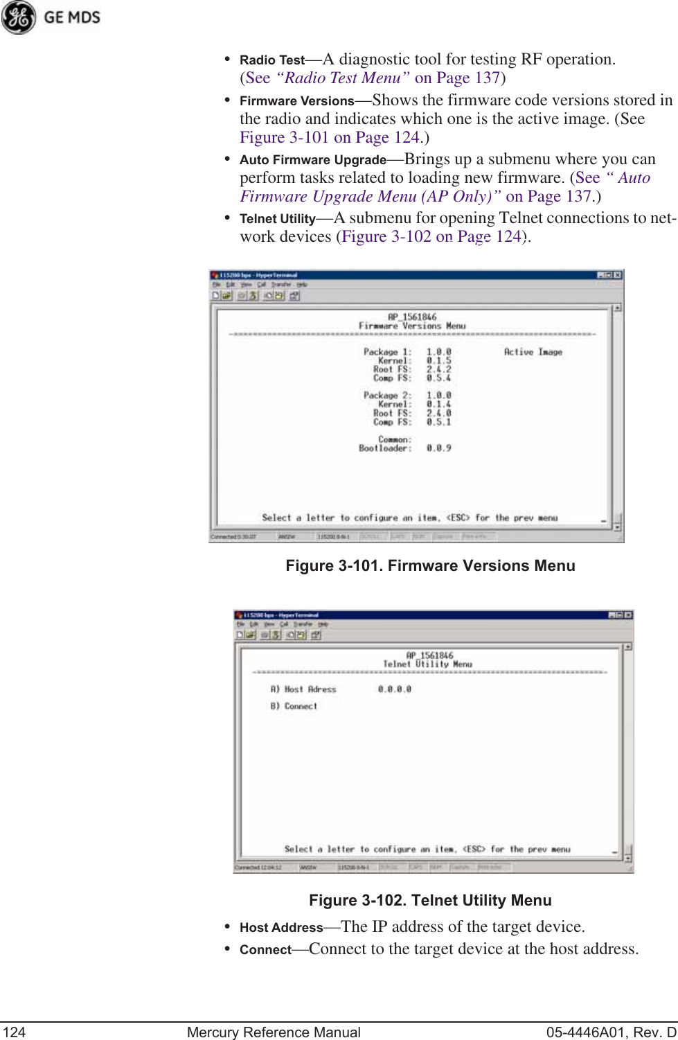
![68 Mercury Reference Manual 05-4446A01, Rev. D•RF Bandwidth—View/set the radio’s RF operating bandwidth. Radios are factory-configured for either 1.75 MHz or 3.5 MHz maximum bandwidth. Determine the factory configu-ration of a radio by viewing the “CONFIG” number on the label at the bottom of the radio. 1.75 MHz units will have a Configuration string starting with HGA/R9N1, and 3.5 MHz units will have a string starting with HGA/R9N3.The bandwidth setting on this menu does not necessarily have to match the configured bandwidth of the radio, but it is limited by it. That is, you can set a 3.5 MHz radio to either 1.75 or 3.5, but you can only set a 1.75 MHz radio to 1.75. Note that setting a 3.5 MHz bandwidth radio to operate at 1.75 MHz bandwidth will cause a slight degradation of inter-ference rejection capability. Note that this parameter is read-only when Frequency Mode is set to Hopping w/Hand-offs. [1.75MHz, 3.5MHz]The Mercury 3650 can operate at 1.75 MHz, 3.5 MHz, 5 MHz, or 7 MHz bandwidth. The unit uses a digital filter so that any unit can operate at any bandwidth.•Single Frequency Channel—The RF frequency that the inte-grated radio will operate on when in single frequency (non-hopping) mode. [0 to 6 for 3.5-MHz, 0 to 13 for 1.75-MHz; 0].•Frame Duration—Defines the over-the-air media access con-trol framing. Note that this parameter is read-only when Fre-quency Mode is set to Hopping w/Hand-offs. [5, 8, 10, or 20 msec; 20 msec]•Hop Pattern—Selects a pre-defined series of channels that is followed when hopping. Note that this parameter is read-only when Frequency Mode is set to Hopping w/Hand-offs.•Hop Pattern Offset—Inserts an offset into the hop pattern that is synchronized with the GPS. For example, if the offset is 0, the start of the pattern is aligned with the GPS timing. If the offset is 3, then the fourth hop of the pattern is aligned with the GPS timing. All of the APs that are part of a network should use the same pattern and each one should have its own offset. 7 916.0000008 917.8000009 919.60000010 921.40000011 923.40000012 925.20000013 927.000000Table 3-1. Channel/Frequency Allocations (Continued)Channel 1.75 MHz B/W 3.5 MHz B/W](https://usermanual.wiki/GE-MDS/DS-MERCURY900.Users-Manual-Revised-121908-Part-2/User-Guide-1048763-Page-2.png)
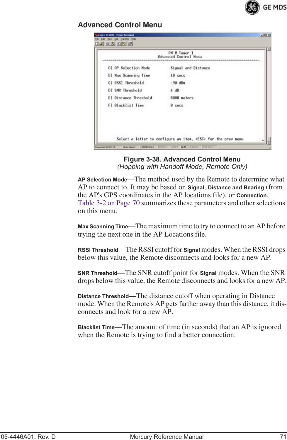
![05-4446A01, Rev. D Mercury Reference Manual 69In the diagram below, one Remote is configured for static hopping and will only associate with AP1 because they are both using Offset 0. The hand-off configured Remote, using its AP Locations file, may connect to AP1, AP2, or AP3. The Remote does this by determining the Offset for each AP, then configuring its radio.•Current AP (Remote only)—Shows the name of the AP that the Remote is trying to associate with. Note that this param-eter is read-only when Frequency Mode is set to Hopping w/Hand-offs.•TDD Sync Mode (AP only)—Indicates if the Access Point’s trans-missions should synchronize with the GPS timing. Configure this parameter to GPS Required when the AP is configured for Static Hopping. TDD Sync Mode (Time-Division Duplex) is use-ful in eliminating same-network interference for multiple-AP installations. When enabled, all AP transmissions are synchro-nized using GPS timing information. The result is that no AP transmits while another is receiving, which prevents AP-to-AP interference. Changing this parameter requires a radio reboot.[Free Run, GPS Required; Free Run] Note: Do not use the Prefer GPS setting.•Channel Selection (AP only)—Opens a submenu where you can specify channel usage.•External GPS PPS Signal—Indicates whether or not an external Pulse Per Second (PPS) signal is available. The setting may be changed by pressing the spacebar after selection of the menu item. This allows the radio to use the proper timing scheme when frequency hopping.•Advanced Control (Remote only)—Brings up a submenu (see Figure 3-38) where additional communication parameters may be set.AP 1 Pattern A Offset 0 AP 2 Pattern A Offset 1 AP 3 Pattern A Offset 2 RM Static Hopping Offset 0 RM Hopping w/ Hand-offs](https://usermanual.wiki/GE-MDS/DS-MERCURY900.Users-Manual-Revised-121908-Part-2/User-Guide-1048763-Page-3.png)
![70 Mercury Reference Manual 05-4446A01, Rev. D•Hardware Filter (900 MHz only)—This field provides a read-only indication of the maximum bandwidth of the radio. [1.75 MHz or 3.5 MHz]Hand-Off Mode Parameters In a mobile or portable application, a Remote radio can move and asso-ciate with different APs depending on its location. The process by which the Remote ends the connection with one AP and begins a connection with another AP is called “hand-off.” Table 3-2 lists the hand-off parameters for Remote transceivers and explains how they operate under different signal conditions. NOTE: In Table 3-2 above, modes using the “Closest 3 APs” firstattempt to connect to the closest AP. If after the maximumnumber of scanning seconds (Max. Scanning Seconds) a link isnot established, then the next closest AP is chosen. If afteranother maximum number of scanning seconds a link is notestablished, then the third closest AP is chosen. If a link still isnot established, the Remote again chooses the closest AP andcontinues this cycle until it is associated to one of the APs.NOTE: In Table 3-2 above, modes which use the RSSI and SNR Thresh-olds use them in an “or” logic fashion. That is, if the RSSI isbelow the set threshold OR the SNR is below threshold, theRemote drops the current AP.Table 3-2. Remote Hand-Off ParametersStrict DistanceStrict ConnectionStrict SignalSignal andDistanceSignal, Dis-tance, and BearingDescription The Remote always chooses the closest AP regardless of connection status, RSSI, etc.The Remote will only choose a new AP when the modem link is lost.The Remote chooses a new AP when the modem link is lost or when the RSSI or SNR falls below the threshold. The Remote then chooses the closest AP.Operates the same way as the Strict SIgnal method except that the current AP is abandoned only if the next AP is within the distance threshold.Operates the same way as the Signal and Distance method except that the current AP is abandoned only if the bearing is away from the current AP.AP(s) Used(see note be-low Table 3-2)Only closest AP. Closest 3 APs. Closest 3 APs. Closest 3 APs; AP must be within Distance Threshold.Closest 3 APs; AP must be within Distance Threshold.Max. Scanning SecondsN/A Applicable Applicable Applicable ApplicableRSSI ThresholdN/A N/A Applicable Applicable ApplicableSNR Threshold N/A N/A Applicable Applicable ApplicableDistanceThresholdN/A N/A N/A Applicable ApplicableBlacklist Time N/A Applicable Applicable Applicable Applicable](https://usermanual.wiki/GE-MDS/DS-MERCURY900.Users-Manual-Revised-121908-Part-2/User-Guide-1048763-Page-4.png)
![72 Mercury Reference Manual 05-4446A01, Rev. DAdvanced Configuration Menu Invisible place holderFigure 3-39. Advanced Configuration Menu•Adaptive Modulation—Enables automatic selection of modulation and FEC rate based on SNR. [enabled, disabled; enabled]•Protection Margin—A number of decibels of SNR added to the minimum SNR required for a given modulation and FEC rate. See “Modulation Protection and Hysteresis Margins” on Page 73 for more information. [0-50; 3]•Hysteresis Margin—A number of decibels of SNR added to the maximum SNR required before shifting to the next higher mod-ulation and FEC rate. See “Modulation Protection and Hyster-esis Margins” on Page 73 for more information. [0-50; 3]•Data Compression—This setting determines whether over-the-air data packets will be compressed. [enabled, disabled; enabled]•Max Modulation—Sets the highest modulation speed the trans-ceiver will use.[BPSK, QPSK-1/2, QPSK-3/4, 16QAM-1/2, 16QAM-3/4, 64QAM-2/3; QAM16-3/4]•Cyclic Prefix (AP only)—Amount of additional information added to the over-the-air packets to mitigate the effects of chan-nel multipath. [1/4, 1/8, 1/16,1/32; 1/16]•Channel Type (AP only)—This parameter, available on Access Point units, must be set appropriately according to the signal conditions of a network. For installations with strong signals, low interference, and minimal fading, set the Channel Type parameter to Static. This setting is generally appropriate for Access Points whose Remotes are in fixed locations. It supports a large offered payload with high packet rates. For installations with significant interference and fading or nomadic/mobile Remotes, set the Channel Type parameter to Dynamic. [Static, Dynamic; Static]](https://usermanual.wiki/GE-MDS/DS-MERCURY900.Users-Manual-Revised-121908-Part-2/User-Guide-1048763-Page-6.png)
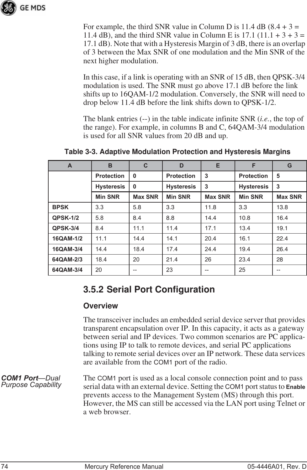
![05-4446A01, Rev. D Mercury Reference Manual 73•ARQ (AP only)—Enables the Automatic Repeat Request func-tion. [enable, disable; enabled]•ARQ Window Size (AP only)—The maximum number of blocks to send before receiving an acknowledgement. [1—1024; 512]•ARQ Block Size (AP only)—ARQ is applied to payload data in blocks of this size. [4—2040; 256]•ARQ Block Lifetime (AP only)—ARQ blocks are valid for this length of time. [0—655; 655]•ARQ Transmitter Delay (AP only)—The length of time the trans-mitter waits before repeating an unacknowledged packet.[1—655; 35]•ARQ Receiver Delay (AP only)—The length of time the receiver waits before repeating an unacknowledged packet. [1—655; 35]•Downlink Percentage (AP only)—The percentage of link time given to downstream traffic. It should be set to 50% when Adap-tive Split is set to enabled. [10-90%; 50%]•Adaptive Split (AP only)—The adaptive split feature provides improved link utilitization and throughput for burst payload traffic. The Mercury is a TDD system and normally allocates 50% of its capacity to the downlink and 50% to the uplink. When adaptive split is enabled, the Media Access Controller (MAC) in the Access Point monitors the traffic flow continu-ously in the downlink and uplink directions. The MAC automat-ically modifies the downlink split in response to the traffic load. When more traffic is flowing upstream, the downlink split changes to allocate additional capacity to the uplink. When more traffic is flowing downstream, the downlink gets addi-tional capacity. If TDD synchronization is used to synchronize Access Points and minimize inter-Access Point interference, Adaptive Split should be disabled. [enabled, disabled; enabled]Modulation Protection and Hysteresis MarginsTable 3-3 on Page 74 shows the relationship between the radio’s Protec-tion Margin, Hysteresis Margin, and the SNR range allowed for each form of modulation.Column A lists the available modulation types for the radio, while col-umns B and C show the minimum SNR range required to operate in each modulation. For example, an SNR of 5.8 dB in Column B is required for QPSK modulation with an FEC rate of 1/2. An SNR of 8.4 dB is required for QPSK modulation with an FEC rate of 3/4.Columns B and C have a Hysteresis Margin of 0 dB. This means there is no overlap between the maximum SNR for BPSK (5.8 dB) and the minimum SNR for QPSK-1/2 (5.8 dB).Columns D and E show the SNR ranges with a Protection Margin and Hysteresis Margin of 3 dB. The Protection Margin is added to each value in Columns B and C to get the corresponding value in Columns D and E. The Hysteresis Margin is then added to the Max SNR value.](https://usermanual.wiki/GE-MDS/DS-MERCURY900.Users-Manual-Revised-121908-Part-2/User-Guide-1048763-Page-7.png)
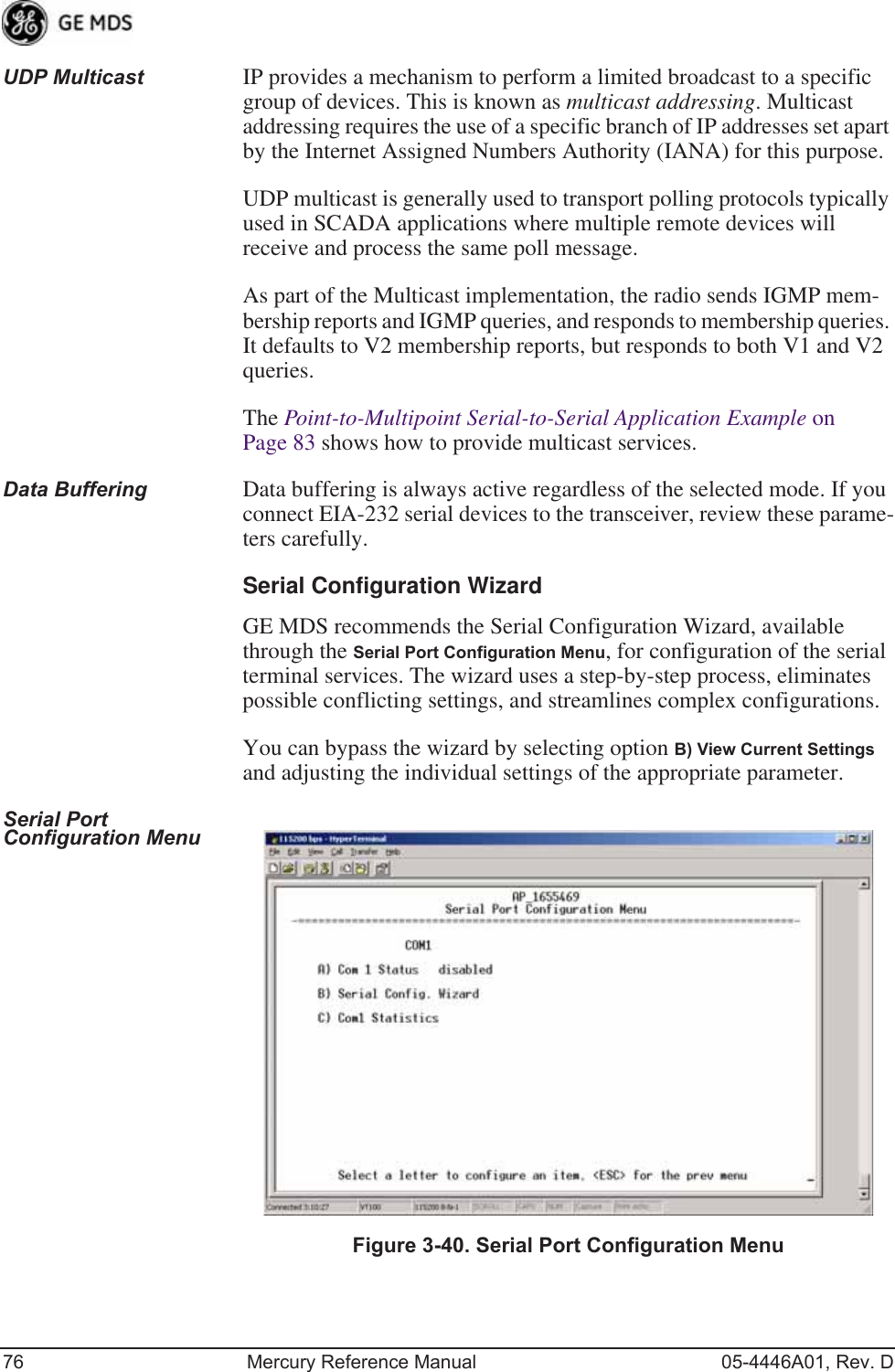
![05-4446A01, Rev. D Mercury Reference Manual 77 Figure 3-41. Serial Configuration Wizard•Begin Wizard—Tool for configuring serial ports using a step-by-step process.•View Current Settings—Displays all setable options. Varies depending on the selected IP protocol.Configuring for UDP Point-to-Multipoint Invisible place holderFigure 3-42. UDP Point-to-Multipoint MenuUse UDP point-to-multipoint to send a copy of the same packet to mul-tiple destinations, such as in a polling protocol.•Status—Enable/Disable the serial data port.•Mode—The type of IP port offered by the transceiver’s serial device server. [TCP, UDP; TCP]](https://usermanual.wiki/GE-MDS/DS-MERCURY900.Users-Manual-Revised-121908-Part-2/User-Guide-1048763-Page-11.png)
![78 Mercury Reference Manual 05-4446A01, Rev. D•RX IP Port—Receive IP data from this source and pass it through to the connected serial device. The port number must be used by the application connecting to local TCP or UDP socket. [Any valid IP port; 30010]•TX IP Address (used instead of Local IP Address when using UDP Point-to-Multipoint)— Configure with a valid Multi-cast address (224.0.0.0–239.255.255.255). IP packets received with a matching destination address are processed by this unit. [Any legal IP address; 0.0.0.0]•TX IP Port (used instead of Local IP Port when using UDP Point-to-Multipoint)—This port number must match the number used by the application connecting to local TCP or UDP socket. [1-64,000; 30010]•Baud Rate—Data rate (payload) for the COM port, in bits-per-second. [1,200—115,200; 19200] •Byte Format—Formatting of data bytes, representing data bits, parity and stop bits. [7N1, 7E1, 7O1, 8N1, 8E1, 8O1, 8N1, 7N2, 7E2, 7O2, 8N2, 8E2, 8O2; 8N1]•Buffer Size—Maximum amount of characters that the Remote end buffers locally before transmitting data through the serial port. [1—255; 255]•Inter-Packet Delay—Amount of time that signal the end of a message, measured in tenths of a second. [default = 1 (that is, 1/10th of a second)]•Commit Changes and Exit Wizard—Save and execute changes made on this screen (shown only after changes have been entered). Invisible place holderFigure 3-43. UDP Point-to-Point MenuConfiguring for UDP Point-to-Point Use UDP point-to-point configuration to send information to a single device.•Status—Enable/Disable the serial data port.](https://usermanual.wiki/GE-MDS/DS-MERCURY900.Users-Manual-Revised-121908-Part-2/User-Guide-1048763-Page-12.png)
![05-4446A01, Rev. D Mercury Reference Manual 79•Mode—UDP Point-to-Point. This is the type of IP port offered by the transceiver’s serial device server. [TCP, UDP; TCP]•RX IP Port—Port number where data is received and passed through to the serial port. The application connecting to this transceiver must use this port number.[1—64,000; 30010]•TX IP Address—Data received through the serial port is sent to this IP address. To reach multiple Remotes in the network, use UDP Point-to-Multipoint. [Any legal IP address; 0.0.0.0]•TX IP Port—The destination IP port for data packets received through the serial port on the transceiver. [1—64,000; 30010]•Talkback Enable—Talkback is a mode where the radio returns a serial message received within a time-out period back to the last address of an incoming UDP message. If the time-out expires, the unit sends the serial data to the configured address. [Enable, Disable; Disabled]•Baud Rate—Data rate (payload) for the COM port, in bits-per-second. [1,200—115,200; 19200] •Byte Format—Formatting of data bytes. Data bits, parity and stop bits. [7N1, 7E1, 7O1, 8N1, 8E1, 8O1, 8N1, 7N2, 7E2, 7O2, 8N2, 8E2, 8O2; 8N1]•Buffer Size—Maximum amount of characters that the Remote end buffers locally before transmitting data through the serial port. [1—255; 255]•Inter-Packet Delay—Amount of time that signal the end of a message, measured in tenths of a second. [default = 1 (that is, 1/10th of a second)]•Commit Changes and Exit Wizard—Save and execute changes made on this screen (shown only after changes have been entered).](https://usermanual.wiki/GE-MDS/DS-MERCURY900.Users-Manual-Revised-121908-Part-2/User-Guide-1048763-Page-13.png)
![80 Mercury Reference Manual 05-4446A01, Rev. DConfiguring for TCP Mode Invisible place holderFigure 3-44. TCP Client Menu (Remote)•Status—Enable/Disable the serial data port. •Mode—TCP Client. This is the type of IP port offered by the transceiver’s serial device server. [TCP, UDP; TCP]•TX IP Address—The IP address to be used as a destination for data received through the serial port.[Any legal IP address; 0.0.0.0]•TX IP Port—The destination IP port for data packets received through the serial port on the transceiver.[Any valid IP port; 30010]•TCP Keepalive—Amount of time (in seconds) that the trans-ceiver waits for data before terminating the TCP session. [0—600; 600]•Baud Rate—Data rate (payload) for the COM port, in bits-per-second. [1,200—115,200; 19200] •Byte Format—Interface signaling parameters. Data bits, parity and stop bits. [7N1, 7E1, 7O1, 8N1, 8E1, 8O1, 8N1, 7N2, 7E2, 7O2, 8N2, 8E2, 8O2; 8N1]•Buffer Size—Maximum amount of characters that the Remote end buffers locally before transmitting data through the serial port. [1—255; 255]•Inter-Frame Packet Delay—A measurement representing the end of a message, measured in tenths of a second.[default = 1 (that is, 1/10th of a second)]•Commit Changes and Exit Wizard—Save and execute changes made on this screen (shown only after changes have been entered).](https://usermanual.wiki/GE-MDS/DS-MERCURY900.Users-Manual-Revised-121908-Part-2/User-Guide-1048763-Page-14.png)
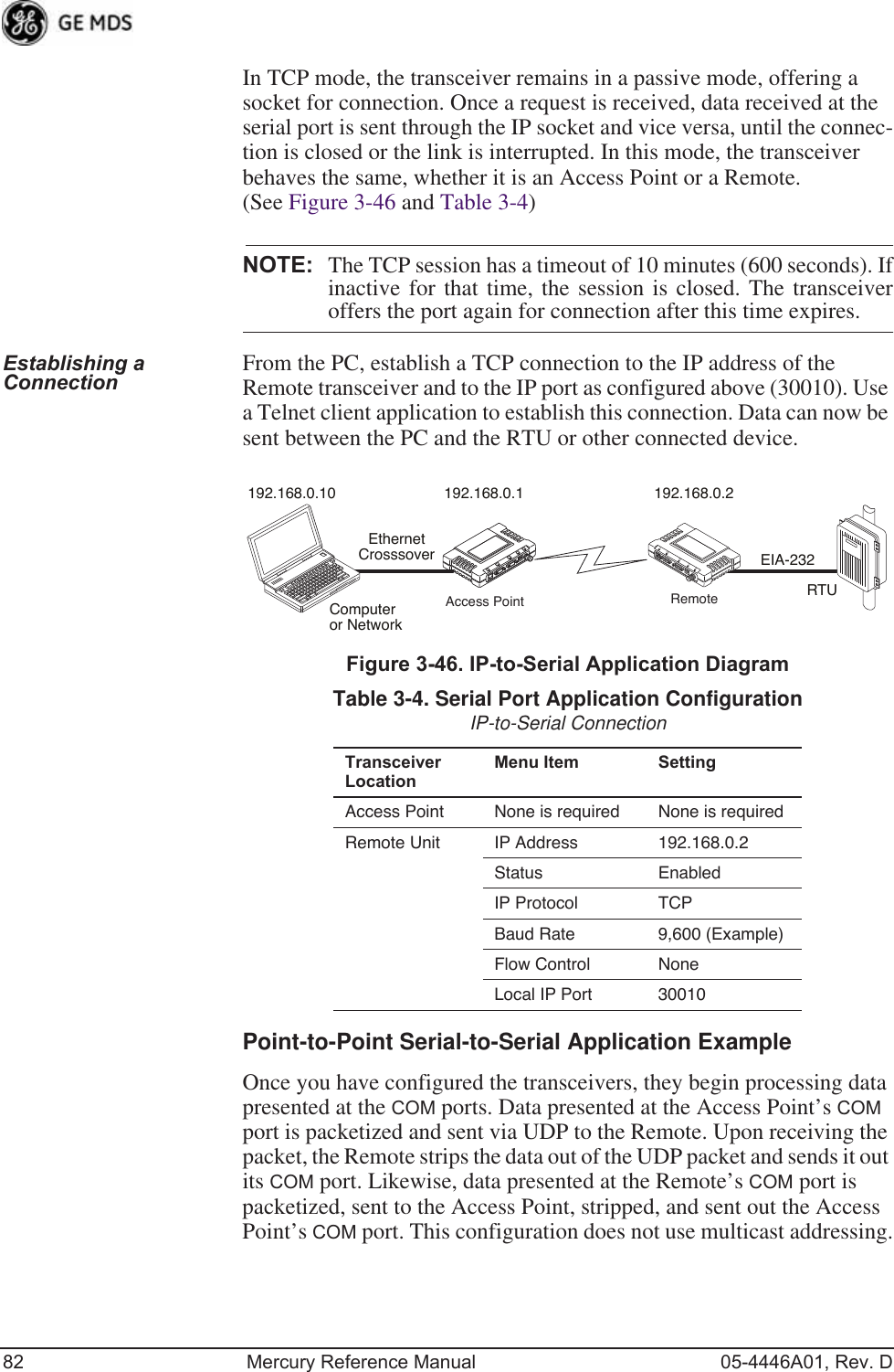
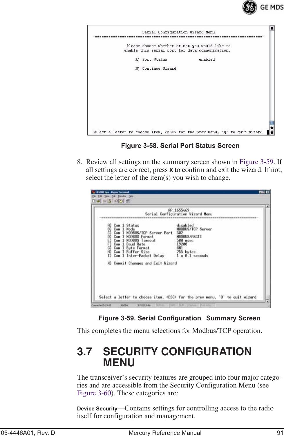
![05-4446A01, Rev. D Mercury Reference Manual 81Invisible place holderFigure 3-45. TCP Server Menu (AP)•Status—Enable/Disable the serial data port.•Mode—TCP Server. This is the type of IP port offered by the transceiver’s serial device server. [TCP, UDP; TCP]•RX IP Port—Receive IP data from this source and pass it through to the connected serial device. The application con-necting to the local TCP or UDP socket must use this port number.[Any valid IP port; 30010]•Baud Rate—Data rate (payload) for the COM port, in bits-per-second. [1,200—115,200; 19200] •Byte Format—Interface signaling parameters. Data bits, parity and stop bits. [7N1, 7E1, 7O1, 8N1, 8E1, 8O1, 8N1, 7N2, 7E2, 7O2, 8N2, 8E2, 8O2; 8N1]•Buffer Size—Maximum amount of characters that the Remote end buffers locally before transmitting data through the serial port. [1—255; 255]•Inter-Packet Delay—Amount of time that signal the end of a message, measured in tenths of a second. [default = 1 (that is, 1/10th of a second)]•Commit Changes and Exit Wizard—Save and execute changes made on this screen (shown only after changes have been entered).IP-to-Serial Application ExampleYou must choose UDP or TCP to establish communications. This depends on the type of device you are communicating with at the other end of the IP network. In this example, we will use TCP to illustrate its use.](https://usermanual.wiki/GE-MDS/DS-MERCURY900.Users-Manual-Revised-121908-Part-2/User-Guide-1048763-Page-15.png)
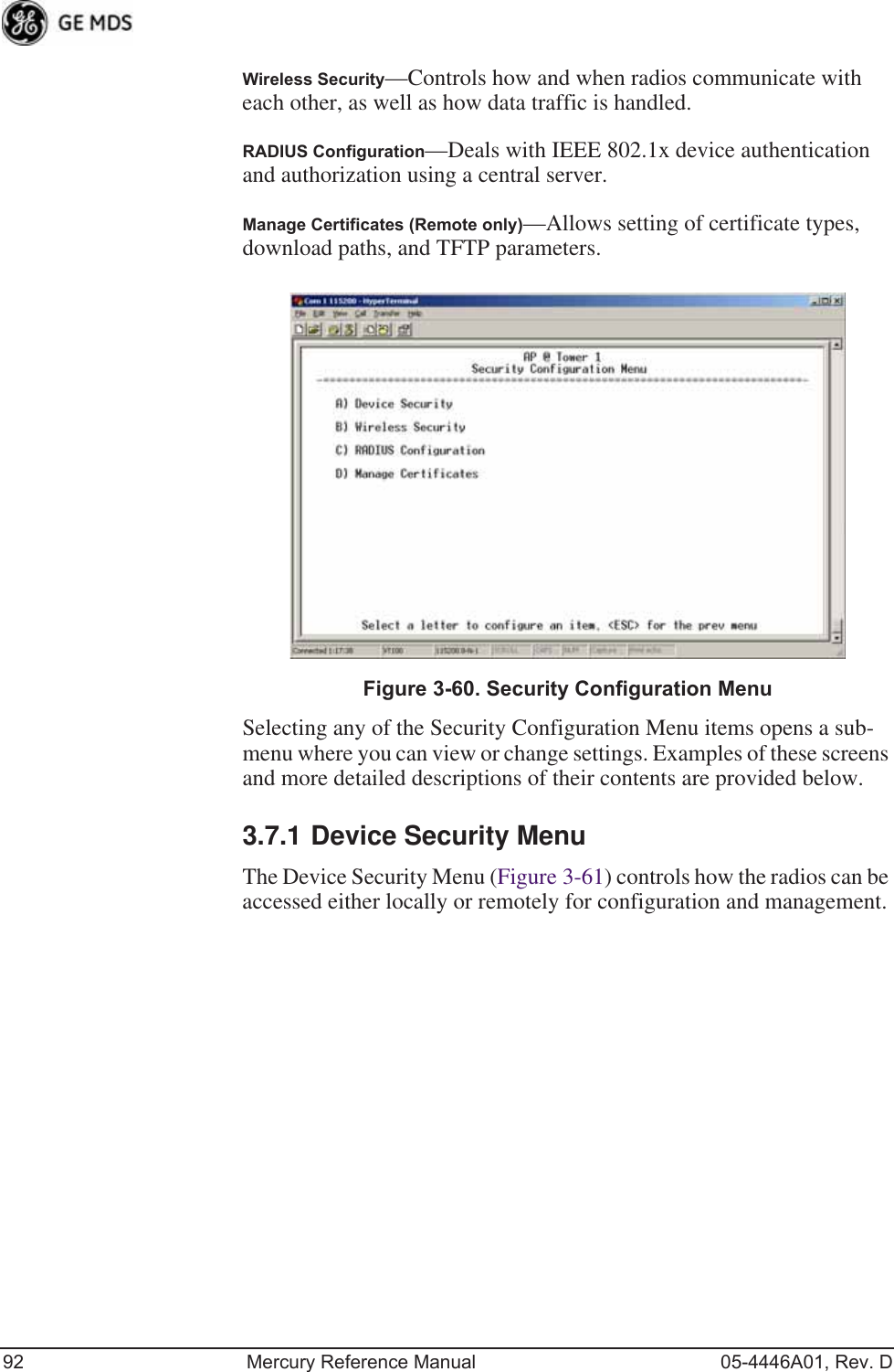
![05-4446A01, Rev. D Mercury Reference Manual 93Invisible place holderFigure 3-61. Device Security Menu•Telnet Access—Controls Telnet access to the transceiver’s man-agement system. [enabled, disabled; enabled]•SSH Access—Controls access to the Secure Shell (SSH) server.[enabled, disabled; enabled]•HTTP Mode—Controls access to the transceiver’s management system via the web server. [disabled, HTTP, HTTPS; HTTP]•HTTP Auth Mode—Selects the mode used for authenticating a web user. [Basic Auth, MD5 Digest; Basic Auth]•User Auth Method—View/set the method of authentication for users. [Local, Radius; Local]•User Auth Fallback—View/set method of authentication to use if the RADIUS server is unavailable. [None, Local; None] •User Passwords—Allows changing of Administrative and Guest passwords. When selected, a new screen appears (Figure 3-62 on Page 94).](https://usermanual.wiki/GE-MDS/DS-MERCURY900.Users-Manual-Revised-121908-Part-2/User-Guide-1048763-Page-27.png)
![94 Mercury Reference Manual 05-4446A01, Rev. DUser Passwords Menu Invisible place holderFigure 3-62. User Passwords MenuTo change the Administrator or Guest password, select the appropriate menu item (A or B). A flashing cursor appears to the right. From here, type the new password, which can be any alpha-numeric string up to 13 characters long. The change is asserted when you press the Return key.•Change Admin Password—Allows you to set a new password. [any alpha-numeric string up to 13 characters; admin]•Change Guest Password—Allows you to set a new password. [any alpha-numeric string up to 13 characters; guest]TIP: For enhanced security, consider using misspelled words, a combi-nation of letters and numbers, and a combination of upper and lower case letters. Also, the more characters used (up to 13), the more secure the password. These strategies help protect against sophisticated hackers who use a database of common words (for example, dictionary attacks) to determine a password.3.7.2 Wireless Security MenuThe features in the Wireless Security menu (Figure 3-63 on Page 95) control the communication of data across the wireless link. You can authenticate the radios locally via a list of authorized radios, or remotely via a centralized IEEE 802.1x device authentication server. This server provides a centralized authentication mechanism based on standards.](https://usermanual.wiki/GE-MDS/DS-MERCURY900.Users-Manual-Revised-121908-Part-2/User-Guide-1048763-Page-28.png)
![05-4446A01, Rev. D Mercury Reference Manual 95Invisible place holderFigure 3-63. Wireless Security Menu•Device Auth Mode—View/set the device’s authentication method. [None, Local, IEEE 802.1X; None]•Data Encryption—Controls the over-the-air payload data’s AES-128 bit encryption. [enable, disable; disabled]•Encryption Phrase—View/set the phrase used to generate encryp-tion keys when encrypting over-the-air payload. [any alpha-numeric string of 8 to 15 characters; <empty>]•Max Remotes (AP only)—The maximum number of remotes an AP can associate with.•Approved Remotes (AP only)—Launches a submenu where you can view, add, or delete approved Remotes. (See Figure 3-64.)Approved Remotes Submenu Setting the Device Auth Mode to Local forces an AP to check the Approved Remotes List before establishing a radio link. A Remote must be in the list before the AP associates and grants authorization. Before enabling this option, at least one entry must already exist in the View Approved Remotes list.](https://usermanual.wiki/GE-MDS/DS-MERCURY900.Users-Manual-Revised-121908-Part-2/User-Guide-1048763-Page-29.png)
![96 Mercury Reference Manual 05-4446A01, Rev. DInvisible place holderFigure 3-64. Approved Remotes Submenu•Add Remote—Enter the MAC address of Remote.[Any valid 6-digit hexadecimal MAC address; 00:00:00:00:00:00] •Delete Remote—Enter the MAC address of Remote. For security purposes, you should delete a stolen or deprovisioned radio from this list.•Add Associated Remotes—Add all currently associated remotes to the approved remote list. Alternatively, you can enter each Remote MAC manually.•Delete All Remotes—Remove (complete purge) all Remotes from current list.•View Approved Remotes—Listing of approved Remotes by MAC address. These radios are authorized to join this AP. If a Remote is not in this list, it cannot associate with this AP.3.7.3 IEEE 802.1x Device AuthenticationThis section covers the configuration needed for the radios to access the IEEE 802.1x device authentication server, which provides Device Level Security and for Wireless Access Security. GE MDS does not provide the server software.Operation of Device AuthenticationDevice authentication forces the radio to authenticate before allowing user traffic to traverse the wireless network. When Device Security is configured to use IEEE 802.1x as the Authentication Method, Remote radios need three types of certificates: public (client), private, and root (Certificate Authority). These files are unique to each Remote radio and must first be created at the server and then installed into each unit via TFTP. The certificate files must be in DER format.Device authentication uses the serial number of each radio as the Common Name (CN) in its certificate and in its RADIUS identity field.](https://usermanual.wiki/GE-MDS/DS-MERCURY900.Users-Manual-Revised-121908-Part-2/User-Guide-1048763-Page-30.png)
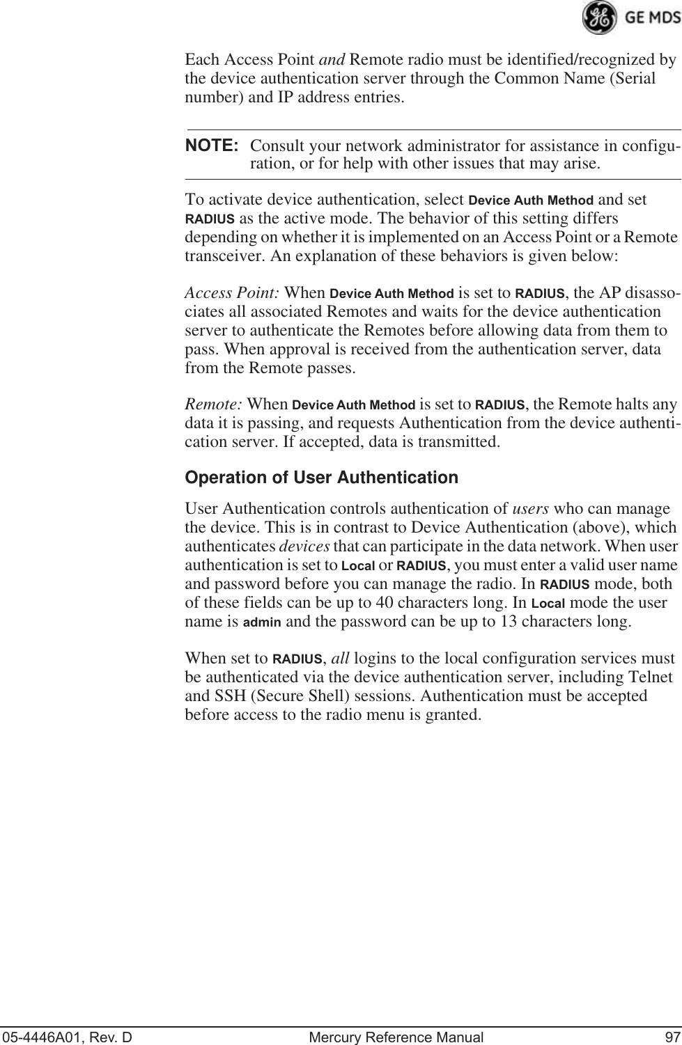
![98 Mercury Reference Manual 05-4446A01, Rev. DRADIUS Configuration Menu Invisible place holderFigure 3-65. Radius Configuration Menu•Auth Server Address—The IP address of the authentication server. [any valid IP address; 0.0.0.0]•Auth Server Port—The UDP Port of the authentication server. [1812, 1645, 1812]•Auth Server Shared Secret—User authentication and Device authentication require a common shared secret to complete an authentication transaction. This entry must match the string used to configure the appropriate files on the authentication server. [<empty>; any alpha-numeric string up to 16 characters]•User Auth Mode—RADIUS Authentication algorithm.[PAP, CHAP, EAP; PAP]NOTE: CHAP is a more secure algorithm than PAP. PAP may displaythe login password in log files at the authentication serverwhile CHAP will encrypt this information.3.7.4 Manage CertificatesUse Certificate generation software to generate certificate files, then install these files into each Remote unit using TFTP. This is done using the Manage Certificates Menu (Figure 3-66 on Page 99). The certificate files must be in DER format. The Common Name (CN) field in the public certificate file must match the serial number of the unit it is installed on.](https://usermanual.wiki/GE-MDS/DS-MERCURY900.Users-Manual-Revised-121908-Part-2/User-Guide-1048763-Page-32.png)
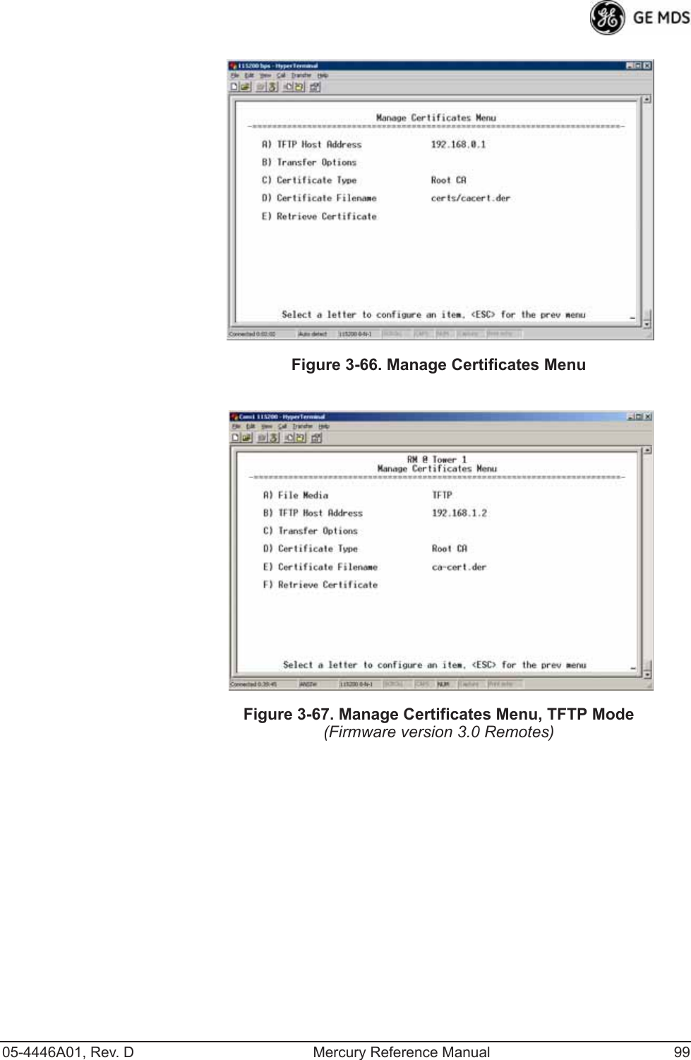
![100 Mercury Reference Manual 05-4446A01, Rev. DInvisible place holderFigure 3-68. Manage Certificates Menu, USB Mode(Firmware version 3.0 Remotes)•File Media—A selection of methods for transferring files to and from the radio. On firmware version 3.0 radios, the options are TFTP and USB.•TFTP Host Address—(Telnet/Terminal only)—IP address of the com-puter on which the TFTP server resides. This same IP address is used in other screens/functions (reprogramming, logging, etc.). Changing it here also changes it for other screens/functions.[Any valid IP address; 127.0.0.1].•Transfer Options—A menu for configuring the TFTP transfer. (See Figure 3-69 on Page 101.)Three certificate files (Root CA, Client, and Private Key) must be present in each of the Remote radios. Use the commands described below to install these files into each Remote radio:•Certificate Type—Selects one of the three certificate file types mentioned above. [Root CA, Client, Private Key; Root CA]•Certificate Filename—Specifies the software path and filename for downloading certificates.•Retrieve Certificate—Initiates the retrieval of the certificate file from the storage location. A successful installation issues a Com-plete status message.NOTE: It is imperative that the three certificate files are installedcorrectly into the Remote radio, in their respective file types.If they are not, the Remote is un-authenticated for data traffic.Consult your network administrator for more information.](https://usermanual.wiki/GE-MDS/DS-MERCURY900.Users-Manual-Revised-121908-Part-2/User-Guide-1048763-Page-34.png)
![102 Mercury Reference Manual 05-4446A01, Rev. DInvisible place holderFigure 3-70. Redundancy Configuration Menu (AP Only)•Redundancy Configuration—Enable/disable redundancy switcho-ver for AP. [enabled, disabled; disabled]•Network Event Triggers—This selection opens a submenu (Figure 3-71 on Page 103) where you can set/view the trigger status for Network Events.•Radio Event Triggers—This selection opens a submenu (Figure 3-72 on Page 103) where you can set/view the trigger status for Radio Events, such as a loss of associated Remotes or excessive packet errors.•Hardware Event Triggers—This selection opens a submenu (Figure 3-73 on Page 104) where you can set/view the trigger status for initialization/hardware errors.•Redundancy Configuration Options—This selection opens a sub-menu (Figure 3-74 on Page 104) where you can set the thresh-old criteria for declaring an error event.•Force Switchover—Selecting this option forces a manual (user initiated) switchover to the backup AP. The “challenge ques-tion” Are you sure? (y/n) is presented to avoid an unintended switchover. To invoke the change, press the letter y followed by the Enter key.](https://usermanual.wiki/GE-MDS/DS-MERCURY900.Users-Manual-Revised-121908-Part-2/User-Guide-1048763-Page-36.png)
![05-4446A01, Rev. D Mercury Reference Manual 103Network Event Triggers Menu Invisible place holderFigure 3-71. Network Events Triggers Menu•Network Interface Error—This setting determines whether or not a network interface error will cause redundancy switchover. [enabled, disabled; disabled]Radio Event Triggers Invisible place holderFigure 3-72. Radio Event Triggers•Lack of associated remotes exceeded threshold—This setting deter-mines whether or not a switchover occurs when a lack of asso-ciated Remote units exceeds the time period set in Figure 3-75 on Page 105. [enabled, disabled; disabled]•Packet Receive Errors exceeded threshold—This setting determines whether or not a switchover occurs when the number of Packet Receive errors exceeds the number set in Figure 3-76 on Page 105. [enabled, disabled; disabled]](https://usermanual.wiki/GE-MDS/DS-MERCURY900.Users-Manual-Revised-121908-Part-2/User-Guide-1048763-Page-37.png)
![104 Mercury Reference Manual 05-4446A01, Rev. DHardware Event Triggers Invisible place holderFigure 3-73. Hardware Event Triggers•Init/Hardware Error—This setting determines whether or not an initialization or hardware error results in a redundancy switcho-ver. [enabled, disabled; disabled]Redundancy Configuration Options MenuUse this menu (Figure 3-74) to set the thresholds for the Lack of Asso-ciated Remotes and Packet Receive Errors. Selecting either item opens a submenu where you can view or change settings.Invisible place holderFigure 3-74. Redundancy Configuration Options Menu•Lack of Associated Remotes Exceeded Threshold—This selection opens a submenu (Figure 3-75) where you can view or change the time period allowed for a lack of associated Remotes.](https://usermanual.wiki/GE-MDS/DS-MERCURY900.Users-Manual-Revised-121908-Part-2/User-Guide-1048763-Page-38.png)
![05-4446A01, Rev. D Mercury Reference Manual 105•Packet Receive Errors Exceeded Threshold—This selection opens a submenu (Figure 3-76 on Page 105) where you can view or change the maximum allowable number of receive errors.Lack of Associated Remotes Exceeded Threshold MenuInvisible place holderFigure 3-75. Lack of Associated Remotes Exceeded Threshold Menu•Lack of Remotes for—Select this item to change the time setting (in seconds) for a lack of associated Remotes. When there are no associated Remotes for a period exceeding this time, a redun-dancy switchover occurs. [60-500; 500]Packet Receive Errors Exceeded Threshold MenuInvisible place holderFigure 3-76. Packet Receive Errors Exceeded Threshold Menu•Maximum Receive Errors—Select this item to change the maxi-mum allowable number of receive errors. When the number of errors exceeds this number, a redundancy switchover occurs. [0-1000; 500]](https://usermanual.wiki/GE-MDS/DS-MERCURY900.Users-Manual-Revised-121908-Part-2/User-Guide-1048763-Page-39.png)
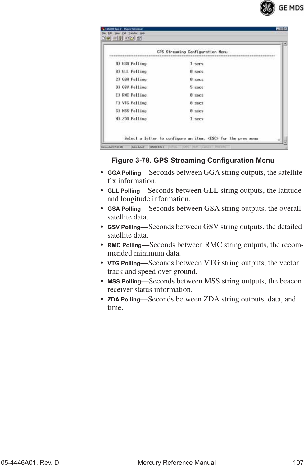
![106 Mercury Reference Manual 05-4446A01, Rev. D3.9 GPS CONFIGURATION (REMOTE ONLY)This menu allows you to view or set important parameters for the built-in Global Positioning System (GPS) receiver in the Mercury Remote. Mercury 3650 Remote units do not have or require GPS func-tionality. Details about the NMEA sentences generated by the GE MDS Mercury can be found at http://www.nps.gov/gis/gps/NMEA_sentences.html. Invisible place holderFigure 3-77. GPS Configuration Menu (Remote Only)•Stream GPS to Console—Used to enable/disable streaming of GPS NMEA data to the console port (COM1). Baud rate is 4800 baud when Stream GPS to console is enabled.[enabled, disabled; disabled]•GPS to Console Baud Rate—The serial baud rate when GPS streaming is enabled.•Send GPS via UDP—Used to enable/disable sending GPS NMEA data to a server via UDP. [enabled, disabled; disabled]•GPS UDP Server IP Address—Specify the destination address for GPS NMEA UDP packets. [any valid IP address; 0.0.0.0]•GPS UDP Server UDP Port—Destination UDP port for GPS NMEA UDP packets. [valid UDP port number; 0]•GPS Streaming Configuration—A submenu for setting GPS NMEA outputs. (See Figure 3-78 on Page 107.)](https://usermanual.wiki/GE-MDS/DS-MERCURY900.Users-Manual-Revised-121908-Part-2/User-Guide-1048763-Page-40.png)
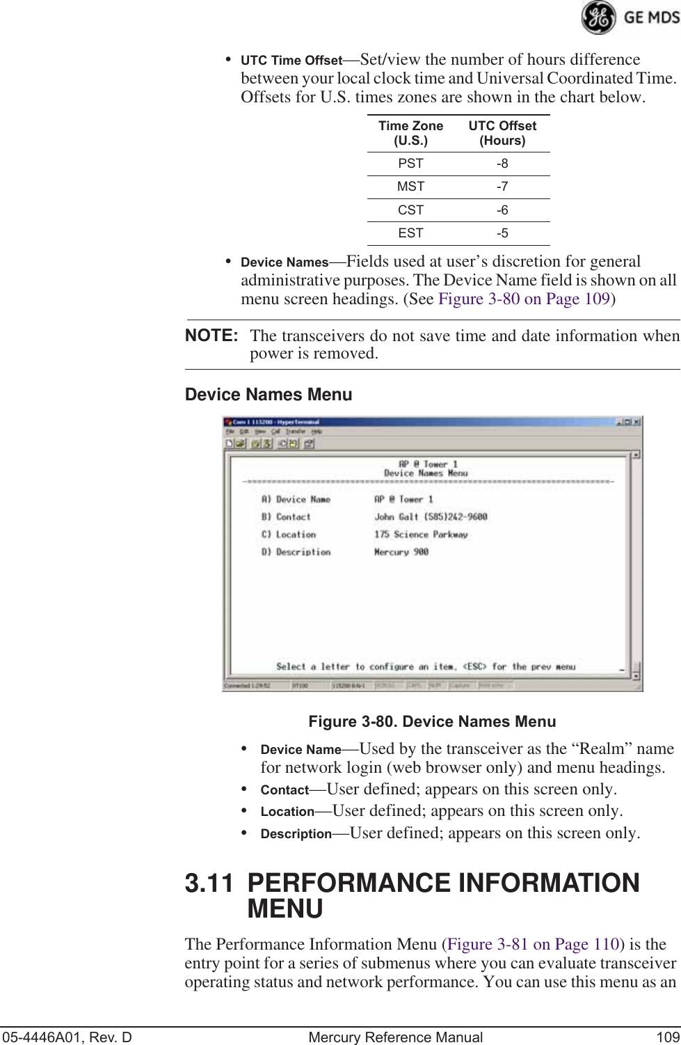
![108 Mercury Reference Manual 05-4446A01, Rev. D3.10 DEVICE INFORMATION MENUFigure 3-79 shows the menu that displays basic administrative data on the unit to which you are connected. It also provides access to user-spe-cific parameters such as date/time settings and device names.Figure 3-79. Device Information Menu•Model (Display only)•Serial Number (Display only)•Uptime (Display only)—Elapsed time since boot-up.•Date—Current date being used for the transceiver logs. User-set-able. (Value lost with power failure if SNTP [Simple Network Time Protocol] server not accessible.) •Time—Current time of day. User-setable. Setting: HH:MM:SS (Value lost with power failure if SNTP server not accessible.)•Date Format—Select presentation format:• Generic = dd Mmm yyyy• European = dd-mm-yyyy• US = mm-dd-yyyy•Console Baud Rate—Used to set/display data communications rate (in bits-per-second) between a connected console terminal and the radio. [115200]](https://usermanual.wiki/GE-MDS/DS-MERCURY900.Users-Manual-Revised-121908-Part-2/User-Guide-1048763-Page-42.png)
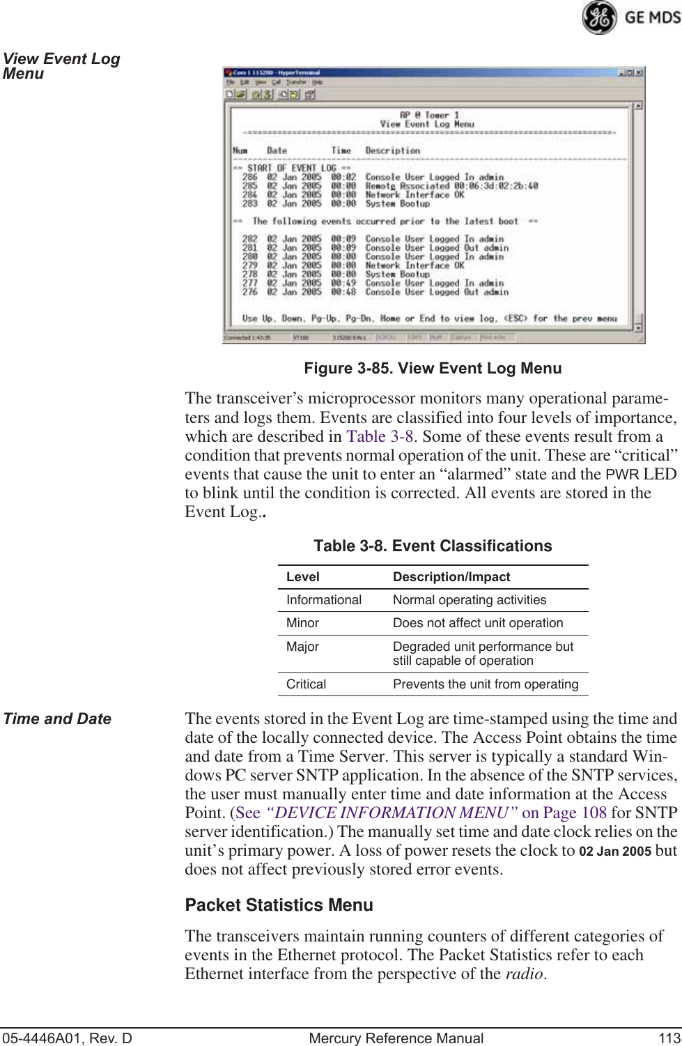
![112 Mercury Reference Manual 05-4446A01, Rev. DEvent Log Menu Invisible place holderFigure 3-84. Event Log Menu•Current Alarms—Shows active alarms (if any) reported by the transceiver.•View Event Log—Displays a log of radio events arranged by event number, date, and time. (Example shown in Figure 3-85 on Page 113).•Clear Event Log—Erases all previously logged events.•Send Event Log—Sends the event log to the server. You must answer the challenge question Send File? y/n before the request proceeds.•Event Log Host Address—Set/display the IP address of the TFTP server. [any valid IP address; 0.0.0.0]•Event Log Filename—Set/display the name of the event log file on the TFTP server. [any valid filename; eventlog.txt]•Transfer Options—A menu for configuring the TFTP transfer.•Syslog Server Address—Use this selection to set or view the IP address of the Syslog server. Syslog is a standardized protocol for sending IP log data across a network. Low cost (or even free) Syslog downloads are available online by searching for the term “Syslog Server.” [any valid IP address; 0.0.0.0]](https://usermanual.wiki/GE-MDS/DS-MERCURY900.Users-Manual-Revised-121908-Part-2/User-Guide-1048763-Page-46.png)
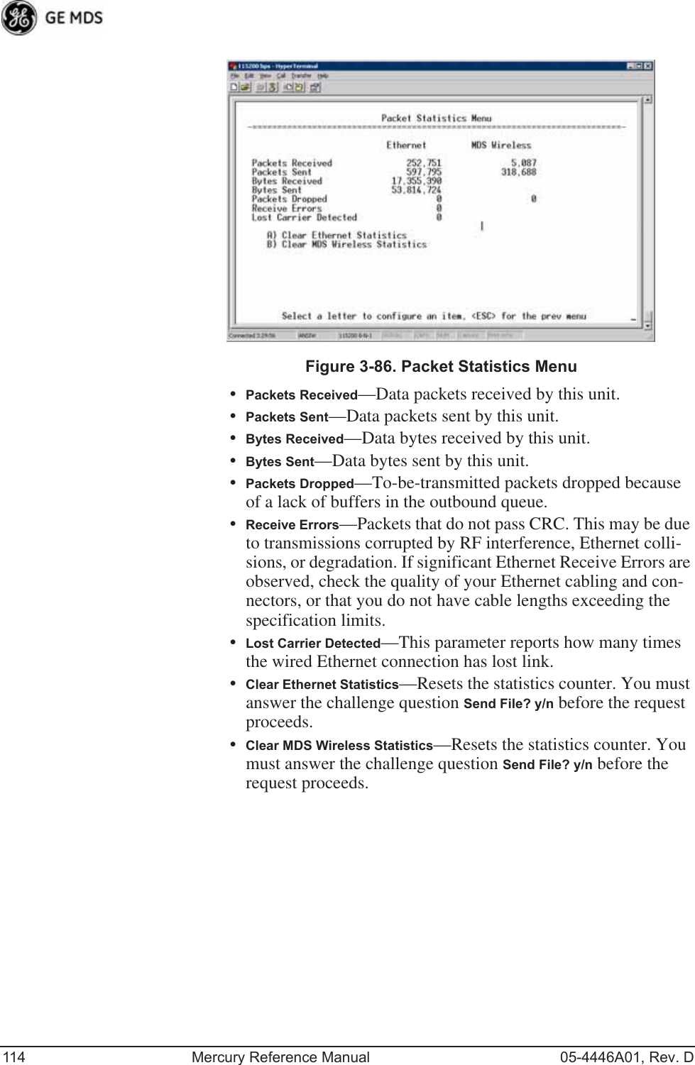
![05-4446A01, Rev. D Mercury Reference Manual 115GPS Status Menu Invisible place holderFigure 3-87. GPS Status Menu•GPS Serial Number—The serial number of the GPS unit in the radio.•GPS Firmware Version—The firmware version running on the GPS chip.•Satellite Fix Status—Indicates whether or not the unit has achieved signal lock with the minimum required number of GPS satellites. The transceiver requires a fix on five satellites to achieve Precise Positioning Service (PPS) and four to maintain PPS. [No Fix, Fix]•Number of Satellites—Shows the number of GPS satellites received by the transceiver. Although there are typically 24 active GPS satellites orbiting the Earth twice a day, only a sub-set of these is “visible” to a receiver at a given location. A good signal provides information from six to ten satellites.•Latitude—Shows the transceiver’s latitudinal location (in degrees), based on GPS data received from the satellites.•Longitude—Shows the transceiver’s longitudinal location (in degrees), based on GPS data received from the satellites.•Altitude—Shows the transceiver’s altitude above sea level (in feet), based on GPS data received from the satellites.•GPS Information—Shows data about the individual satellites being received, including the Pseudo-Random Noise (PRN) code (a unique bit stream for each satellite), the satellite’s ele-vation (in degrees), azimuth (in degrees), and the sig-nal-to-noise ratio of the carrier signal (SNR). Figure 3-88 on Page 116 shows a layout example for this screen.](https://usermanual.wiki/GE-MDS/DS-MERCURY900.Users-Manual-Revised-121908-Part-2/User-Guide-1048763-Page-49.png)
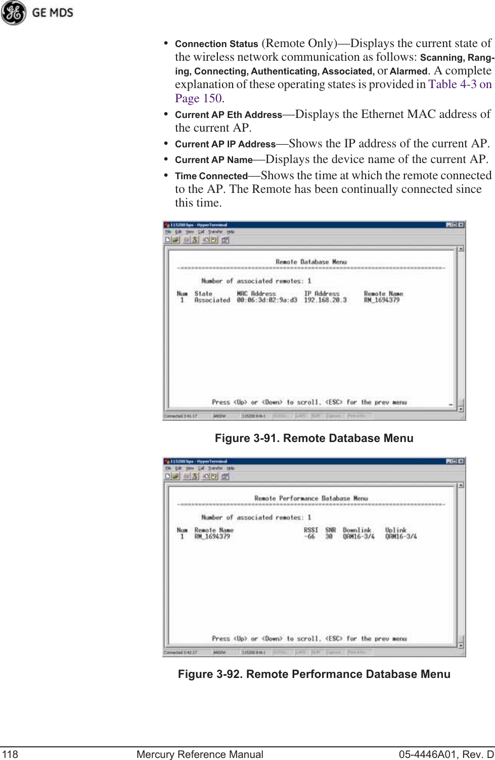
![05-4446A01, Rev. D Mercury Reference Manual 117Invisible place holderFigure 3-89. Wireless Network Status Menu (AP)Invisible place holderFigure 3-90. Wireless Network Status Menu (Remote)•Device Status—Displays the overall operating condition of the transceiver. [Operational, Alarmed]•Associated Remotes (AP Only)—Shows the number of Remote transceivers currently associated with the AP.•Remote Database (AP Only)—Displays a submenu where associ-ated Remotes are listed in table form according to their number, operational state, MAC address, IP address, and name (if assigned). (See Figure 3-91 on Page 118.)•Remote Performance Database (AP Only)—Displays a submenu where associated Remote performance data is listed in table form. Remotes are presented according to their number, MAC address, RSSI, SNR, modulation type, and FEC total. (See Figure 3-92 on Page 118.)](https://usermanual.wiki/GE-MDS/DS-MERCURY900.Users-Manual-Revised-121908-Part-2/User-Guide-1048763-Page-51.png)
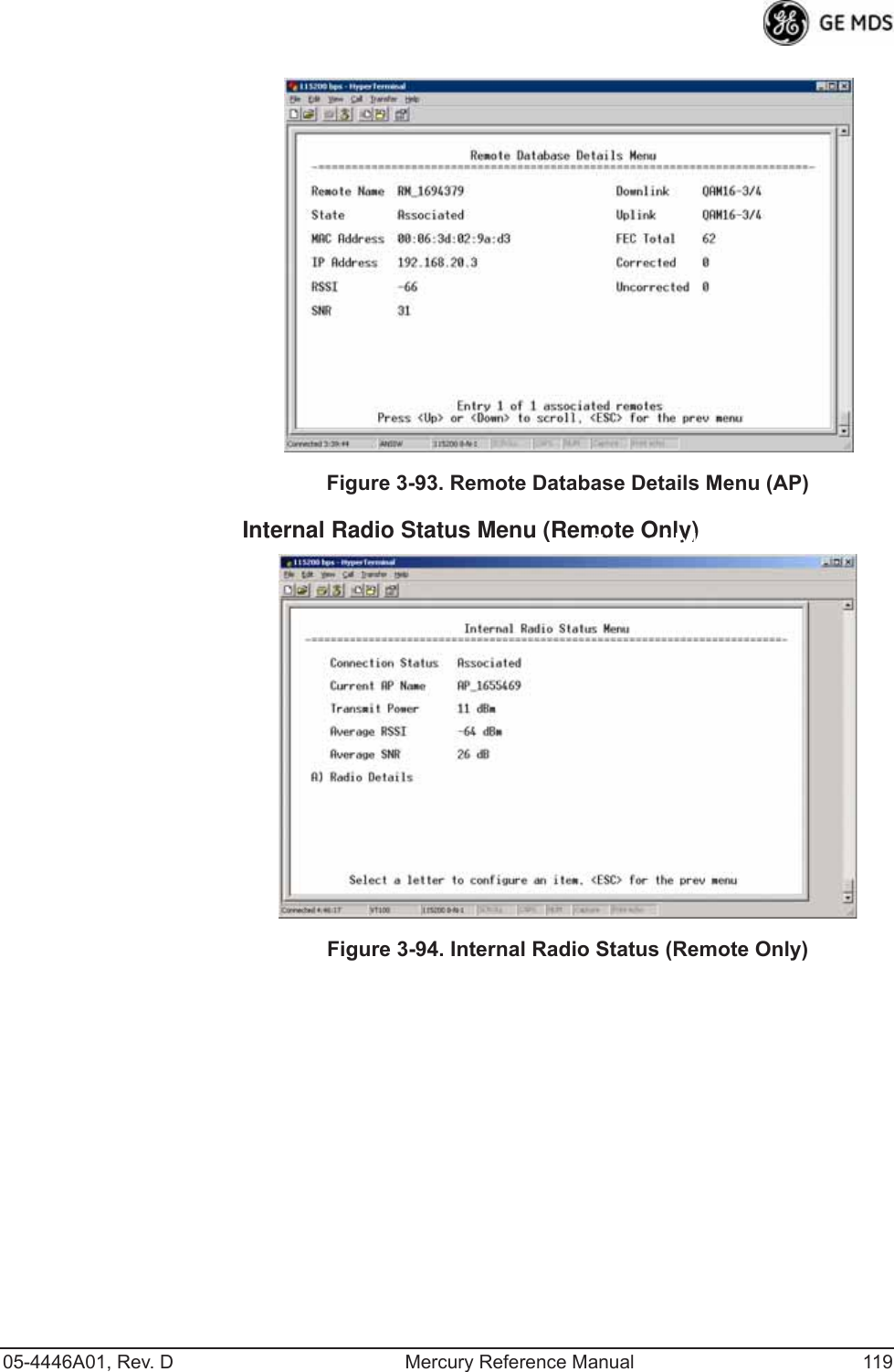
![120 Mercury Reference Manual 05-4446A01, Rev. DInvisible place holderFigure 3-95. Internal Status Menu(Remote in Static Hopping mode)Invisible place holderFigure 3-96. Internal Radio Status Menu(Remote in Hopping with Handoffs Mode)NOTE: In the menu above, the items in the right hand column aredisplayed on Remotes only, when they are in Hopping withHandoffs mode. This allows viewing of the settings theRemote is using to connect to each AP in the AP LocationsFile. See Frequency Control Menu on Page 65 for explanationsof these items. Exception: The Scanning Timer parameter isunique to the screen shown in Figure 3-96, and is explainedbelow.•Connection Status—Indicates whether or not the Remote station has associated with an AP. [Associated, Scanning, Ranging, Connecting, Authorizing]•Current AP Name—Shows the Device Name of the current AP.](https://usermanual.wiki/GE-MDS/DS-MERCURY900.Users-Manual-Revised-121908-Part-2/User-Guide-1048763-Page-54.png)
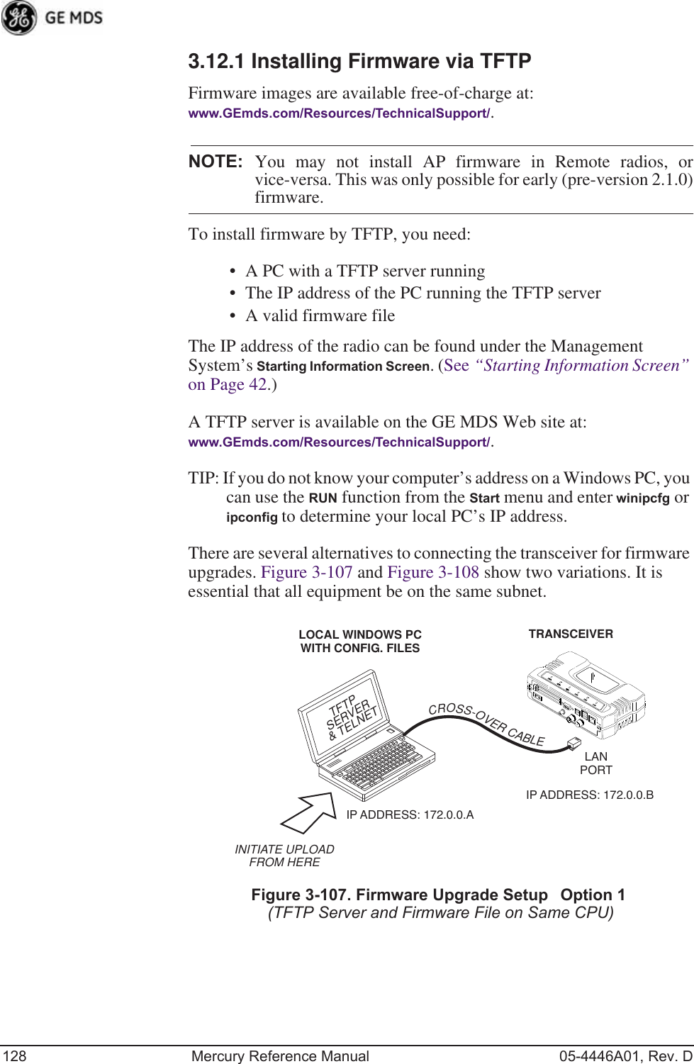
![126 Mercury Reference Manual 05-4446A01, Rev. DInvisible place holderFigure 3-104. Reprogramming Menu(Firmware 3.0 Remote Only, TFTP Mode)Invisible place holderFigure 3-105. Reprogramming Menu(Firmware 3.0 Remote Only, USB Mode)•File Media—A selection of methods for transferring files to and from the radio. On firmware version 3.0 radios, the options are TFTP and USB.•TFTP Host Address—IP address of the host computer from which to get the file. [Any valid IP address] This same IP address is used in other screens/functions (reprogramming, logging, etc.). Changing it here also changes it for other screens/functions.•Firmware Filename—Name of file to be received by the TFTP server. [Any 40-character alphanumeric string] Verify that this cor-responds to the TFTP directory location. May require sub-direc-tory, for example: me-bkrc-2_1_0.mpk.•Transfer Options—A menu for configuring the TFTP transfer.](https://usermanual.wiki/GE-MDS/DS-MERCURY900.Users-Manual-Revised-121908-Part-2/User-Guide-1048763-Page-60.png)
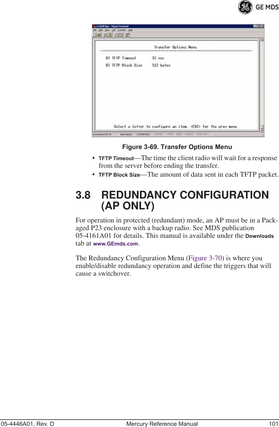
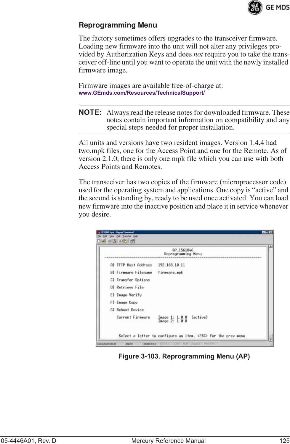
![05-4446A01, Rev. D Mercury Reference Manual 127•Retrieve File—Initiates the file transfer from the TFTP server. The new file is placed into inactive firmware image. [Y, N ]•Image Verify—Initiate the verification of the integrity of firm-ware file held in unit.•Image Copy—Initiate the copying of the active firmware into the inactive image.•Reboot Device—Initiates rebooting of the transceiver. This will interrupt data traffic through this unit, and the network if per-formed on an Access Point. Intended to be used for switching between firmware images 1 and 2.•Advanced ReprogrammingAdvanced configuration options for TFTP transfer of firmware files. See Figure 3-106 and related text descriptions.•Current Firmware—Displays the versions of firmware images installed in the transceiver and shows whether Image 1 or Image 2 is currently active.NOTE: See Upgrade Procedure on Page 129 for details on setting upthe TFTP server.Invisible place holderFigure 3-106. Advanced Reprogramming Menu•TFTP Timeout—View/set the time (in seconds) where no activity results in a TFTP timeout condition.•TFTP Block Size—The data size of each TFTP block being trans-ferred to the radio during firmware upgrade.•Image Verify—Initiate the verification of the integrity of firm-ware file held in unit.•Image Copy—Initiate the copying of the active firmware into the inactive image.•Firmware Versions—Shows the available versions of firmware code for operation of the radio.](https://usermanual.wiki/GE-MDS/DS-MERCURY900.Users-Manual-Revised-121908-Part-2/User-Guide-1048763-Page-61.png)
![132 Mercury Reference Manual 05-4446A01, Rev. DInvisible place holderFigure 3-110. Configuration Scripts Menu(Firmware 3.0 Remote Only, TFTP mode)Invisible place holderFigure 3-111. Configuration Scripts Menu(Firmware 3.0 Remote Only, USB mode)•File Media—A selection of methods for transferring files to and from the radio. On firmware version 3.0 radios, the options are TFTP and USB.•Config Filename—Name of file containing this unit’s configura-tion profile that will be transferred to the TFTP server. The con-figuration information is in plain-text ASCII format.[Any 40-character alphanumeric string] May require a sub-direc-tory, for example: config\mercury-config.txt. (See “Configuration Scripts Menu” on Page 130 for more information.)](https://usermanual.wiki/GE-MDS/DS-MERCURY900.Users-Manual-Revised-121908-Part-2/User-Guide-1048763-Page-66.png)
![05-4446A01, Rev. D Mercury Reference Manual 133NOTE: The filename field is used to identify the desired incoming fileand as the name of the file exported to the TFTP server. Beforeexporting a unit’s configuration, name it in a way that reflectsthe radio’s services or other identification.•TFTP Host Address—IP address of the computer on which the TFTP server resides. [Any valid IP address]•Transfer Options—A menu for configuring the TFTP transfer.•Category—The category of parameters to send or receive.•Retrieve File—Initiate the file transfer of the configuration file from TFTP server into the transceiver.•Send File—Initiate the file transfer from the transceiver’s current configuration file to TFTP server.NOTE: See “Upgrade Procedure” on Page 129 for details on settingup the TFTP server.Sample of Configuration Script FileA sample configuration script file is provided as part of every firmware release. Firmware images and sample files are available free-of-charge at: www.GEmds.com/Resources/TechnicalSupport/.The name of the specific file includes the firmware revision number, represented by the “x” characters in the following example: mercury-config-x_x_x.txt. Editing Configuration FilesOnce a Remote unit’s operation is fine-tuned, use the Configuration Scripts Menu on Page 130 to save a copy of the configuration onto a PC. Once the file is saved on the PC, you can use it as a source to generate modified copies adjusted to match other devices. Modify the configura-tion files using a text editor or an automated process. (These applica-tions are not provided by GE MDS).We recommend that you review and update the following parameters for each individual unit. Change other parameters as necessary. Save each resulting file with a different name. We recommend using directories and file names that reflect the location of the unit to facilitate later iden-tification.Table 3-10. Common User-Alterable Parameters Field Comment RangeIP Address Unique for each individual radio. Any legal IP addressIP Gateway May change for different groups or locations.Any legal IP address](https://usermanual.wiki/GE-MDS/DS-MERCURY900.Users-Manual-Revised-121908-Part-2/User-Guide-1048763-Page-67.png)
![134 Mercury Reference Manual 05-4446A01, Rev. DEditing Rules • Only include parameters you want to change from the default value.• Change only the parameter values.• Capitalization counts in some field parameters. • Comment Fields:a. Edit or delete anything on each line to the right of the comment delineator, the semicolon (;).b. Comments can be of any length, but must be on the same line as the parameter, or on a new line that begins with a semicolon character.c. Comments after parameters in files exported from a trans-ceiver do not need to be present in your customized files.• Some fields are read-only. These are designated by “(RO)” in the configuration sample file.Ping Utility Menu Invisible place holderFigure 3-112. Ping Utility Menu•Address to Ping—Address to send a Ping. [Any valid IP address]•Count—Number of Ping packets to be sent.•Packet Size—Size of each Ping data packet (bytes).Device Name Should reflect a specific device. This information will appear in Management System headings.Any 20-character alphanumeric stringLocation Used only as reference for network administration. Any 40-character alphanumeric stringTable 3-10. Common User-Alterable Parameters (Continued)Field Comment Range](https://usermanual.wiki/GE-MDS/DS-MERCURY900.Users-Manual-Revised-121908-Part-2/User-Guide-1048763-Page-68.png)
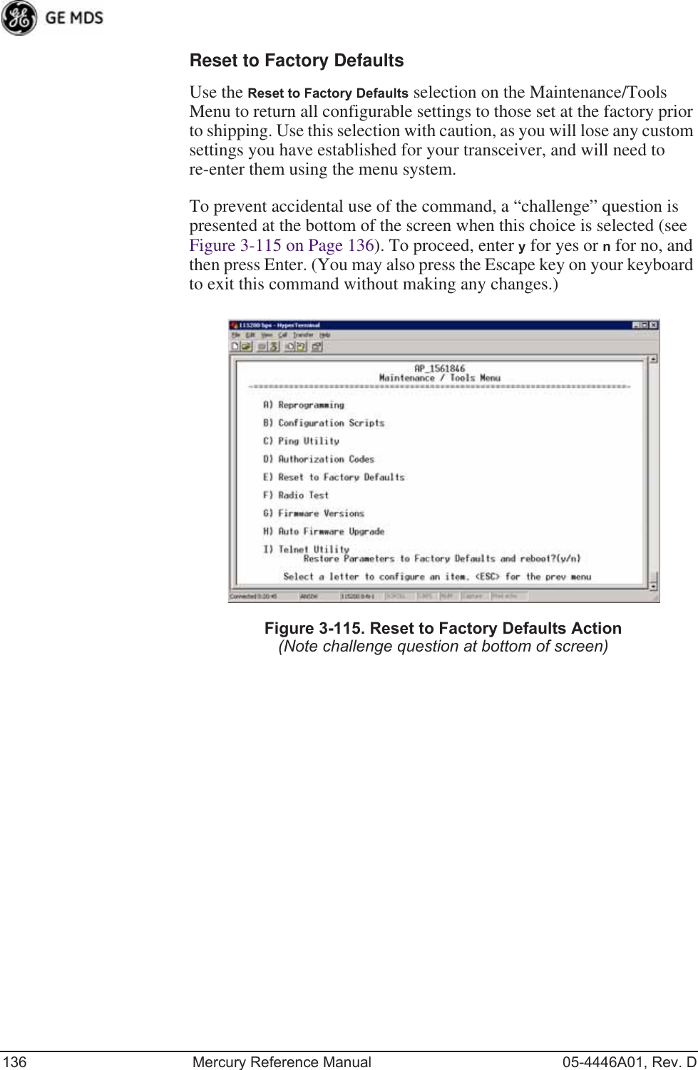
![138 Mercury Reference Manual 05-4446A01, Rev. DInvisible place holderFigure 3-117. Radio Test MenuNOTE :Using Test Mode disrupts traffic through the radio. If the unitis an Access Point, it will disrupt traffic through the entirenetwork. The Test Mode function is automatically limited to10 minutes. Only use Test Mode for brief measurements.•Radio Mode—Sets/displays the radio’s operating mode. To change the setting, press A on the PC’s keyboard and press the Spacebar to toggle between the two settings. Press the Enter key to select the desired state. [Normal, Test; Normal]•Test Status—This read-only parameter shows the current state of the radio. [Radio is Operational, Reconfiguring the Radio, Ready to KEY]The following parameters are read-only unless A) Radio Mode is first selected and set to Test. In Test Mode, these items become selectable, and you can set their entries using the Spacebar or with a numeric entry, followed by pressing the Enter key.•Test Key—Sets/displays keying status of the radio’s transmitter. Use the Spacebar to view selections. [disabled, enabled; disabled]•Test Transmit Power—Sets/displays the transmitter’s power set-ting. Make a numerical entry within the allowable range. [3650 model: +23 dBm max][900 model: -30 to +29 dBm]•Test Channel—Sets/displays the radio’s test channel number. Make a numerical entry within the allowable range.[0-13; 0]•Test RF Bandwidth—Sets/displays the transmitter’s bandwidth for testing. Use the Spacebar to view selections.[1.75. 3.5 MHz; 1.75 MHz—additional selections for 3650 model]•Test Burst Percentage—Sets/displays the percentage of Burst size to use for testing. Make a numerical entry within the allowable range. [0-100%; 100]](https://usermanual.wiki/GE-MDS/DS-MERCURY900.Users-Manual-Revised-121908-Part-2/User-Guide-1048763-Page-72.png)