GE MDS DS-MERCURY3650 Wireless IP/Ethernet Transceiver User Manual Book1
GE MDS LLC Wireless IP/Ethernet Transceiver Book1
GE MDS >
Contents
- 1. User manual
- 2. Revised user manual 1 of 3
- 3. Revised user manual 2 of 3
- 4. Revised user manual 3 of 3
Revised user manual 3 of 3
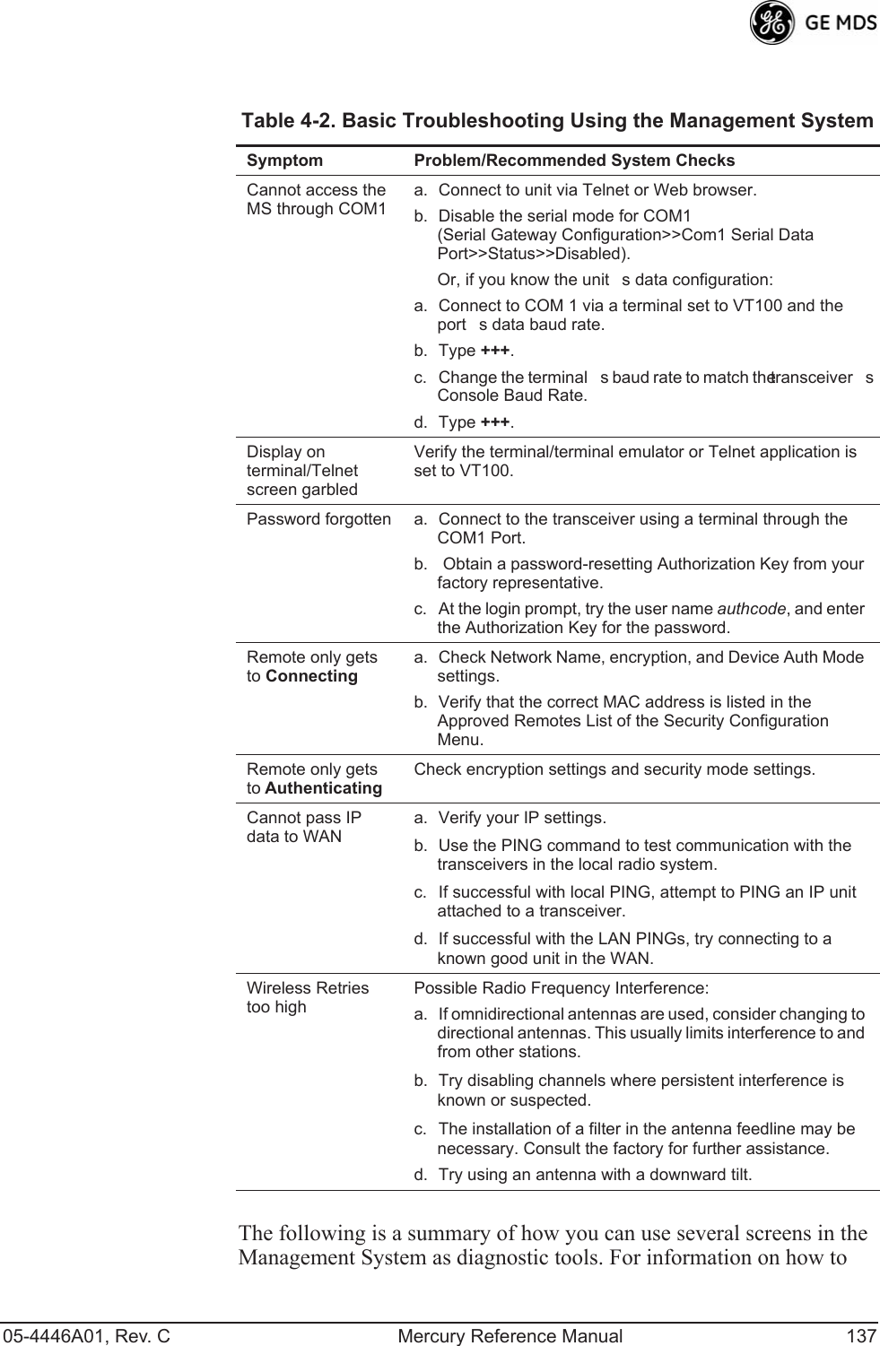
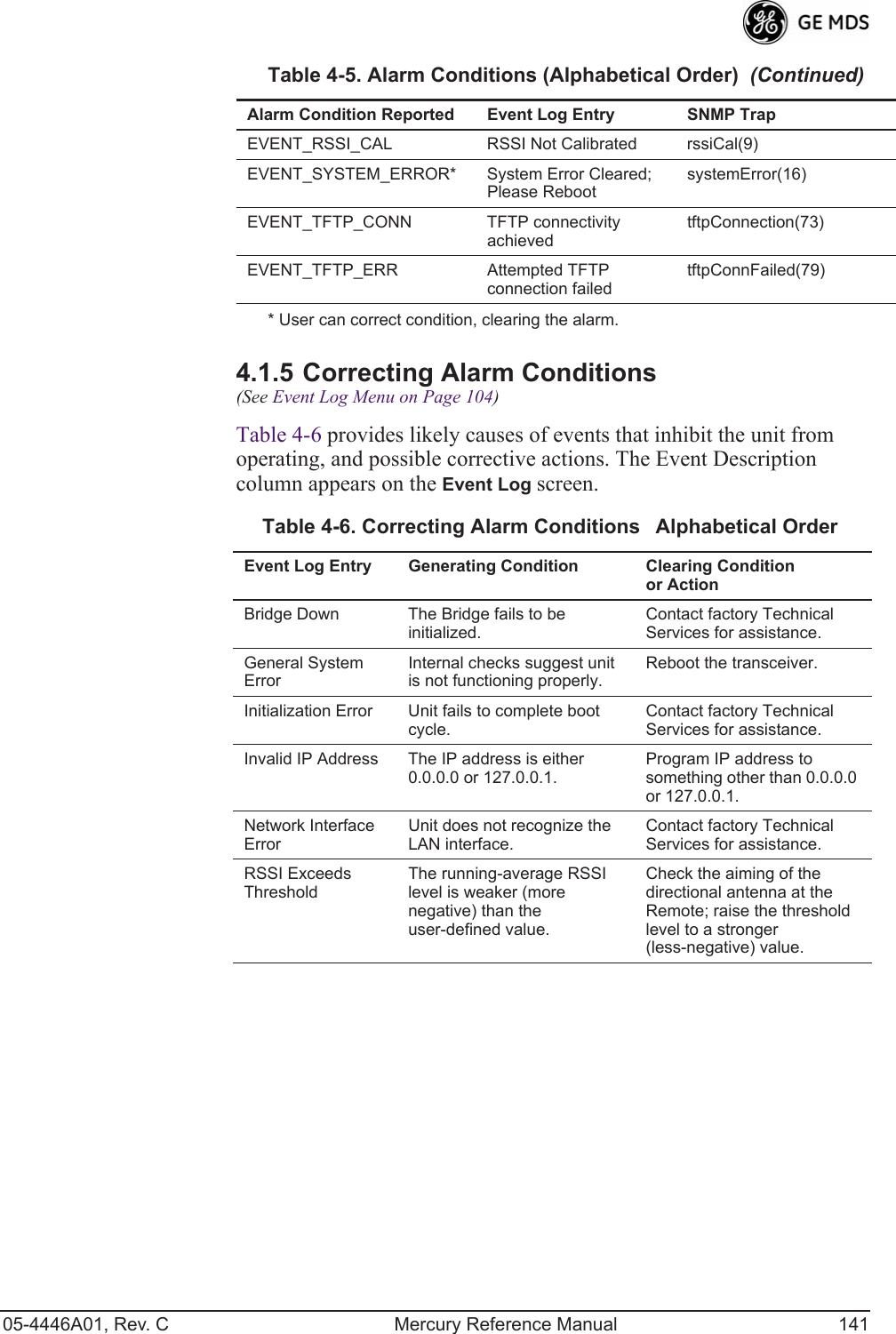
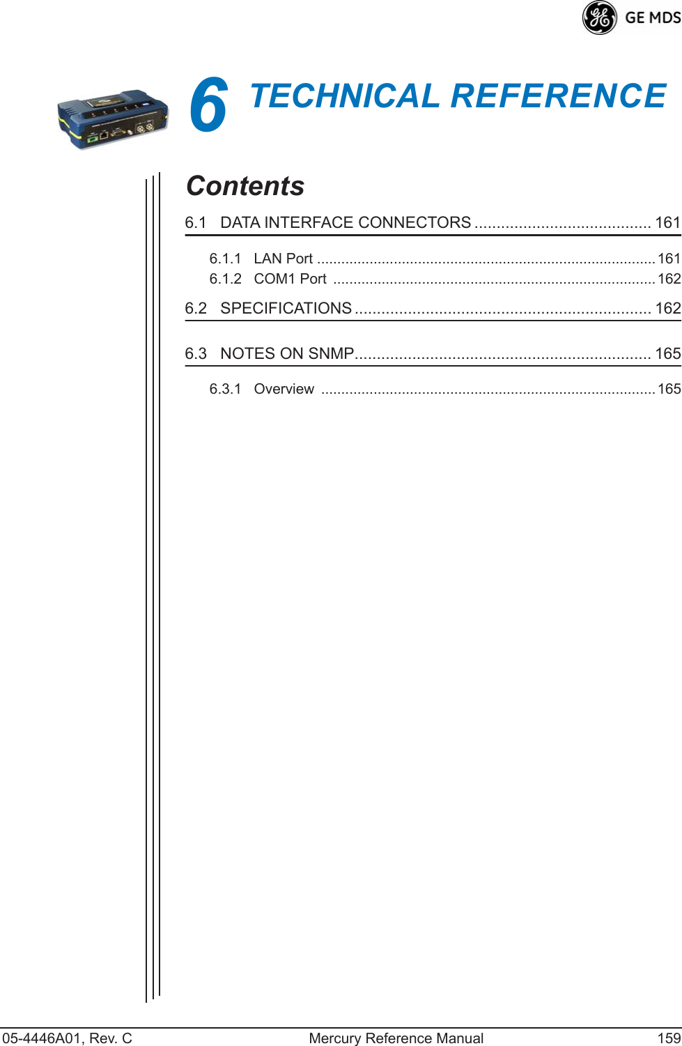
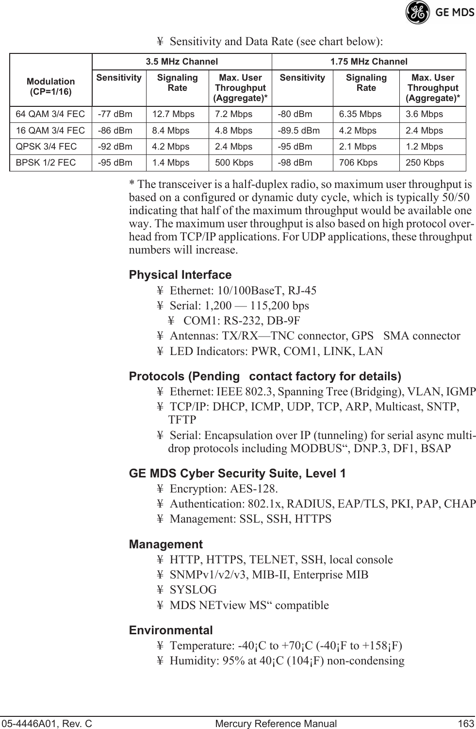
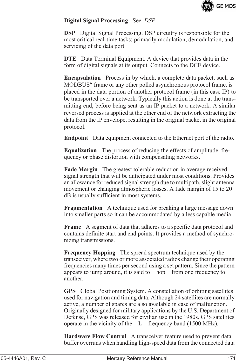
![120 Mercury Reference Manual 05-4446A01, Rev. CInvisible place holderFigure 3-92. Configuration Scripts Menu¥TFTP Host AddressIP address of the computer on which the TFTP server resides. [Any valid IP address]¥Config FilenameName of file containing this units configura-tion profile that will be transferred to the TFTP server. The con-figuration information is in plain-text ASCII format.[Any 40-character alphanumeric string] May require a sub-direc-tory, for example: config\mercury-config.txt. (See Configuration Scripts Menu on Page 119 for more information.)NOTE: The filename field is used to identify the desired incoming fileand as the name of the file exported to the TFTP server. Beforeexporting a units configuration, name it in a way that reflectsthe radios services or other identification.¥Transfer OptionsA menu for configuring the TFTP transfer.¥CategoryThe category of parameters to send or receive.¥Retrieve FileInitiate the file transfer of the configuration file from TFTP server into the transceiver.¥Send FileInitiate the file transfer from the transceivers current configuration file to TFTP server.NOTE: See Upgrade Procedure on Page 117 for details on settingup the TFTP server.Sample of Configuration Script FileA sample configuration script file is provided as part of every firmware release. Firmware images and sample files are available free-of-charge at: www.GEmds.com/Resources/TechnicalSupport/.The name of the specific file includes the firmware revision number, represented by the x characters in the following example: mercury-config-x_x_x.txt.](https://usermanual.wiki/GE-MDS/DS-MERCURY3650.Revised-user-manual-3-of-3/User-Guide-1008948-Page-1.png)
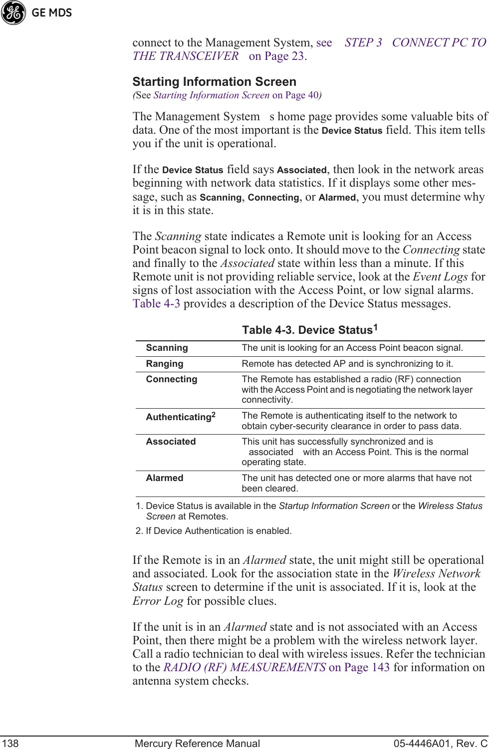
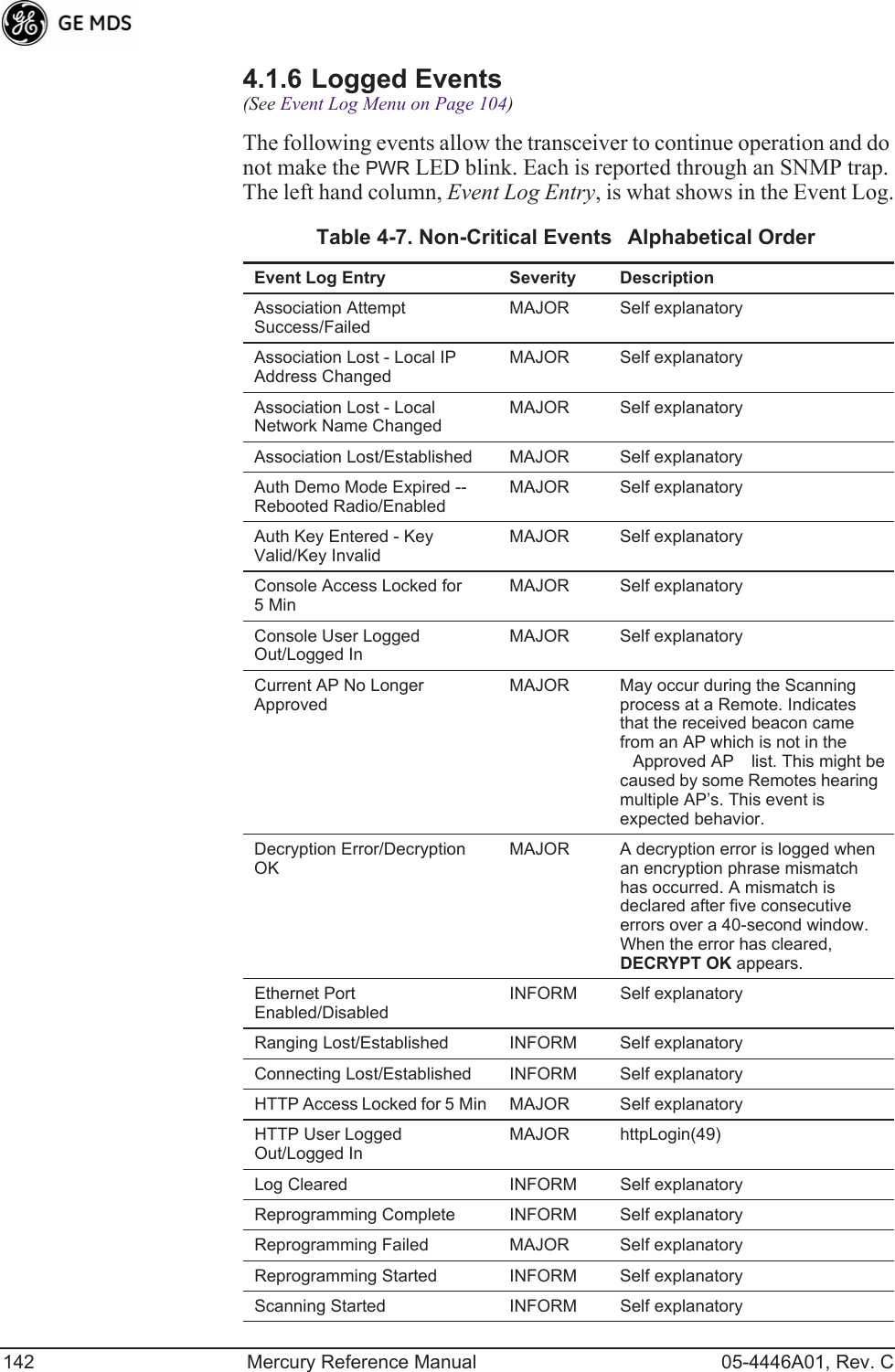
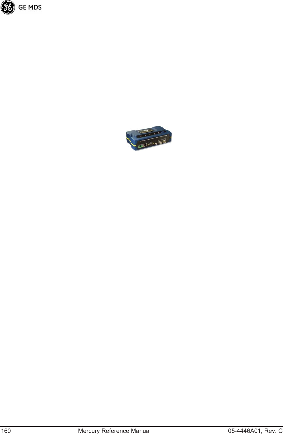
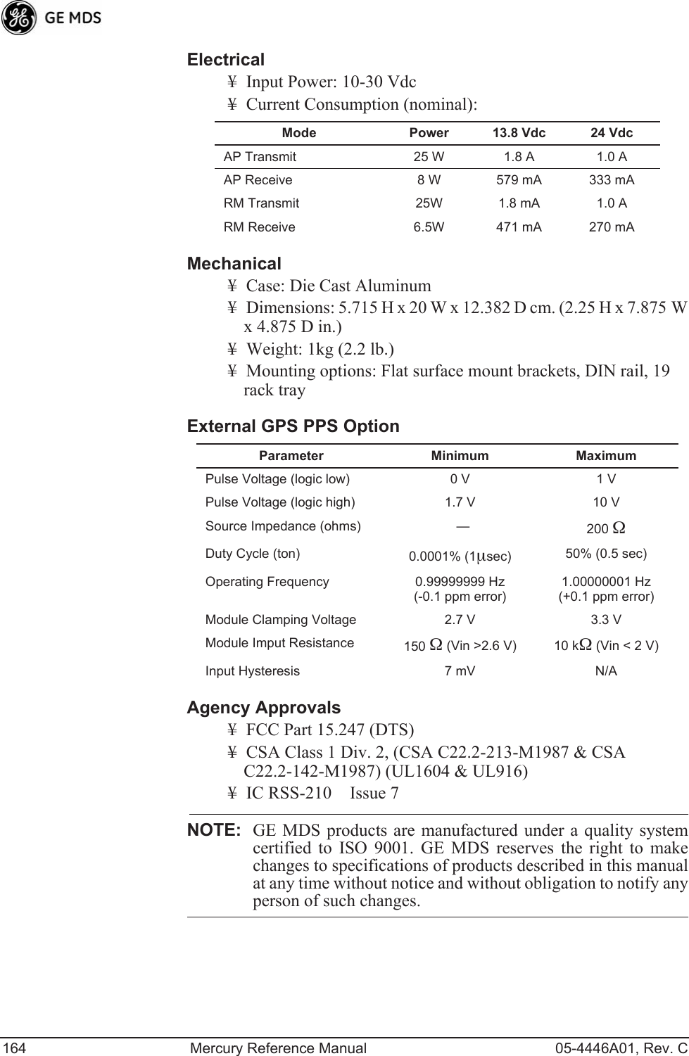
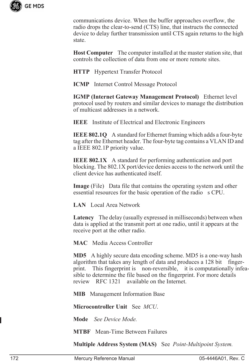
![122 Mercury Reference Manual 05-4446A01, Rev. CPing Utility Menu Invisible place holderFigure 3-93. Ping Utility Menu¥Address to PingAddress to send a Ping. [ Any valid IP address]¥CountNumber of Ping packets to be sent.¥Packet SizeSize of each Ping data packet (bytes).¥PingSend Ping packets to address shown on screen.This screen is replaced with a detailed report of Ping activity (see example in Figure 3-94). Press any key after viewing the results to return to this menu.Invisible place holderFigure 3-94. Ping Results Screen](https://usermanual.wiki/GE-MDS/DS-MERCURY3650.Revised-user-manual-3-of-3/User-Guide-1008948-Page-3.png)
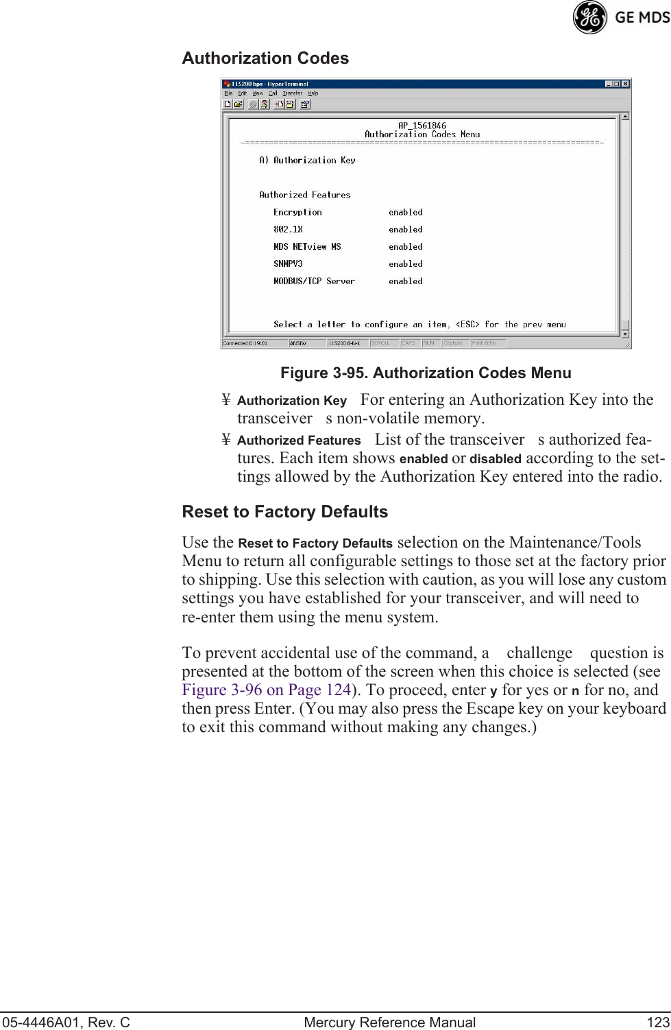
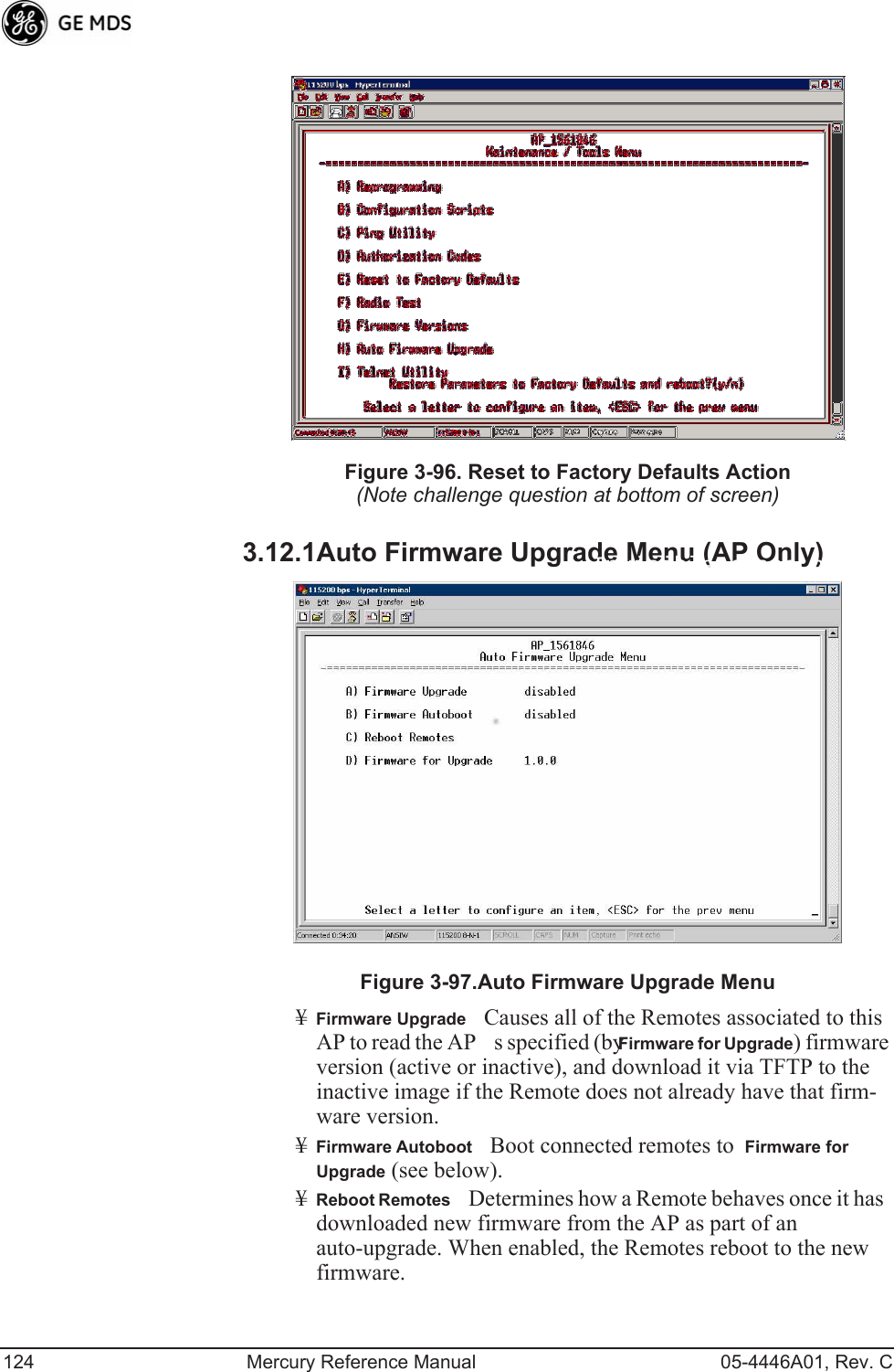
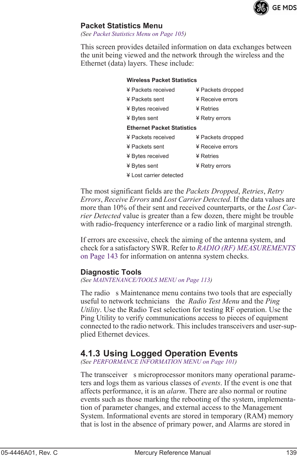
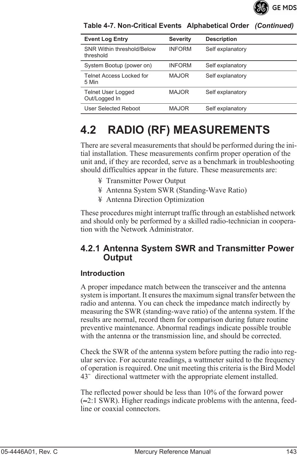
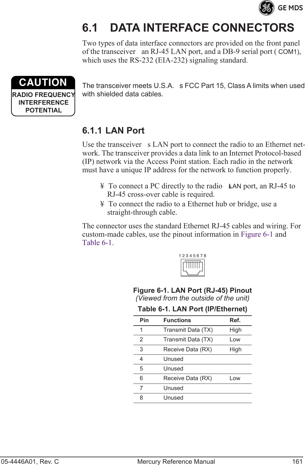
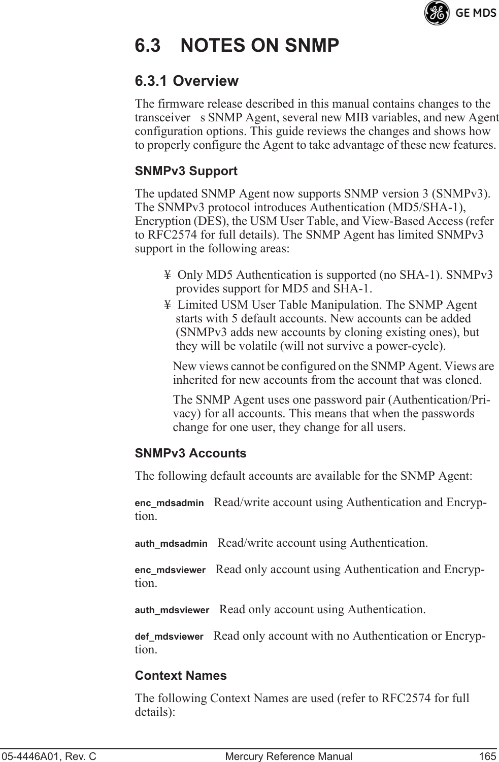
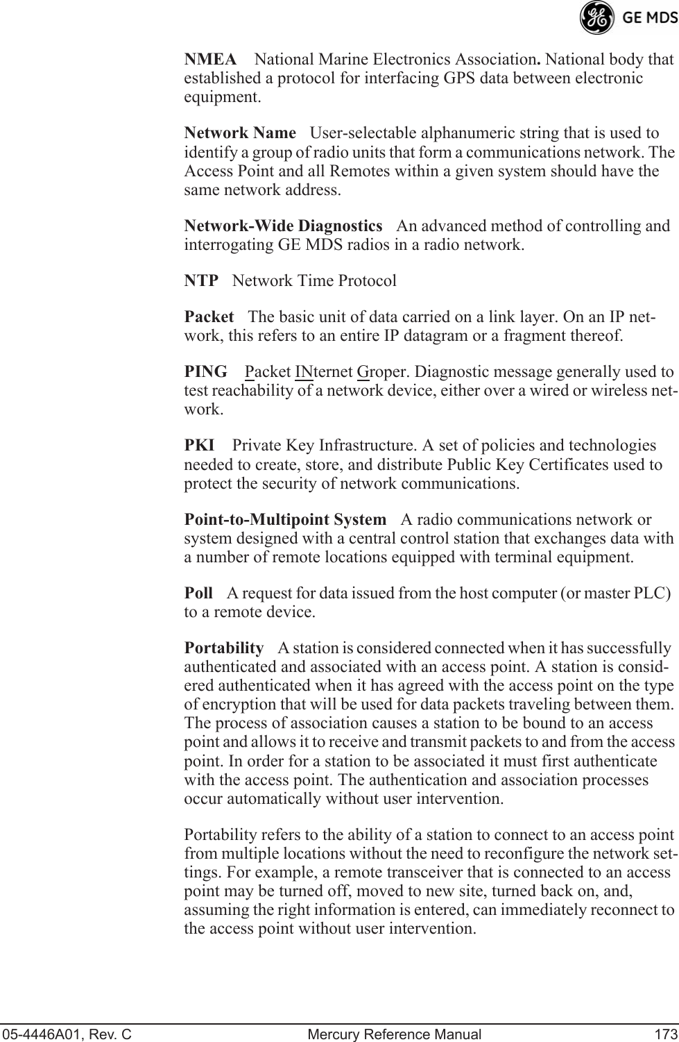
![05-4446A01, Rev. C Mercury Reference Manual 125NOTE: To use the Auto Upgrade/Reboot feature, both the AP andRemotes must already be running version 2.1.0 or newer firm-ware.¥Firmware for UpgradeSpecifies the firmware version that the Remotes should download, if they do not already have it.Radio Test MenuUsing this menu, you can manually key the radio transmitter for perfor-mance checks and set several parameters that will be used when the Radio Mode is set to Test.Invisible place holderFigure 3-98. Radio Test MenuNOTE :Using Test Mode disrupts traffic through the radio. If the unitis an Access Point, it will disrupt traffic through the entirenetwork. The Test Mode function is automatically limited to10 minutes. Only use Test Mode for brief measurements.¥Radio ModeSets/displays the radios operating mode. To change the setting, press A on the PCs keyboard and press the Spacebar to toggle between the two settings. Press the Enter key to select the desired state. [Normal, Test; Normal]¥Test StatusThis read-only parameter shows the current state of the radio. [Radio is Operational, Reconfiguring the Radio, Ready to KEY]The following parameters are read-only unless A) Radio Mode is first selected and set to Test. In Test Mode, these items become selectable, and you can set their entries using the Spacebar or with a numeric entry, followed by pressing the Enter key.¥Test KeySets/displays keying status of the radios transmitter. Use the Spacebar to view selections. [disabled, enabled; disabled]](https://usermanual.wiki/GE-MDS/DS-MERCURY3650.Revised-user-manual-3-of-3/User-Guide-1008948-Page-6.png)
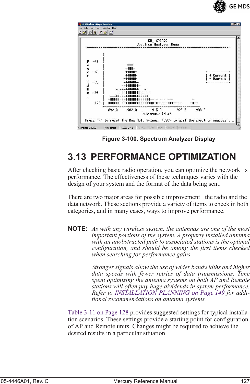
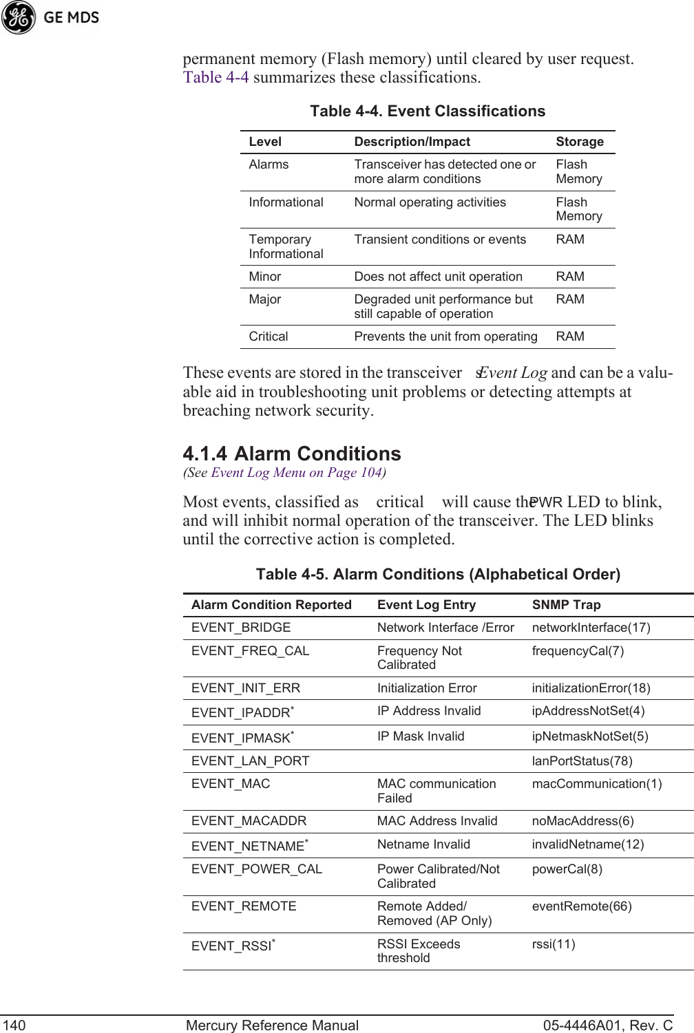
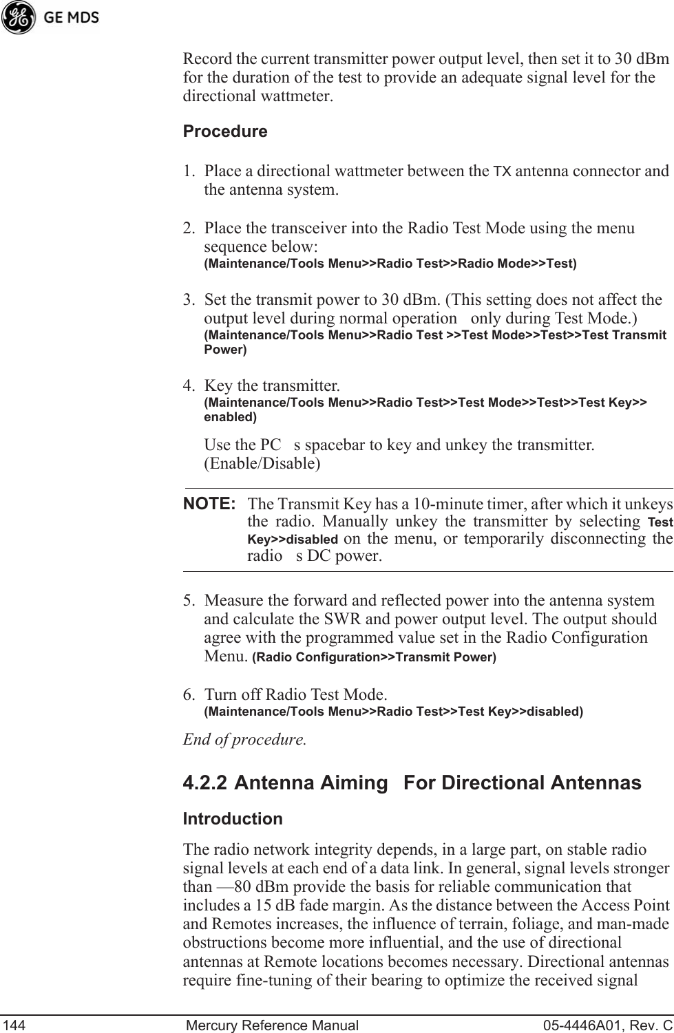
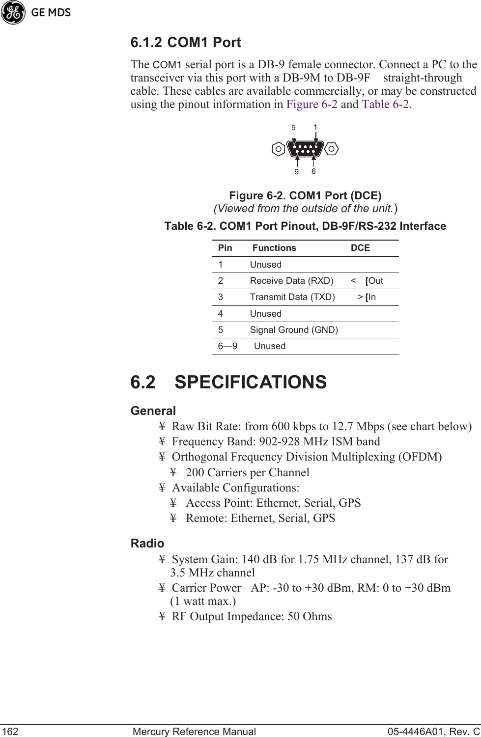
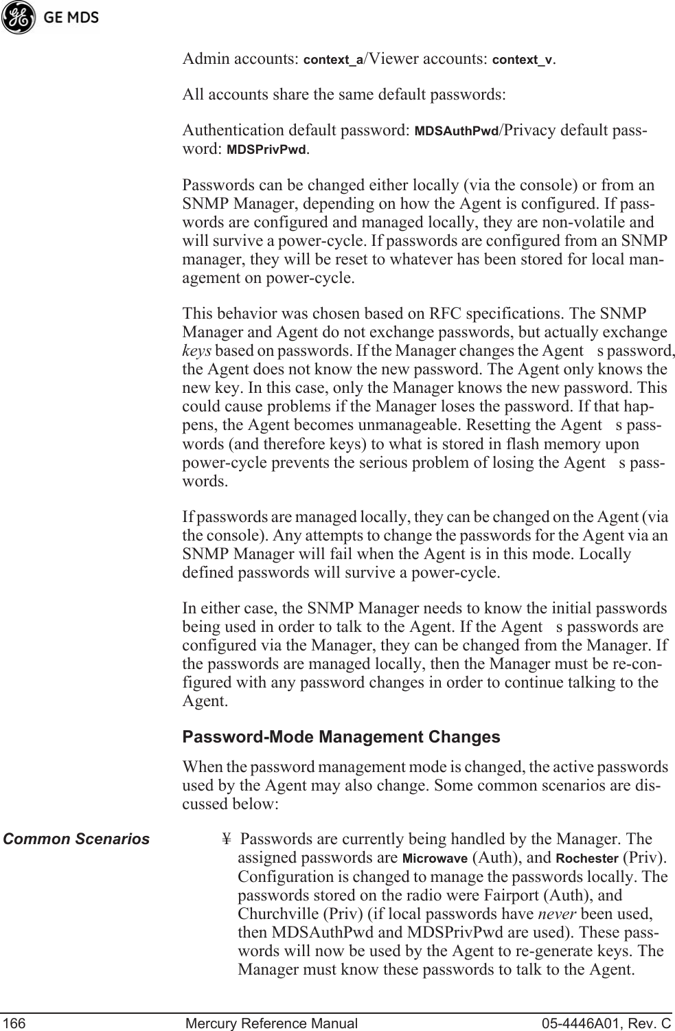
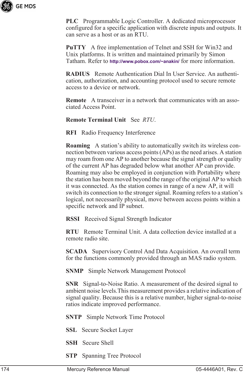
![126 Mercury Reference Manual 05-4446A01, Rev. C¥Test Transmit PowerSets/displays the transmitters power set-ting. Make a numerical entry within the allowable range. [-30 to +30 dBm]¥Test ChannelSets/displays the radios test channel number. Make a numerical entry within the allowable range.[0-13; 0]¥Test RF BandwidthSets/displays the transmitters bandwidth for testing. Use the Spacebar to view selections.[1.75. 3.5 MHz; 1.75 MHz]¥Test Burst PercentageSets/displays the percentage of Burst size to use for testing. Make a numerical entry within the allowable range. [0-100%; 100]Spectrum Analyzer Menu (Remote Only)Using this menu, you can enable or disable the remotes spectrum ana-lyzer mode (Figure 3-99 on Page 126). When enabled, the remote dis-plays through the terminal a spectrum analyzer view of its transmit power and frequency (Figure 3-100 on Page 127).Figure 3-99. Spectrum Analyzer Menu](https://usermanual.wiki/GE-MDS/DS-MERCURY3650.Revised-user-manual-3-of-3/User-Guide-1008948-Page-7.png)