GE MDS DS-MERCURY3650 Wireless IP/Ethernet Transceiver User Manual Book1
GE MDS LLC Wireless IP/Ethernet Transceiver Book1
GE MDS >
Contents
- 1. User manual
- 2. Revised user manual 1 of 3
- 3. Revised user manual 2 of 3
- 4. Revised user manual 3 of 3
Revised user manual 2 of 3
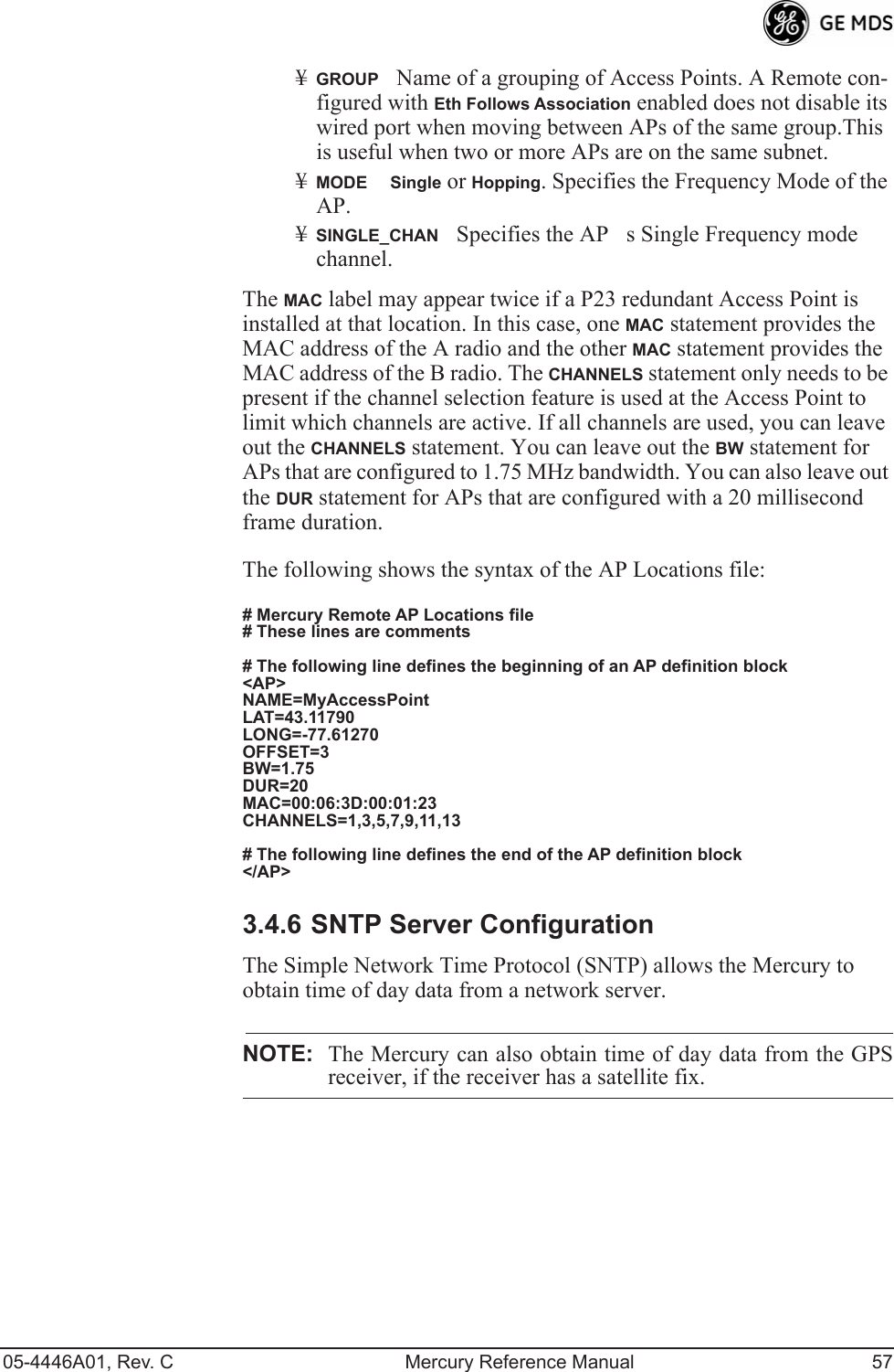
![05-4446A01, Rev. C Mercury Reference Manual 55¥Trap VersionThis specifies which version of SNMP is used to encode the outgoing traps. The choices are v1_traps, v2_traps, and v3_traps. When v3_traps is selected, v2-style traps are sent, but with a v3 header. [v1_traps, v2_traps, v3_traps]¥Auth Traps StatusIndicates whether or not traps are generated for failed authentication of an SNMP PDU. [Disabled/Enabled; Disabled]¥SNMP V3 PasswordsDetermines whether v3 passwords are managed locally or via an SNMP Manager. The different behav-iors of the Agent, depending on the mode selected, are described in SNMP Mode above.¥Trap Manager #1—#4 Table of up to four locations on the net-work to which traps are sent. [Any standard IP address]NOTE: The number in the upper right-hand corner of the screen is theSNMP Agents SNMPv3 Engine ID. Some SNMP Managersmay need to know this ID in order interface with the trans-ceivers SNMP Agent. The ID only appears on the screenwhen SNMP Mode is either v1-v2-v3 or v3_only.NOTE: For more SNMP information, see NOTES ON SNMP onPage 165.3.4.5 AP Location Push Config MenuThis menu configures the AP for updating connected remotes with the AP Locations File loaded on the AP.Invisible place holderFigure 3-23. AP Location Push Config Menu¥TFTP Host AddressIP address of the TFTP server that holds the AP locations file. [any valid IP address; 0.0.0.0]¥Transfer OptionsMenu for configuring the TFTP transfer.](https://usermanual.wiki/GE-MDS/DS-MERCURY3650.Revised-user-manual-2-of-3/User-Guide-1008947-Page-1.png)
![56 Mercury Reference Manual 05-4446A01, Rev. C¥AP Locations FilenameName of the AP Locations file on the server. [any valid filename string; ap_locations.txt]¥Auto AP Location DownloadA setting to force connected remotes to download immediately the AP Locations file on the AP. Remotes that associate to an AP with this feature will also download the file.¥Retrieve Text FileDownload AP Locations text file from the server.¥Send Text FileUpload the local AP Locations file to the server.¥View AP Location FileAllows on-screen review of the AP Loca-tions file. An example screen is shown in Figure 3-24.Invisible place holderFigure 3-24. AP Location Text FileAP Locations File Syntax and GuidelinesThe AP Locations file is used by the Remote radio to determine which Access Point to connect to when operating in Hopping w/ Hand-offs mode. The AP Locations file is a simple text file containing information about the location and configuration of all Access Points that the Remote can associate with. The file is filled in by creating AP definition blocks using tags and labels. The <AP> tag is used to begin a definition block and the </AP> tag ends the block. Within the block, you can declare sev-eral parameters using a LABEL=VALUE syntax. The possible labels are: ¥NAMEThe name of the AP. Typically set to the Device Name configured on the AP¥LATGPS Latitude of the AP in decimal degrees¥LONGGPS Longitude of the AP in decimal degrees¥OFFSETPattern Offset configured on the AP¥BWBandwidth (1.75 or 3.5) configured on the AP¥DURFrame duration (10 or 20) configured on the AP¥MACThe Wireless MAN Address configured on the AP¥CHANNELSSpecifies which channels are being used by the AP](https://usermanual.wiki/GE-MDS/DS-MERCURY3650.Revised-user-manual-2-of-3/User-Guide-1008947-Page-2.png)
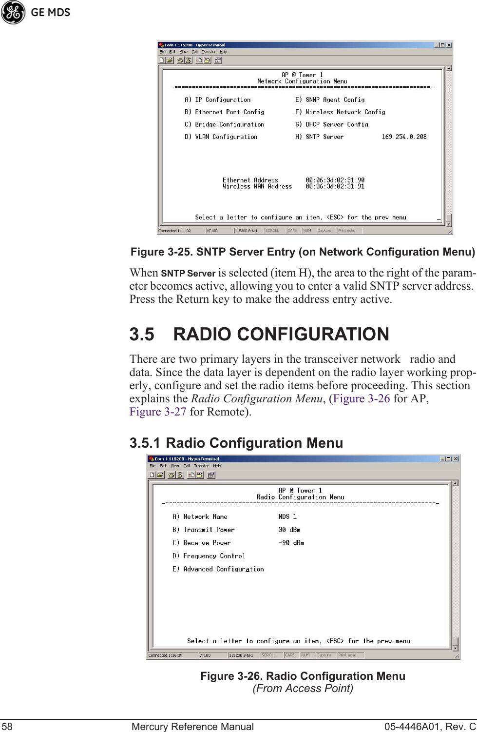
![05-4446A01, Rev. C Mercury Reference Manual 59Figure 3-27. Radio Configuration Menu(From Remote Unit)¥Network NameThe user-defined name for the wireless network. [Any 40 character string; MDS-Mercury]¥Transmit Power (AP Only)Sets/displays RF power output level in dBm. This setting should reflect local regulatory limitations and losses in antenna transmission line. (See How Much Out-put Power Can be Used? on Page 155 for information on how to calculate this value.) [0—30; 30]¥Max Transmit Power (Remote Only)Sets/displays maximum RF power output level in dBm of the Remote. Power level is still controlled by the AP, but it is limited to the maximum level set here. This setting should reflect local regulatory limitations and losses in antenna transmission line. (See How Much Output Power Can be Used? on Page 155 for information on how to calculate this value.) [0—30; 30]¥Receive Power (AP Only)View/set the receiver gain setpoint for the expected strength of incoming signals from Remotes. This setting indicates at what level (in dBm) the AP expects to hear the Remote stations. A setting of -70 would set the AP receivers gain to a relatively low level, while a setting of -85 would be a comparatively high gain setting. [-100 to -20; -75]¥Frequency ControlOpens a submenu where you can view or set frequency mode bandwidth, channel and other parameters as described in Frequency Control Menu below.¥Advanced ConfigurationOpens a submenu where you can view or set modulation, protection/hysteresis margins, data compres-sion, ARQ settings, and other parameters as described in Advanced Configuration Menu on Page 65.](https://usermanual.wiki/GE-MDS/DS-MERCURY3650.Revised-user-manual-2-of-3/User-Guide-1008947-Page-5.png)
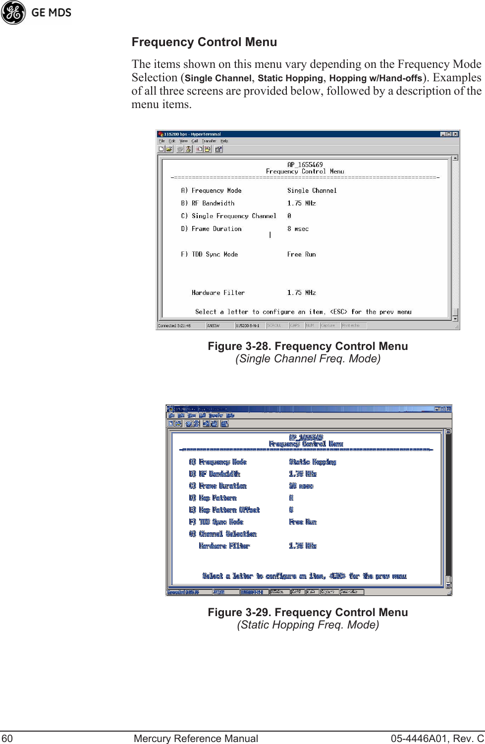
![05-4446A01, Rev. C Mercury Reference Manual 61Invisible place holderFigure 3-30. Frequency Control Menu(Hopping w/Hand-offs Freq. Mode [Remote only])¥Frequency ModeThe unit can operate on one selected fre-quency or frequency hop. Remotes have the option of using a static hopping configuration or using the AP locations file to select an AP and perform hand-offs. For more information on hand-offs, see Table 3-2 on Page 64. Changing this parameter requires a radio reboot.[Static Hopping, Hopping with Hand-offs, Single Channel; Single Channel]NOTE: Frequency Mode Static Hopping on Access Points requiresTDD Sync Mode GPS Required.Channel/Frequency Allocations for Single Channel operation are shown in Table 3-1. The transceiver utilizes up to 14 chan-nels (0-13) depending on the bandwidth used (1.75 MHz or 3.5 MHz).Table 3-1. Channel/Frequency AllocationsChannel 1.75 MHz B/W 3.5 MHz B/W0 903.000000 904.0000001 904.800000 907.6000002 906.600000 911.4000003 908.600000 915.0000004 910.400000 918.6000005 912.200000 922.4000006 914.000000 926.0000007 916.0000008 917.8000009 919.600000](https://usermanual.wiki/GE-MDS/DS-MERCURY3650.Revised-user-manual-2-of-3/User-Guide-1008947-Page-7.png)
![62 Mercury Reference Manual 05-4446A01, Rev. C¥RF BandwidthView/set the radios RF operating bandwidth. Radios are factory-configured for either 1.75 MHz or 3.5 MHz maximum bandwidth. Determine the factory configuration of a radio by viewing the CONFIG number on the label at the bot-tom of the radio. 1.75 MHz units will have a Configuration string starting with HGA/R9N1, and 3.5 MHz units will have a string starting with HGA/R9N3.The bandwidth setting on this menu does not necessarily have to match the configured bandwidth of the radio, but it is limited by it. That is, you can set a 3.5 MHz radio to either 1.75 or 3.5, but you can only set a 1.75 MHz radio to 1.75. Note that setting a 3.5 MHz bandwidth radio to operate at 1.75 MHz bandwidth will cause a slight degradation of interference rejection capabil-ity. [1.75MHz, 3.5MHz]¥Hop PatternSelects a pre-defined series of channels that is fol-lowed when hopping.¥Hop Pattern OffsetInserts an offset into the hop pattern that is synchronized with the GPS. For example, if the offset is 0, then the start of the pattern is aligned with the GPS timing. If the off-set is 3, then the fourth hop of the pattern is aligned with the GPS timing. All of the APs that are part of a network should use the same pattern and each one should have its own offset. In the diagram below, one Remote is configured for static hop-ping and will only associate with AP1 because they are both 10 921.40000011 923.40000012 925.20000013 927.000000Table 3-1. Channel/Frequency AllocationsChannel 1.75 MHz B/W 3.5 MHz B/W](https://usermanual.wiki/GE-MDS/DS-MERCURY3650.Revised-user-manual-2-of-3/User-Guide-1008947-Page-8.png)
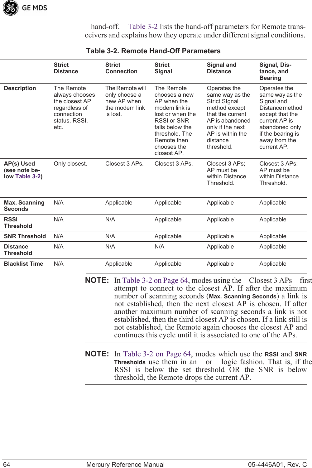
![05-4446A01, Rev. C Mercury Reference Manual 63using Offset 0. The hand-off configured Remote, using its AP Locations file, may connect to AP1, AP2, or AP3. The Remote does this by determining the Offset for each AP, then configur-ing its radio.¥Current APShows the name of the AP that the Remote is trying to associate with.¥Advanced ControlProvides access to frequency setup parame-ters.¥TDD Sync ModeIndicates if the Access Points transmissions should synchronize with the GPS timing. Configure this param-eter to GPS Required when the AP is configured for Static Hopping. TDD Sync Mode (Time-Division Duplex) is useful in eliminat-ing same-network interference for multiple-AP installations. When enabled, all AP transmissions are synchronized using GPS timing information. The result is that no AP transmits while another is receiving, which prevents AP-to-AP interfer-ence. Changing this parameter requires a radio reboot.[Free Run, GPS Required; Free Run] Note: Do not use the Prefer GPS setting.¥Channel SelectionOpens a submenu where you can specify channel usage.¥Single Frequency ChannelThe RF frequency that the integrated radio will operate on when in single frequency (non-hopping) mode. [0 to 6 for 3.5-MHz, 0 to 13 for 1.75-MHz; 0].¥Frame DurationDefines the over-the-air media access control framing. [5, 8, 10, or 20 msec; 20 msec]¥Hardware FilterThis field provides a read-only indication of the maximum bandwidth of the radio. [1.75 MHz or 3.5 MHz]Hand-Off Mode Parameters Remote radios can move and associate with different APs depending on their locations. The process by which the Remote ends the connection with one AP and begins a connection with another AP is called AP 1 Pattern A Offset 0 AP 2 Pattern A Offset 1 AP 3 Pattern A Offset 2 RM Static Hopping Offset 0 RM Hopping w/ Hand-offs](https://usermanual.wiki/GE-MDS/DS-MERCURY3650.Revised-user-manual-2-of-3/User-Guide-1008947-Page-9.png)
![05-4446A01, Rev. C Mercury Reference Manual 65Advanced Configuration Menu Invisible place holderFigure 3-31. Advanced Configuration Menu¥Adaptive ModulationEnables automatic selection of modulation and FEC rate based on SNR. [enabled, disabled; enabled]¥Protection MarginA number of decibels of SNR added to the minimum SNR required for a given modulation and FEC rate. See Modulation Protection and Hysteresis Margins on Page 66 for more information. [0-50; 3]¥Hysteresis MarginA number of decibels of SNR added to the maximum SNR required before shifting to the next higher mod-ulation and FEC rate. See Modulation Protection and Hyster-esis Margins on Page 66 for more information. [0-50; 3]¥Data CompressionThis setting determines whether over-the-air data packets will be compressed. [enabled, disabled; enabled]¥Max ModulationSets the highest modulation speed the trans-ceiver will use.[BPSK, QPSK-1/2, QPSK-3/4, 16QAM-1/2, 16QAM-3/4, 64QAM-2/3, 64QAM-3/4; QAM16-3/4]¥Cyclic PrefixAmount of additional information added to the over-the-air packets to mitigate the effects of channel multipath. [1/4, 1/8, 1/16,1/32; 1/16]¥Channel TypeThis parameter, available on Access Point units, must be set appropriately according to the signal conditions of a network. For installations with strong signals, low interference, and minimal fading, set the Channel Type parameter to Static. This setting is generally appropriate for Access Points whose Remotes are in fixed locations. It supports a large offered pay-load with high packet rates. For installations with significant interference and fading or nomadic Remotes, set the Channel Type parameter to Dynamic. [Static, Dynamic; Static]](https://usermanual.wiki/GE-MDS/DS-MERCURY3650.Revised-user-manual-2-of-3/User-Guide-1008947-Page-11.png)
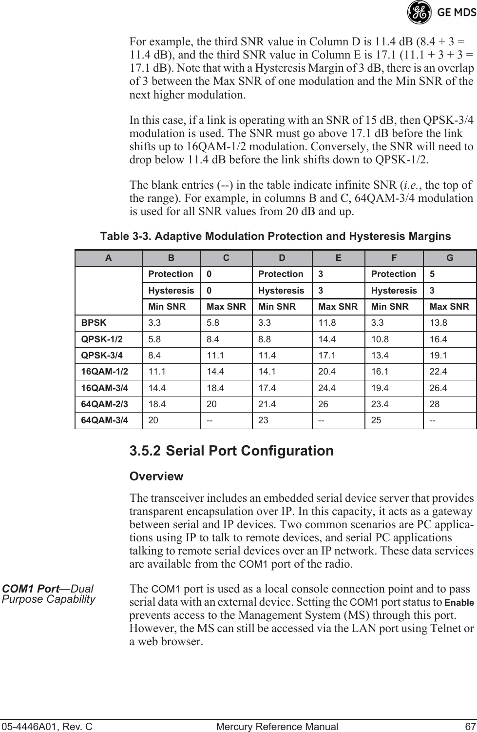
![66 Mercury Reference Manual 05-4446A01, Rev. C¥ARQEnables the Automatic Repeat Request function. [enable, disable; enabled]¥ARQ Window SizeThe maximum number of blocks to send before receiving an acknowledgement. [1—1024; 512]¥ARQ Block SizeARQ is applied to payload data in blocks of this size. [4—2040; 256]¥ARQ Block LifetimeARQ blocks are valid for this length of time. [0—655; 655]¥ARQ Transmitter DelayThe length of time the transmitter waits before repeating an unacknowledged packet.[1—655; 35]¥ARQ Receiver DelayThe length of time the receiver waits before repeating an unacknowledged packet. [1—655; 35]¥Downlink PercentageThe percentage of link time given to downstream traffic. It should be set to 50% when Adaptive Split is set to enabled. [10-90%; 50%]¥Adaptive SplitThe adaptive split feature provides improved link utilitization and throughput for burst payload traffic. The Mercury is a TDD system and normally allocates 50% of its capacity to the downlink and 50% to the uplink. When adaptive split is enabled, the Media Access Controller (MAC) in the Access Point monitors the traffic flow continuously in the downlink and uplink directions. The MAC auotmatically modi-fies the downlink split in response to the traffic load. When more traffic is flowing upstream, the downlink split changes to allocate additional capacity to the uplink. When more traffic is flowing downstream, the downlink gets additional capacity. If TDD synchronization is used to synchronize Access Points and minimize inter-Access Point interference, Adaptive Split should be disabled. [enabled, disabled; enabled]Modulation Protection and Hysteresis MarginsTable 3-3 on Page 67 shows the relationship between the radios Protec-tion Margin, Hysteresis Margin, and the SNR range allowed for each form of modulation.Column A lists the available modulation types for the radio, while col-umns B and C show the minimum SNR range required to operate in each modulation. For example, an SNR of 5.8 dB in Column B is required for QPSK modulation with an FEC rate of 1/2. An SNR of 8.4 dB is required for QPSK modulation with an FEC rate of 3/4.Columns B and C have a Hysteresis Margin of 0 dB. This means there is no overlap between the maximum SNR for BPSK (5.8 dB) and the minimum SNR for QPSK-1/2 (5.8 dB).Columns D and E show the SNR ranges with a Protection Margin and Hysteresis Margin of 3 dB. The Protection Margin is added to each value in Columns B and C to get the corresponding value in Columns D and E. The Hysteresis Margin is then added to the Max SNR value.](https://usermanual.wiki/GE-MDS/DS-MERCURY3650.Revised-user-manual-2-of-3/User-Guide-1008947-Page-12.png)
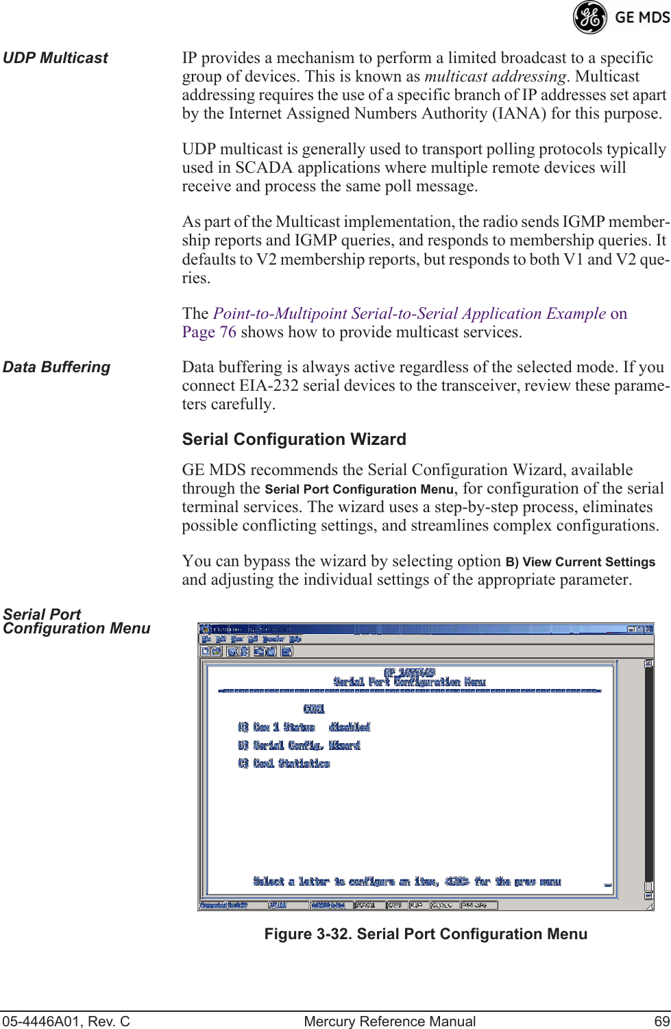
![70 Mercury Reference Manual 05-4446A01, Rev. C Figure 3-33. Serial Configuration Wizard¥Begin WizardTool for configuring serial ports using a step-by-step process.¥View Current SettingsDisplays all setable options. Varies depending on the selected IP protocol.Configuring for UDP Point-to-Multipoint Invisible place holderFigure 3-34. UDP Point-to-Multipoint MenuUse UDP point-to-multipoint to send a copy of the same packet to mul-tiple destinations, such as in a polling protocol.¥StatusEnable/Disable the serial data port.¥ModeThe type of IP port offered by the transceivers serial device server. [TCP, UDP; TCP]](https://usermanual.wiki/GE-MDS/DS-MERCURY3650.Revised-user-manual-2-of-3/User-Guide-1008947-Page-16.png)
![05-4446A01, Rev. C Mercury Reference Manual 71¥RX IP PortReceive IP data from this source and pass it through to the connected serial device. The port number must be used by the application connecting to local TCP or UDP socket. [Any valid IP port; 30010]¥TX IP Address (used instead of Local IP Address when using UDP Point-to-Multipoint) Configure with a valid Multi-cast address (224.0.0.0—239.255.255.255). IP packets received with a matching destination address are processed by this unit. [Any legal IP address; 0.0.0.0]¥TX IP Port (used instead of Local IP Port when using UDP Point-to-Multipoint)This port number must match the number used by the application connecting to local TCP or UDP socket. [1-64,000; 30010]¥Baud RateData rate (payload) for the COM port, in bits-per-second. [1,200—115,200; 19200] ¥Byte FormatFormatting of data bytes, representing data bits, parity and stop bits. [7N1, 7E1, 7O1, 8N1, 8E1, 8O1, 8N1, 7N2, 7E2, 7O2, 8N2, 8E2, 8O2; 8N1]¥Buffer SizeMaximum amount of characters that the Remote end buffers locally before transmitting data through the serial port. [1—255; 255]¥Inter-Packet DelayAmount of time that signal the end of a message, measured in tenths of a second. [default = 1 (that is, 1/10th of a second)]¥Commit Changes and Exit WizardSave and execute changes made on this screen (shown only after changes have been entered). Invisible place holderFigure 3-35. UDP Point-to-Point MenuConfiguring for UDP Point-to-Point Use UDP point-to-point configuration to send information to a single device.¥StatusEnable/Disable the serial data port.](https://usermanual.wiki/GE-MDS/DS-MERCURY3650.Revised-user-manual-2-of-3/User-Guide-1008947-Page-17.png)
![72 Mercury Reference Manual 05-4446A01, Rev. C¥ModeUDP Point-to-Point. This is the type of IP port offered by the transceivers serial device server. [TCP, UDP; TCP]¥RX IP PortPort number where data is received and passed through to the serial port. The application connecting to this transceiver must use this port number.[1—64,000; 30010]¥TX IP AddressData received through the serial port is sent to this IP address. To reach multiple Remotes in the network, use UDP Point-to-Multipoint. [Any legal IP address; 0.0.0.0]¥TX IP PortThe destination IP port for data packets received through the serial port on the transceiver. [1—64,000; 30010]¥Talkback EnableTalkback is a mode where the radio returns a serial message received within a time-out period back to the last address of an incoming UDP message. If the time-out expires, the unit sends the serial data to the configured address. [Enable, Disable; Disabled]¥Baud RateData rate (payload) for the COM port, in bits-per-second. [1,200—115,200; 19200] ¥Byte FormatFormatting of data bytes. Data bits, parity and stop bits. [7N1, 7E1, 7O1, 8N1, 8E1, 8O1, 8N1, 7N2, 7E2, 7O2, 8N2, 8E2, 8O2; 8N1]¥Buffer SizeMaximum amount of characters that the Remote end buffers locally before transmitting data through the serial port. [1—255; 255]¥Inter-Packet DelayAmount of time that signal the end of a message, measured in tenths of a second. [default = 1 (that is, 1/10th of a second)]¥Commit Changes and Exit WizardSave and execute changes made on this screen (shown only after changes have been entered).](https://usermanual.wiki/GE-MDS/DS-MERCURY3650.Revised-user-manual-2-of-3/User-Guide-1008947-Page-18.png)
![05-4446A01, Rev. C Mercury Reference Manual 73Configuring for TCP Mode Invisible place holderFigure 3-36. TCP Client Menu (Remote)¥StatusEnable/Disable the serial data port. ¥ModeTCP Client. This is the type of IP port offered by the transceivers serial device server. [TCP, UDP; TCP]¥TX IP AddressThe IP address to be used as a destination for data received through the serial port.[Any legal IP address; 0.0.0.0]¥TX IP PortThe destination IP port for data packets received through the serial port on the transceiver.[Any valid IP port; 30010]¥TCP KeepaliveAmount of time (in seconds) that the trans-ceiver waits for data before terminating the TCP session. [0—600; 600]¥Baud RateData rate (payload) for the COM port, in bits-per-second. [1,200—115,200; 19200] ¥Byte FormatInterface signaling parameters. Data bits, parity and stop bits. [7N1, 7E1, 7O1, 8N1, 8E1, 8O1, 8N1, 7N2, 7E2, 7O2, 8N2, 8E2, 8O2; 8N1]¥Buffer SizeMaximum amount of characters that the Remote end buffers locally before transmitting data through the serial port. [1—255; 255]¥Inter-Frame Packet DelayA measurement representing the end of a message, measured in tenths of a second.[default = 1 (that is, 1/10th of a second)]¥Commit Changes and Exit WizardSave and execute changes made on this screen (shown only after changes have been entered).](https://usermanual.wiki/GE-MDS/DS-MERCURY3650.Revised-user-manual-2-of-3/User-Guide-1008947-Page-19.png)
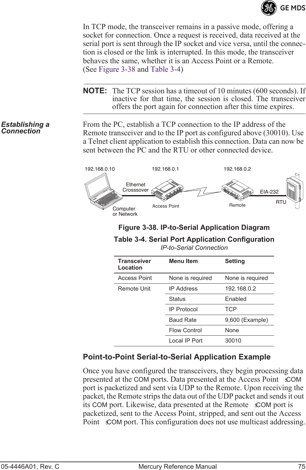
![74 Mercury Reference Manual 05-4446A01, Rev. CInvisible place holderFigure 3-37. TCP Server Menu (AP)¥StatusEnable/Disable the serial data port.¥ModeTCP Server. This is the type of IP port offered by the transceivers serial device server. [TCP, UDP; TCP]¥RX IP PortReceive IP data from this source and pass it through to the connected serial device. The application con-necting to the local TCP or UDP socket must use this port number.[Any valid IP port; 30010]¥Baud RateData rate (payload) for the COM port, in bits-per-second. [1,200—115,200; 19200] ¥Byte FormatInterface signaling parameters. Data bits, parity and stop bits. [7N1, 7E1, 7O1, 8N1, 8E1, 8O1, 8N1, 7N2, 7E2, 7O2, 8N2, 8E2, 8O2; 8N1]¥Buffer SizeMaximum amount of characters that the Remote end buffers locally before transmitting data through the serial port. [1—255; 255]¥Inter-Packet DelayAmount of time that signal the end of a message, measured in tenths of a second. [default = 1 (that is, 1/10th of a second)]¥Commit Changes and Exit WizardSave and execute changes made on this screen (shown only after changes have been entered).IP-to-Serial Application ExampleYou must choose UDP or TCP to establish communications. This depends on the type of device you are communicating with at the other end of the IP network. In this example, we will use TCP to illustrate its use.](https://usermanual.wiki/GE-MDS/DS-MERCURY3650.Revised-user-manual-2-of-3/User-Guide-1008947-Page-20.png)
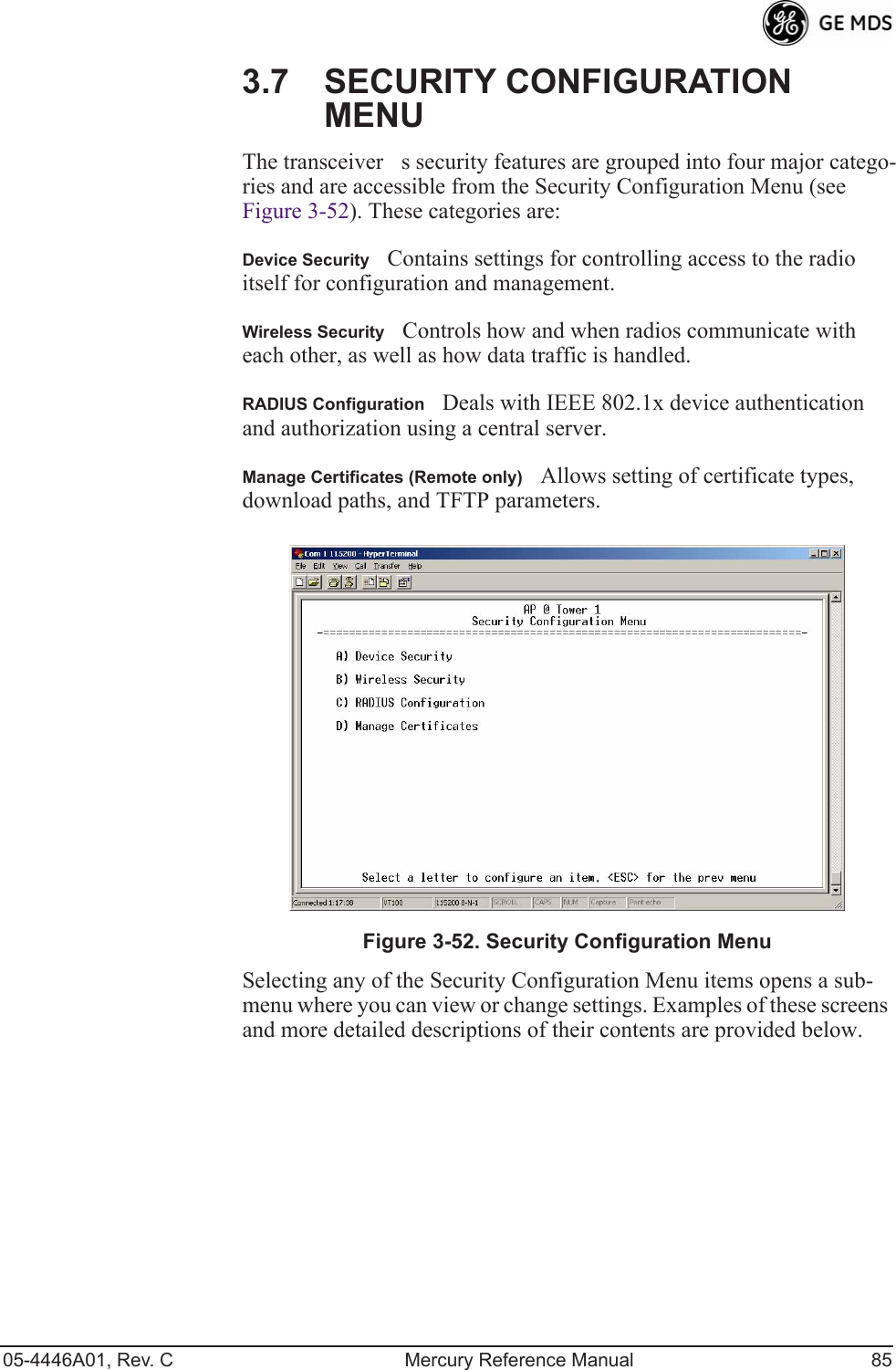
![86 Mercury Reference Manual 05-4446A01, Rev. C3.7.1 Device Security MenuThe Device Security Menu (Figure 3-53) controls how the radios can be accessed either locally or remotely for configuration and management.Invisible place holderFigure 3-53. Device Security Menu¥Telnet AccessControls Telnet access to the transceivers man-agement system. [enabled, disabled; enabled]¥SSH AccessControls access to the Secure Shell (SSH) server.[enabled, disabled; enabled]¥HTTP ModeControls access to the transceivers management system via the web server. [disabled, HTTP, HTTPS; HTTP]¥HTTP Auth ModeSelects the mode used for authenticating a web user. [Basic Auth, MD5 Digest; Basic Auth]¥User Auth MethodView/set the method of authentication for users. [Local, Radius; Local]¥User Auth FallbackView/set method of authentication to use if the RADIUS server is unavailable. [None, Local; None] ¥User PasswordsAllows changing of Administrative and Guest passwords. When selected, a new screen appears (Figure 3-54 on Page 87).](https://usermanual.wiki/GE-MDS/DS-MERCURY3650.Revised-user-manual-2-of-3/User-Guide-1008947-Page-32.png)
![05-4446A01, Rev. C Mercury Reference Manual 87User Passwords Menu Invisible place holderFigure 3-54. User Passwords MenuTo change the Administrator or Guest password, select the appropriate menu item (A or B). A flashing cursor appears to the right. From here, type the new password, which can be any alpha-numeric string up to 13 characters long. The change is asserted when you press the Return key.¥Change Admin PasswordAllows you to set a new password. [any alpha-numeric string up to 13 characters; admin]¥Change Guest PasswordAllows you to set a new password. [any alpha-numeric string up to 13 characters; guest]TIP: For enhanced security, consider using misspelled words, a combi-nation of letters and numbers, and a combination of upper and lower case letters. Also, the more characters used (up to 13), the more secure the password. These strategies help protect against sophisticated hackers who use a database of common words (for example, dictionary attacks) to determine a password.3.7.2 Wireless Security MenuThe features in the Wireless Security menu (Figure 3-55 on Page 88) control the communication of data across the wireless link. You can authenticate the radios locally via a list of authorized radios, or remotely via a centralized IEEE 802.1x device authentication server. This server provides a centralized authentication mechanism based on standards.](https://usermanual.wiki/GE-MDS/DS-MERCURY3650.Revised-user-manual-2-of-3/User-Guide-1008947-Page-33.png)
![88 Mercury Reference Manual 05-4446A01, Rev. CInvisible place holderFigure 3-55. Wireless Security Menu¥Device Auth ModeView/set the devices authentication method. [None, Local, IEEE 802.1X; None]¥Data EncryptionControls the over-the-air payload datas AES-128 bit encryption. [enable, disable; disabled]¥Encryption PhraseView/set the phrase used to generate encryp-tion keys when encrypting over-the-air payload. [any alpha-numeric string of 8 to 15 characters; <empty>]¥Max Remotes (AP only)The maximum number of remotes an AP can associate with.¥Approved Remotes (AP only)Launches a submenu where you can view, add, or delete approved Remotes. (See Figure 3-56.)Approved Remotes Submenu Setting the Device Auth Mode to Local forces an AP to check the Approved Remotes List before establishing a radio link. A Remote must be in the list before the AP associates and grants authorization. Before enabling this option, at least one entry must already exist in the View Approved Remotes list.](https://usermanual.wiki/GE-MDS/DS-MERCURY3650.Revised-user-manual-2-of-3/User-Guide-1008947-Page-34.png)
![05-4446A01, Rev. C Mercury Reference Manual 89Invisible place holderFigure 3-56. Approved Remotes Submenu¥Add RemoteEnter the MAC address of Remote.[Any valid 6-digit hexadecimal MAC address; 00:00:00:00:00:00] ¥Delete RemoteEnter the MAC address of Remote. For security purposes, you should delete a stolen or deprovisioned radio from this list.¥Add Associated RemotesAdd all currently associated remotes to the approved remote list. Alternatively, you can enter each Remote MAC manually.¥Delete All RemotesRemove (complete purge) all Remotes from current list.¥View Approved RemotesListing of approved Remotes by MAC address. These radios are authorized to join this AP. If a Remote is not in this list, it cannot associate with this AP.3.7.3 IEEE 802.1x Device AuthenticationThis section covers the configuration needed for the radios to access the IEEE 802.1x device authentication server, which provides Device Level Security and for Wireless Access Security. GE MDS does not provide the server software.Operation of Device AuthenticationDevice authentication forces the radio to authenticate before allowing user traffic to traverse the wireless network. When Device Security is configured to use IEEE 802.1x as the Authentication Method, Remote radios need three types of certificates: public (client), private, and root (Certificate Authority). These files are unique to each Remote radio and must first be created at the server and then installed into each unit via TFTP. The certificate files must be in DER format.Device authentication uses the serial number of each radio as the Common Name (CN) in its certificate and in its RADIUS identity field.](https://usermanual.wiki/GE-MDS/DS-MERCURY3650.Revised-user-manual-2-of-3/User-Guide-1008947-Page-35.png)
![05-4446A01, Rev. C Mercury Reference Manual 91RADIUS Configuration Menu Invisible place holderFigure 3-57. Radius Configuration Menu¥Auth Server AddressThe IP address of the authentication server. [any valid IP address; 0.0.0.0]¥Auth Server PortThe UDP Port of the authentication server. [1812, 1645, 1812]¥Auth Server Shared SecretUser authentication and Device authentication require a common shared secret to complete an authentication transaction. This entry must match the string used to configure the appropriate files on the authentication server. [<empty>; any alpha-numeric string up to 16 characters]¥User Auth ModeRADIUS Authentication algorithm.[PAP, CHAP, EAP; PAP]NOTE: CHAP is more secure than PAP. PAP may display the loginpassword in log files at the authentication server while CHAPwill encrypt the login password.3.7.4 Manage CertificatesUse Certificate generation software to generate certificate files, then install these files into each Remote unit using TFTP. This is done using the Manage Certificates Menu (Figure 3-58 on Page 92). The certificate files must be in DER format. The Common Name (CN) field in the public certificate file must match the serial number of the unit it is installed on.](https://usermanual.wiki/GE-MDS/DS-MERCURY3650.Revised-user-manual-2-of-3/User-Guide-1008947-Page-37.png)
![92 Mercury Reference Manual 05-4446A01, Rev. CInvisible place holderFigure 3-58. Manage Certificates Menu¥TFTP Host Address(Telnet/Terminal only)IP address of the com-puter on which the TFTP server resides. This same IP address is used in other screens/functions (reprogramming, logging, etc.). Changing it here also changes it for other screens/functions.[Any valid IP address; 127.0.0.1].¥Transfer OptionsA menu for configuring the TFTP transfer. (See Figure 3-59 on Page 93.)Three certificate files (Root CA, Client, and Private Key) must be present in each of the Remote radios. Use the commands described below to install these files into each Remote radio:¥Certificate TypeSelects one of the three certificate file types mentioned above. [Root CA, Client, Private Key; Root CA]¥Certificate FilenameSpecifies the software path and filename for downloading certificates.¥Retrieve CertificateInitiates the retrieval of the certificate file from the storage location. A successful installation issues a Com-plete status message.NOTE: It is imperative that the three certificate files are installedcorrectly into the Remote radio, in their respective file types.If they are not, the Remote is un-authenticated for data traffic.Consult your network administrator for more information.](https://usermanual.wiki/GE-MDS/DS-MERCURY3650.Revised-user-manual-2-of-3/User-Guide-1008947-Page-38.png)
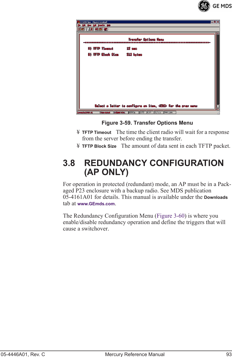
![94 Mercury Reference Manual 05-4446A01, Rev. CInvisible place holderFigure 3-60. Redundancy Configuration Menu (AP Only)¥Redundancy ConfigurationEnable/disable redundancy switcho-ver for AP. [enabled, disabled; disabled]¥Network Event TriggersThis selection opens a submenu (Figure 3-61 on Page 95) where you can set/view the trigger sta-tus for Network Events.¥Radio Event TriggersThis selection opens a submenu (Figure 3-62 on Page 95) where you can set/view the trigger sta-tus for Radio Events, such as a loss of associated Remotes or excessive packet errors.¥Hardware Event TriggersThis selection opens a submenu (Figure 3-63 on Page 96) where you can set/view the trigger sta-tus for initialization/hardware errors.¥Redundancy Configuration OptionsThis selection opens a sub-menu (Figure 3-64 on Page 96) where you can set the threshold criteria for declaring an error event.¥Force SwitchoverSelecting this option forces a manual (user initiated) switchover to the backup AP. The challenge ques-tion Are you sure? (y/n) is presented to avoid an unintended switchover. To invoke the change, press the letter y followed by the Enter key.](https://usermanual.wiki/GE-MDS/DS-MERCURY3650.Revised-user-manual-2-of-3/User-Guide-1008947-Page-40.png)
![05-4446A01, Rev. C Mercury Reference Manual 95Network Event Triggers Menu Invisible place holderFigure 3-61. Network Events Triggers Menu¥Network Interface ErrorThis setting determines whether or not a network interface error will cause redundancy switchover. [enabled, disabled; disabled]Radio Event Triggers Invisible place holderFigure 3-62. Radio Event Triggers¥Lack of associated remotes exceeded thresholdThis setting deter-mines whether or not a switchover occurs when a lack of asso-ciated Remote units exceeds the time period set in Figure 3-65 on Page 97. [enabled, disabled; disabled]¥Packet Receive Errors exceeded thresholdThis setting determines whether or not a switchover occurs when the number of Packet Receive errors exceeds the number set in Figure 3-66 on Page 97. [enabled, disabled; disabled]](https://usermanual.wiki/GE-MDS/DS-MERCURY3650.Revised-user-manual-2-of-3/User-Guide-1008947-Page-41.png)
![96 Mercury Reference Manual 05-4446A01, Rev. CHardware Event Triggers Invisible place holderFigure 3-63. Hardware Event Triggers¥Init/Hardware ErrorThis setting determines whether or not an initialization or hardware error results in a redundancy switcho-ver. [enabled, disabled; disabled]Redundancy Configuration Options MenuUse this menu (Figure 3-64) to set the thresholds for the Lack of Asso-ciated Remotes and Packet Receive Errors. Selecting either item opens a submenu where you can view or change settings.Invisible place holderFigure 3-64. Redundancy Configuration Options Menu¥Lack of Associated Remotes Exceeded ThresholdThis selection opens a submenu (Figure 3-65) where you can view or change the time period allowed for a lack of associated Remotes.](https://usermanual.wiki/GE-MDS/DS-MERCURY3650.Revised-user-manual-2-of-3/User-Guide-1008947-Page-42.png)
![05-4446A01, Rev. C Mercury Reference Manual 97¥Packet Receive Errors Exceeded ThresholdThis selection opens a submenu (Figure 3-66 on Page 97) where you can view or change the maximum allowable number of receive errors.Lack of Associated Remotes Exceeded Threshold Menu Invisible place holderFigure 3-65. Lack of Associated Remotes Exceeded Threshold Menu¥Lack of Remotes forSelect this item to change the time setting (in seconds) for a lack of associated Remotes. When there are no associated Remotes for a period exceeding this time, a redun-dancy switchover occurs. [60-500; 500]Packet Receive Errors Exceeded Threshold Menu Invisible place holderFigure 3-66. Packet Receive Errors Exceeded Threshold Menu](https://usermanual.wiki/GE-MDS/DS-MERCURY3650.Revised-user-manual-2-of-3/User-Guide-1008947-Page-43.png)
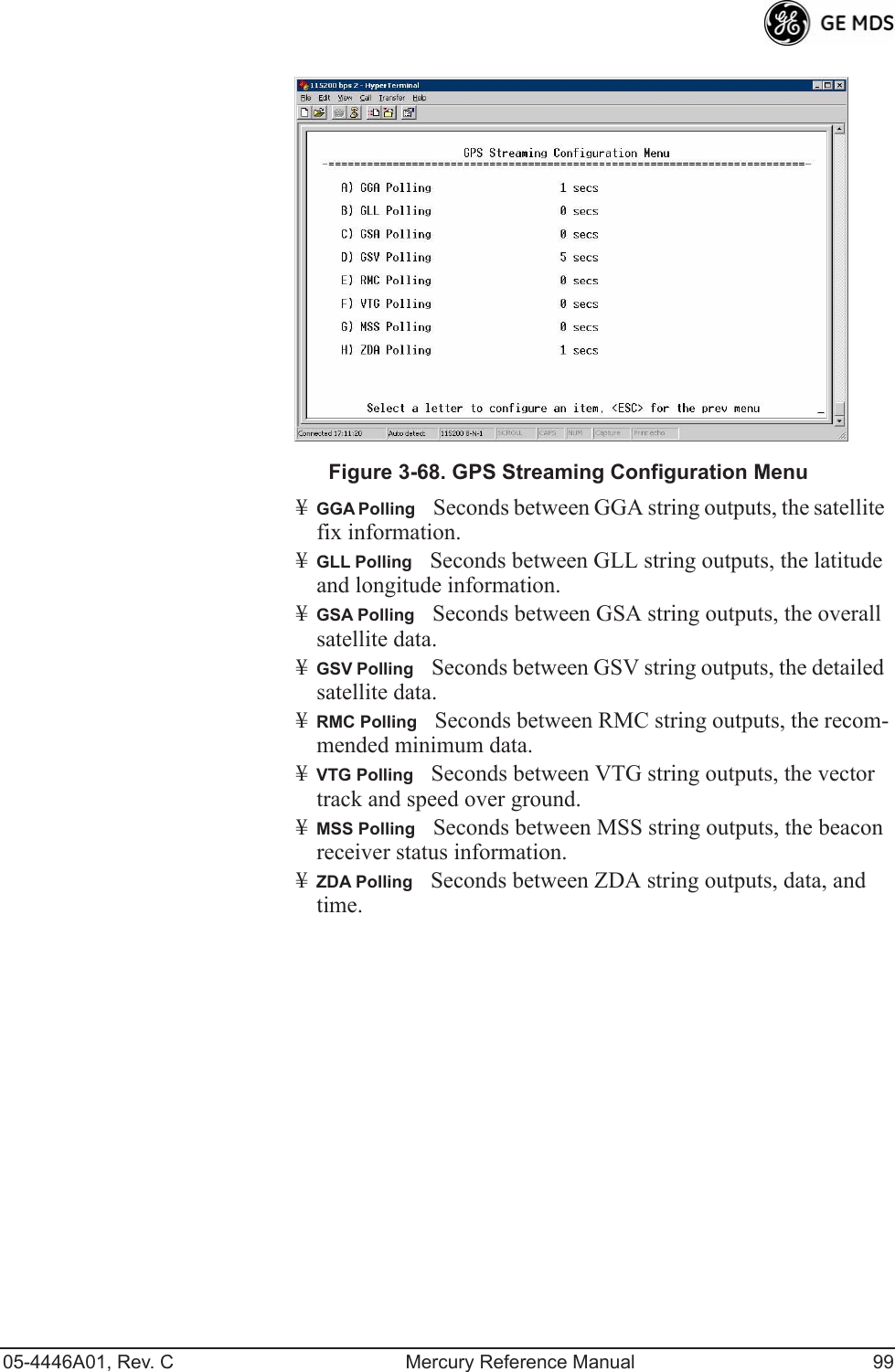
![98 Mercury Reference Manual 05-4446A01, Rev. C¥Maximum Receive ErrorsSelect this item to change the maxi-mum allowable number of receive errors. When the number of errors exceeds this number, a redundancy switchover occurs. [0-1000; 500]3.9 GPS CONFIGURATION (REMOTE ONLY)This menu allows you to view or set important parameters for the built-in Global Positioning System (GPS) receiver in the Mercury Remote.Invisible place holderFigure 3-67. GPS Configuration Menu (Remote Only)¥Stream GPS to ConsoleUsed to enable/disable streaming of GPS NMEA data to the console port (COM1). Baud rate is 4800 baud when Stream GPS to console is enabled.[enabled, disabled; disabled]¥GPS to Console Baud RateThe serial baud rate when GPS streaming is enabled.¥Send GPS via UDPUsed to enable/disable sending GPS NMEA data to a server via UDP. [enabled, disabled; disabled]¥GPS UDP Server IP AddressSpecify the destination address for GPS NMEA UDP packets. [any valid IP address; 0.0.0.0]¥GPS UDP Server UDP PortDestination UDP port for GPS NMEA UDP packets. [valid UDP port number; 0]¥GPS Streaming ConfigurationA submenu for setting GPS NMEA outputs. (See Figure 3-68 on Page 99.)](https://usermanual.wiki/GE-MDS/DS-MERCURY3650.Revised-user-manual-2-of-3/User-Guide-1008947-Page-44.png)
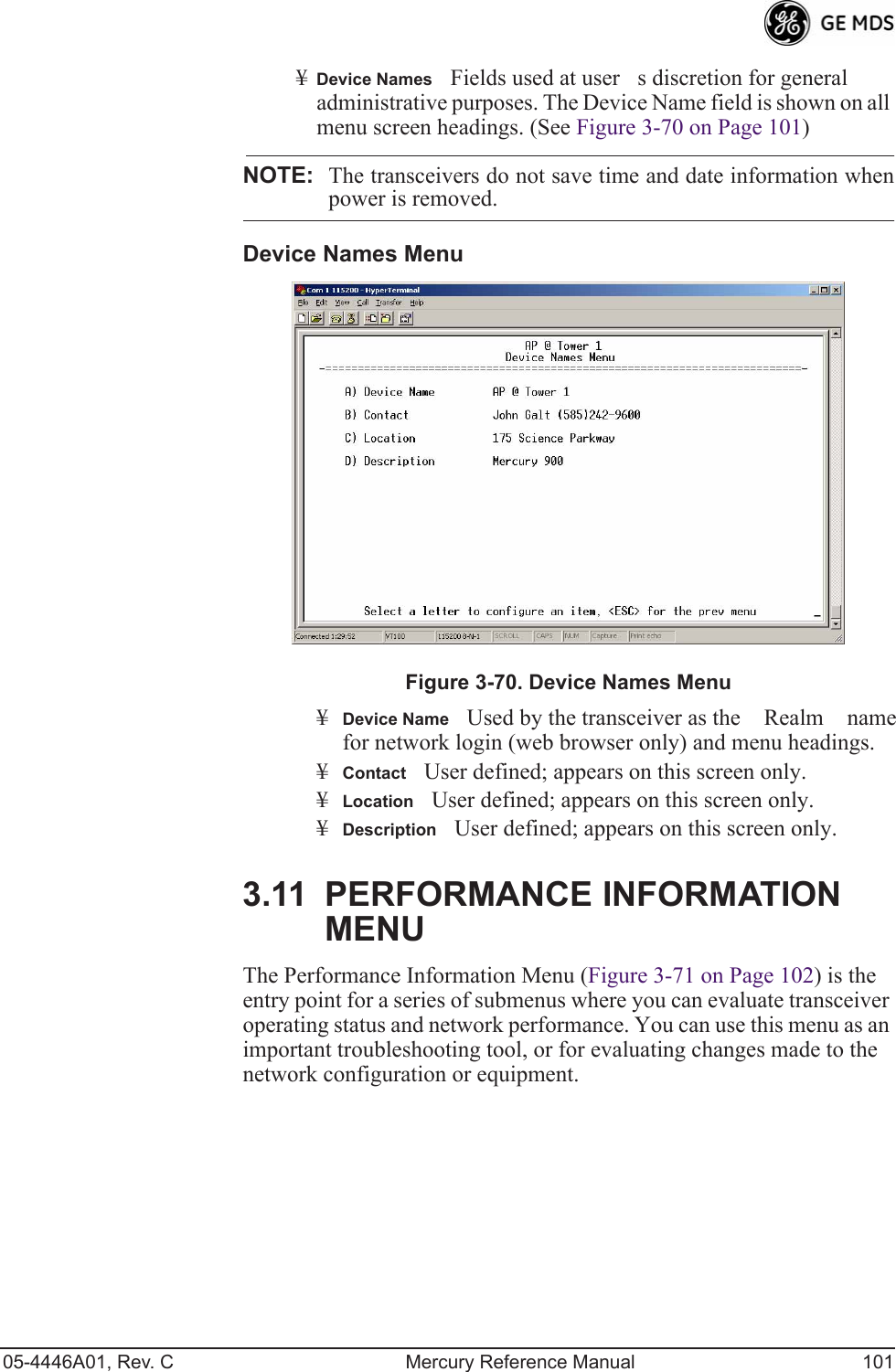
![100 Mercury Reference Manual 05-4446A01, Rev. C3.10 DEVICE INFORMATION MENUFigure 3-69 shows the menu that displays basic administrative data on the unit to which you are connected. It also provides access to user-spe-cific parameters such as date/time settings and device names.Figure 3-69. Device Information Menu¥Model (Display only)¥Serial Number (Display only)¥Uptime (Display only)Elapsed time since boot-up.¥DateCurrent date being used for the transceiver logs. User-set-able. (Value lost with power failure if SNTP [Simple Network Time Protocol] server not accessible.) ¥TimeCurrent time of day. User-setable. Setting: HH:MM:SS (Value lost with power failure if SNTP server not accessible.)¥Date FormatSelect presentation format:¥ Generic = dd Mmm yyyy¥ European = dd-mm-yyyy¥ US = mm-dd-yyyy¥Console Baud RateUsed to set/display data communications rate (in bits-per-second) between a connected console terminal and the radio. [115200]¥UTC Time OffsetSet/view the number of hours difference between your local clock time and Universal Coordinated Time. Offsets for U.S. times zones are shown in the chart below.Time Zone (U.S.)UTC Offset (Hours)PST -8MST -7CST -6EST -5](https://usermanual.wiki/GE-MDS/DS-MERCURY3650.Revised-user-manual-2-of-3/User-Guide-1008947-Page-46.png)
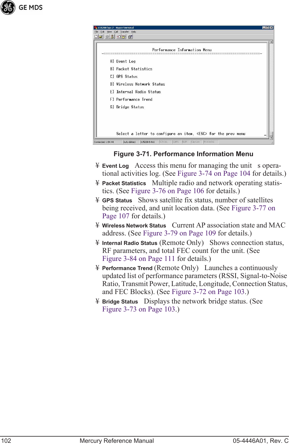
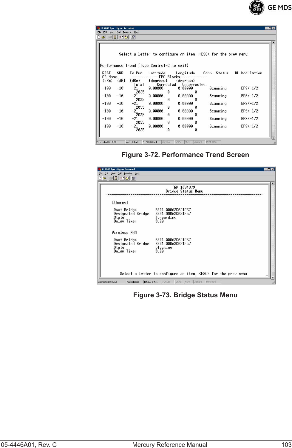
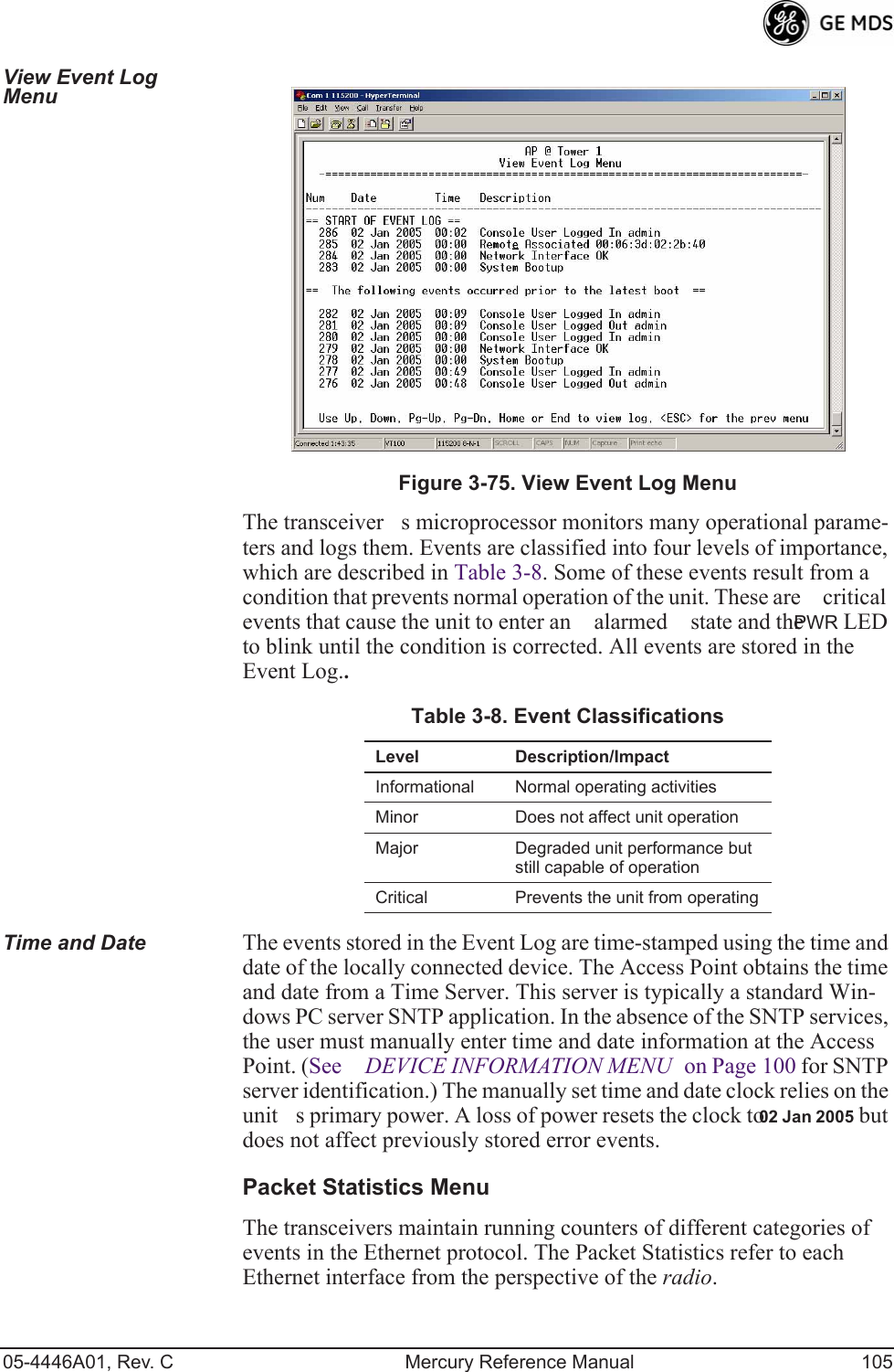
![104 Mercury Reference Manual 05-4446A01, Rev. CEvent Log Menu Invisible place holderFigure 3-74. Event Log Menu¥Current AlarmsShows active alarms (if any) reported by the transceiver.¥View Event LogDisplays a log of radio events arranged by event number, date, and time. (Example shown in Figure 3-75 on Page 105).¥Clear Event LogErases all previously logged events.¥Send Event LogSends the event log to the server. You must answer the challenge question Send File? y/n before the request proceeds.¥Event Log Host AddressSet/display the IP address of the TFTP server. [any valid IP address; 0.0.0.0]¥Event Log FilenameSet/display the name of the event log file on the TFTP server. [any valid filename; eventlog.txt]¥Transfer OptionsA menu for configuring the TFTP transfer.¥Syslog Server AddressUse this selection to set or view the IP address of the Syslog server. Syslog is a standardized protocol for sending IP log data across a network. Low cost (or even free) Syslog downloads are available online by searching for the term Syslog Server. [any valid IP address; 0.0.0.0]](https://usermanual.wiki/GE-MDS/DS-MERCURY3650.Revised-user-manual-2-of-3/User-Guide-1008947-Page-50.png)
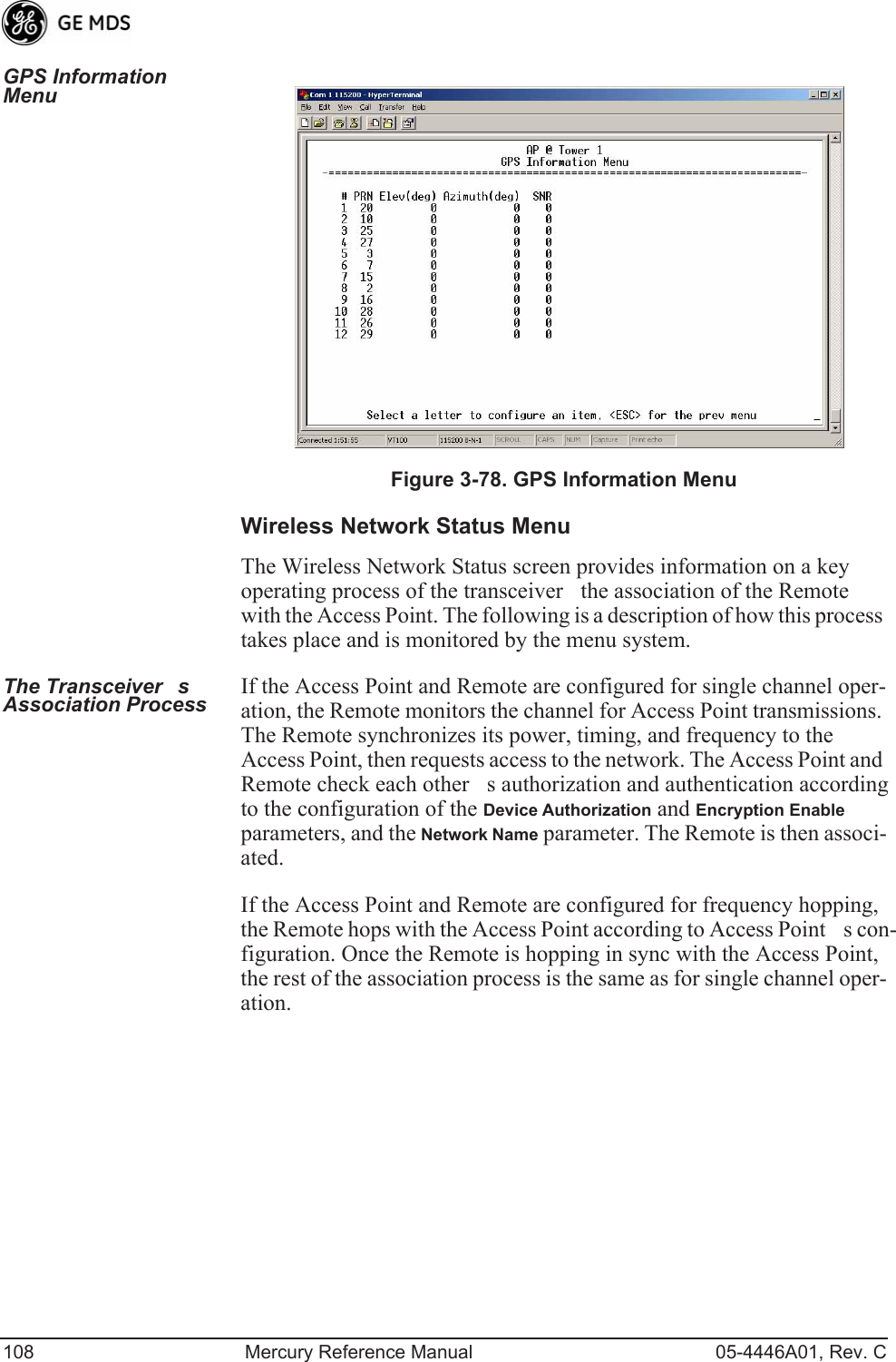
![05-4446A01, Rev. C Mercury Reference Manual 107GPS Status Menu Invisible place holderFigure 3-77. GPS Status Menu¥GPS Serial NumberThe serial number of the GPS unit in the radio.¥GPS Firmware VersionThe firmware version running on the GPS chip.¥Satellite Fix StatusIndicates whether or not the unit has achieved signal lock with the minimum required number of GPS satellites. The transceiver requires a fix on five satellites to achieve Precise Positioning Service (PPS) and four to maintain PPS. [No Fix, Fix]¥Number of SatellitesShows the number of GPS satellites received by the transceiver. Although there are typically 24 active GPS satellites orbiting the Earth twice a day, only a sub-set of these is visible to a receiver at a given location. A good signal provides information from six to ten satellites.¥LatitudeShows the transceivers latitudinal location (in degrees), based on GPS data received from the satellites.¥LongitudeShows the transceivers longitudinal location (in degrees), based on GPS data received from the satellites.¥AltitudeShows the transceivers altitude above sea level (in feet), based on GPS data received from the satellites.¥GPS InformationShows data about the individual satellites being received, including the Pseudo-Random Noise (PRN) code (a unique bit stream for each satellite), the satellites ele-vation (in degrees), azimuth (in degrees), and the sig-nal-to-noise ratio of the carrier signal (SNR). Figure 3-78 on Page 108 shows a layout example for this screen.](https://usermanual.wiki/GE-MDS/DS-MERCURY3650.Revised-user-manual-2-of-3/User-Guide-1008947-Page-53.png)
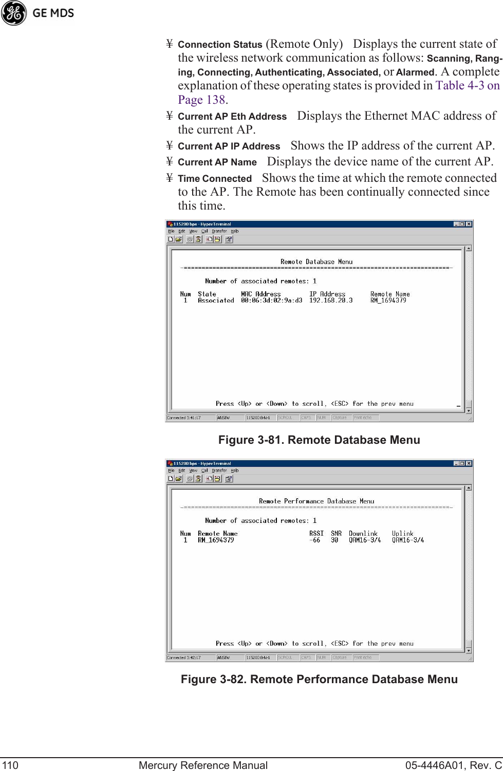
![05-4446A01, Rev. C Mercury Reference Manual 109Invisible place holderFigure 3-79. Wireless Network Status Menu (AP)Invisible place holderFigure 3-80. Wireless Network Status Menu (Remote)¥Device StatusDisplays the overall operating condition of the transceiver. [Operational, Alarmed]¥Associated Remotes (AP Only)Shows the number of Remote transceivers currently associated with the AP.¥PA TemperatureShows the power amplifier temperature in degrees Celsius.¥Remote Database (AP Only)Displays a submenu where associ-ated Remotes are listed in table form according to their number, operational state, MAC address, IP address, and name (if assigned). (See Figure 3-81 on Page 110.)¥Remote Performance Database (AP Only)Displays a submenu where associated Remote performance data is listed in table form. Remotes are presented according to their number, MAC address, RSSI, SNR, modulation type, uplink modulation, and FEC total. (See Figure 3-82 on Page 110.)](https://usermanual.wiki/GE-MDS/DS-MERCURY3650.Revised-user-manual-2-of-3/User-Guide-1008947-Page-55.png)
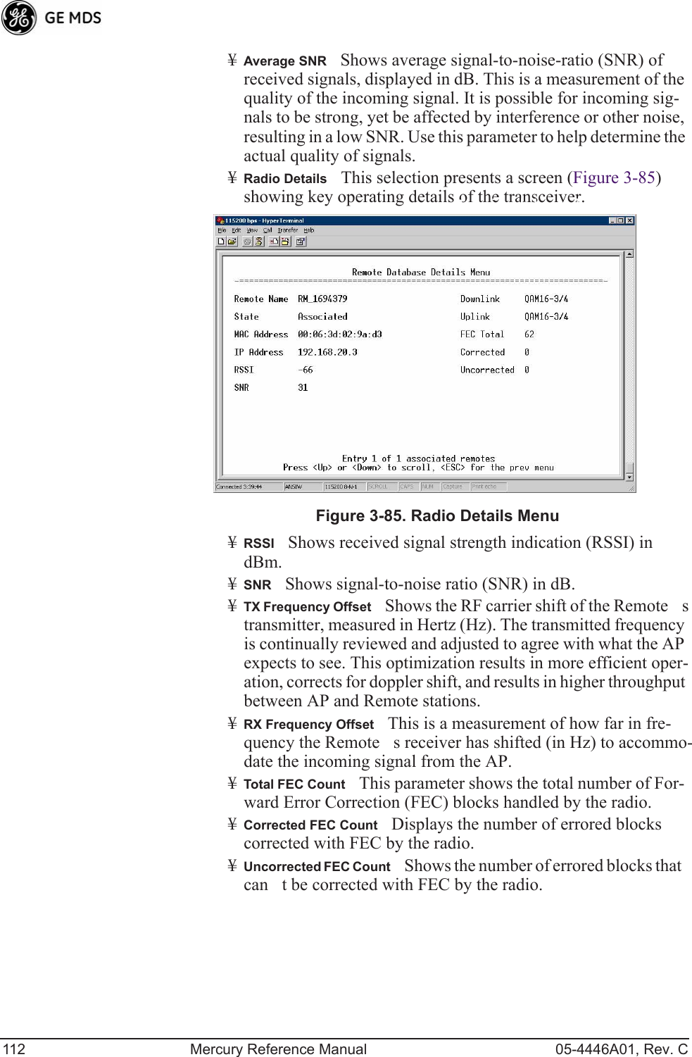
![05-4446A01, Rev. C Mercury Reference Manual 111Invisible place holderFigure 3-83. Remote Database Details Menu (AP)Internal Radio Status Menu (Remote Only)Invisible place holderFigure 3-84. Internal Radio Status (Remote Only)¥Connection StatusIndicates whether or not the Remote station has associated with an AP. [Associated, Scanning, Ranging, Con-necting, Authorizing]¥Current AP NameShows the Device Name of the current AP.¥Transmit PowerShows the RF power output from the transmit-ter. The AP changes the transmit power of the Remote to match the desired receive power at the APs receiver. This provides end-to-end power control.¥Average RSSIShows average received signal strength indica-tion (RSSI) of incoming RF signals, displayed in dBm.](https://usermanual.wiki/GE-MDS/DS-MERCURY3650.Revised-user-manual-2-of-3/User-Guide-1008947-Page-57.png)
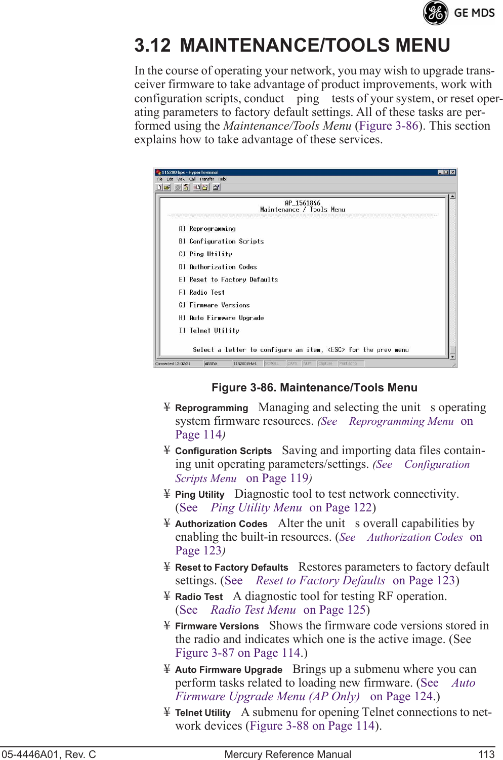
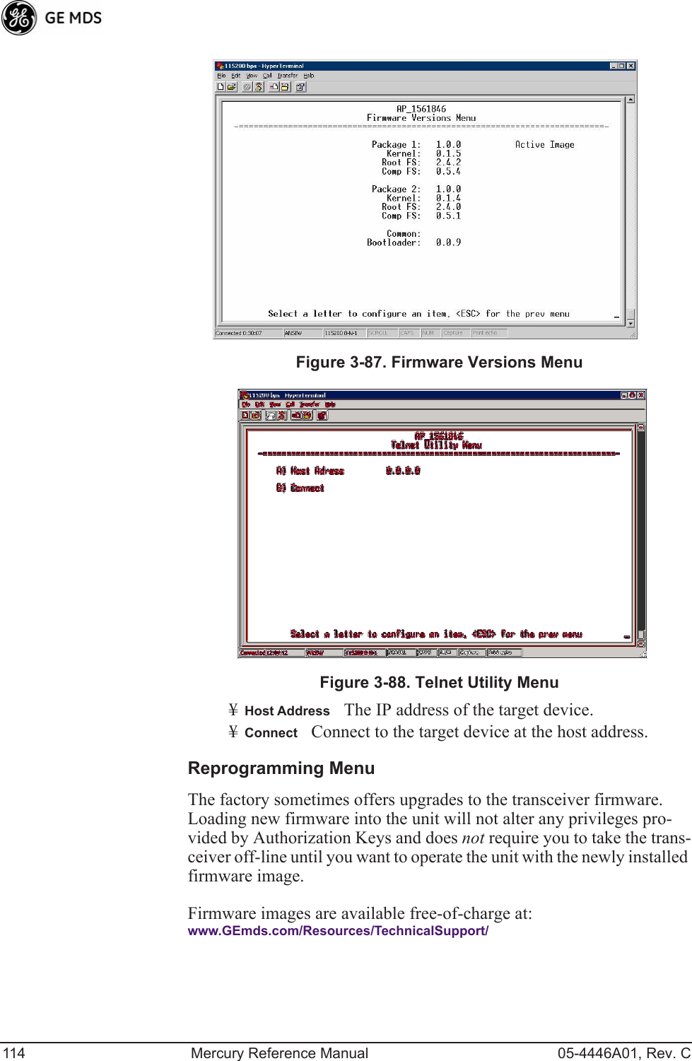
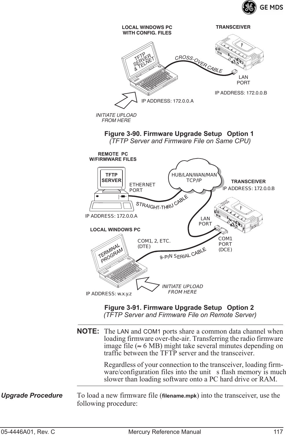
![05-4446A01, Rev. C Mercury Reference Manual 115NOTE: Firmware for AP radios is different than for Remotes, and maynot be interchanged. This was only true for earlier (pre-2.1.0)firmware.NOTE: Always read the release notes for downloaded firmware. Thesenotes contain important information on compatibility and anyspecial steps needed for proper installation.All units and versions have two resident images. Version 1.4.4 had two .mpk files, one for the Access Point and one for the Remote. As of ver-sion 2.1.0, there is only one .mpk file which you can use with both Access Points and Remotes.The transceiver has two copies of the firmware (microprocessor code) used for the operating system and applications. One copy is active and the second is standing by, ready to be used once activated. You can load new firmware into the inactive position and place it in service whenever you desire.Invisible place holderFigure 3-89. Reprogramming Menu¥TFTP Host AddressIP address of the host computer from which to get the file. [Any valid IP address] This same IP address is used in other screens/functions (reprogramming, logging, etc.). Changing it here also changes it for other screens/functions.¥Firmware FilenameName of file to be received by the TFTP server. [Any 40-character alphanumeric string] Verify that this cor-responds to the TFTP directory location. May require sub-direc-tory, for example: me-bkrc-2_1_0.mpk.¥Transfer OptionsA menu for configuring the TFTP transfer.¥Retrieve FileInitiates the file transfer from the TFTP server. The new file is placed into inactive firmware image. [Y, N ]¥Image VerifyInitiate the verification of the integrity of firmware file held in unit.](https://usermanual.wiki/GE-MDS/DS-MERCURY3650.Revised-user-manual-2-of-3/User-Guide-1008947-Page-61.png)