GE MDS DS-MERCURY3650 Wireless IP/Ethernet Transceiver User Manual Book1
GE MDS LLC Wireless IP/Ethernet Transceiver Book1
GE MDS >
Contents
- 1. User manual
- 2. Revised user manual 1 of 3
- 3. Revised user manual 2 of 3
- 4. Revised user manual 3 of 3
Revised user manual 1 of 3

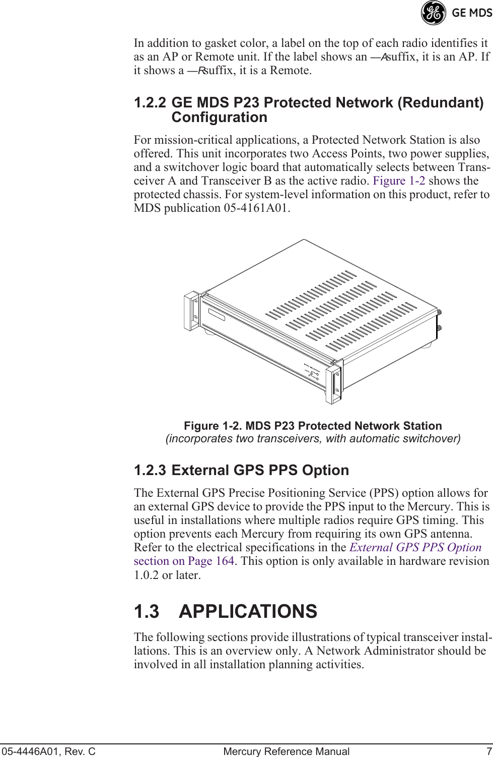
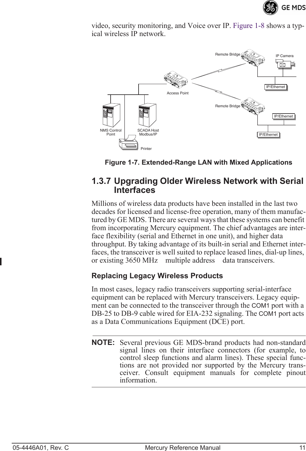
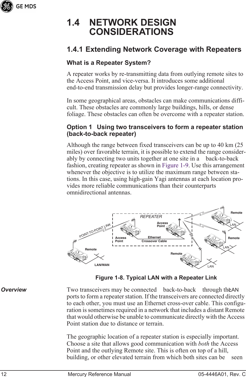
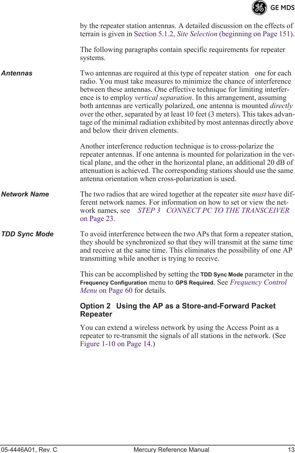
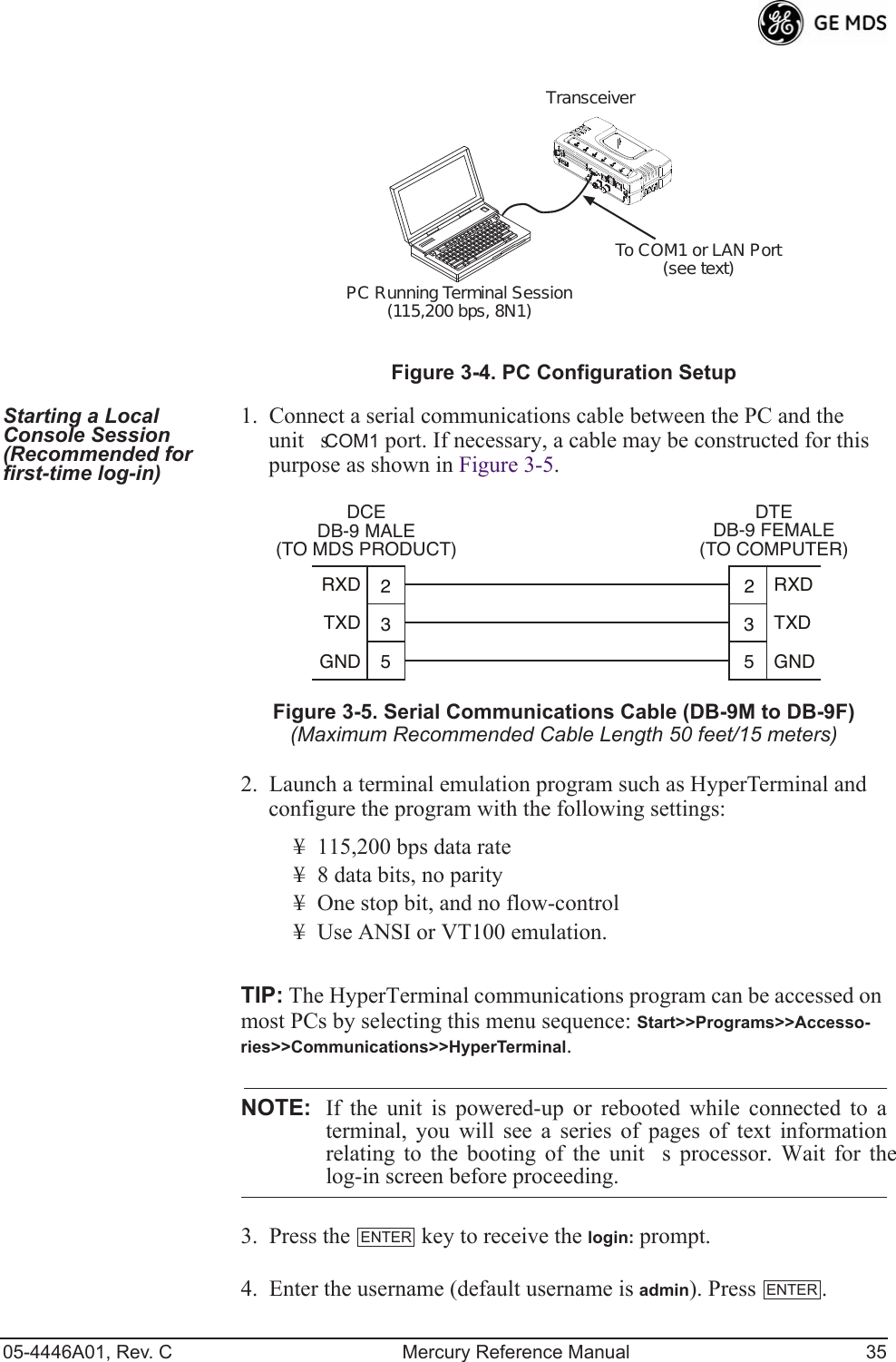
![05-4446A01, Rev. C Mercury Reference Manual 3 1.1 ABOUT THIS MANUAL This Reference Manual is one of two publications provided for users of the Mercury Series TM transceiver system. It contains detailed product information, an overview of common applications, a screen-by-screen review of the menu system, technical specifications, suggested settings for various scenarios, and detailed troubleshooting information. This manual should be available to all personnel responsible for network design, setup, commissioning and troubleshooting. 1.1.1 Start-Up Guide The Mercury Series Start-Up Guide (Part No. 05-4558A01) is a com-panion publication to the Reference Manual. It is a smaller book, with a specific purpose—to guide an installer in the basic steps for getting a transceiver on the air and communicating with other units in a network. It provides only the essential information installers require for getting their equipment up and running in the shortest time possible. 1.1.2 Online Access to Manuals In addition to printed manuals, many users need access to documents electronically. This is especially useful when you need to access docu-mentation while traveling, or want to share a document with another user in the field. Electronic documents also allow searching for a spe-cific term or subject, especially in larger manuals.Access manuals for our equipment anytime from our Web site at www.GEmds.com. Simply click the Downloads tab at the top of the home page and select Product Manuals from the drop-down list. A search window appears to help you locate the manual you need.Online manuals are provided as PDF files in the Adobe® Acrobat® stan-dard. If necessary, download the free reader for PDF files from www.adobe.com.1.1.3 Conventions Used in This ManualOn-Screen Menu ItemsOn-screen menu items or command entries are presented in a distinctive font to set them apart from regular text (for example: Network Name, IP Address, Password). You will find this font most often in Chapter 3, where the menu system is discussed in detail. When variable settings or a range of options are available for a menu option, the items are pre-sented inside brackets, with the default setting (if any) shown last after a semicolon:[available settings or range; default setting]](https://usermanual.wiki/GE-MDS/DS-MERCURY3650.Revised-user-manual-1-of-3/User-Guide-1008946-Page-11.png)
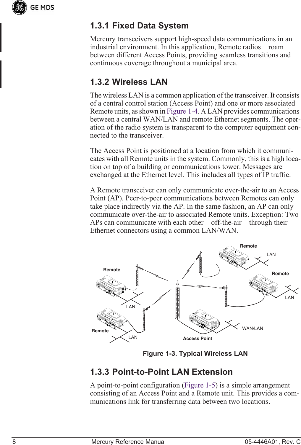
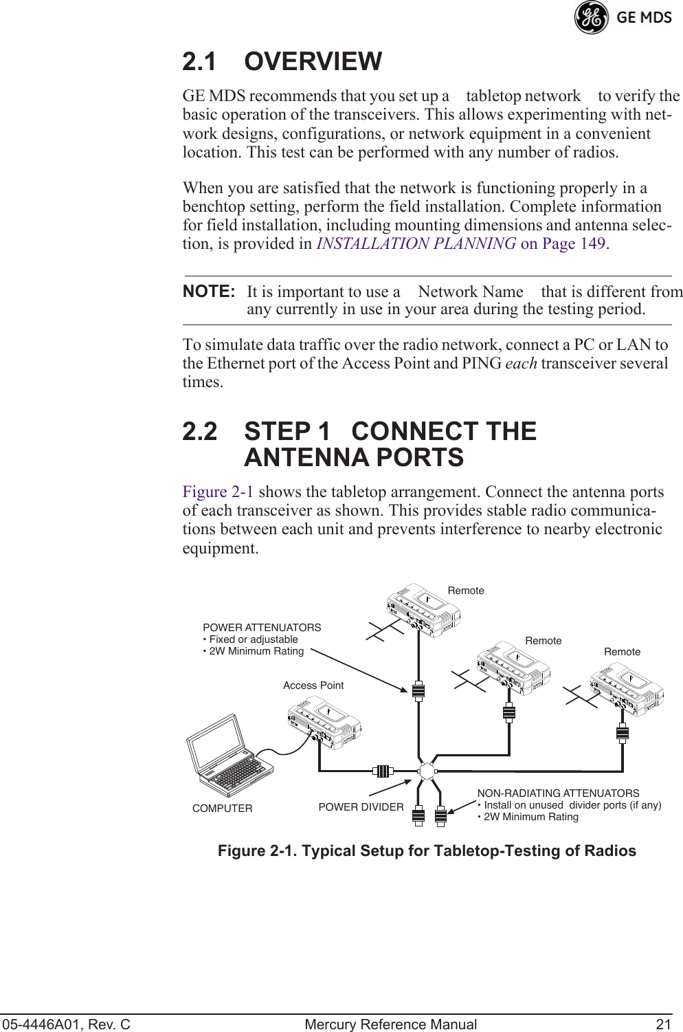
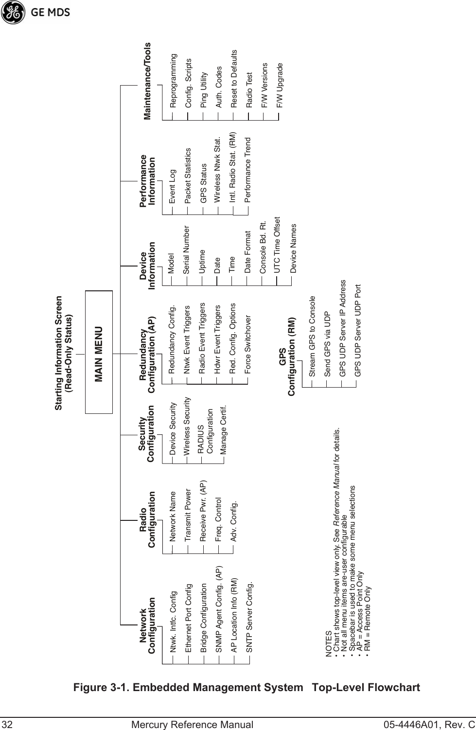
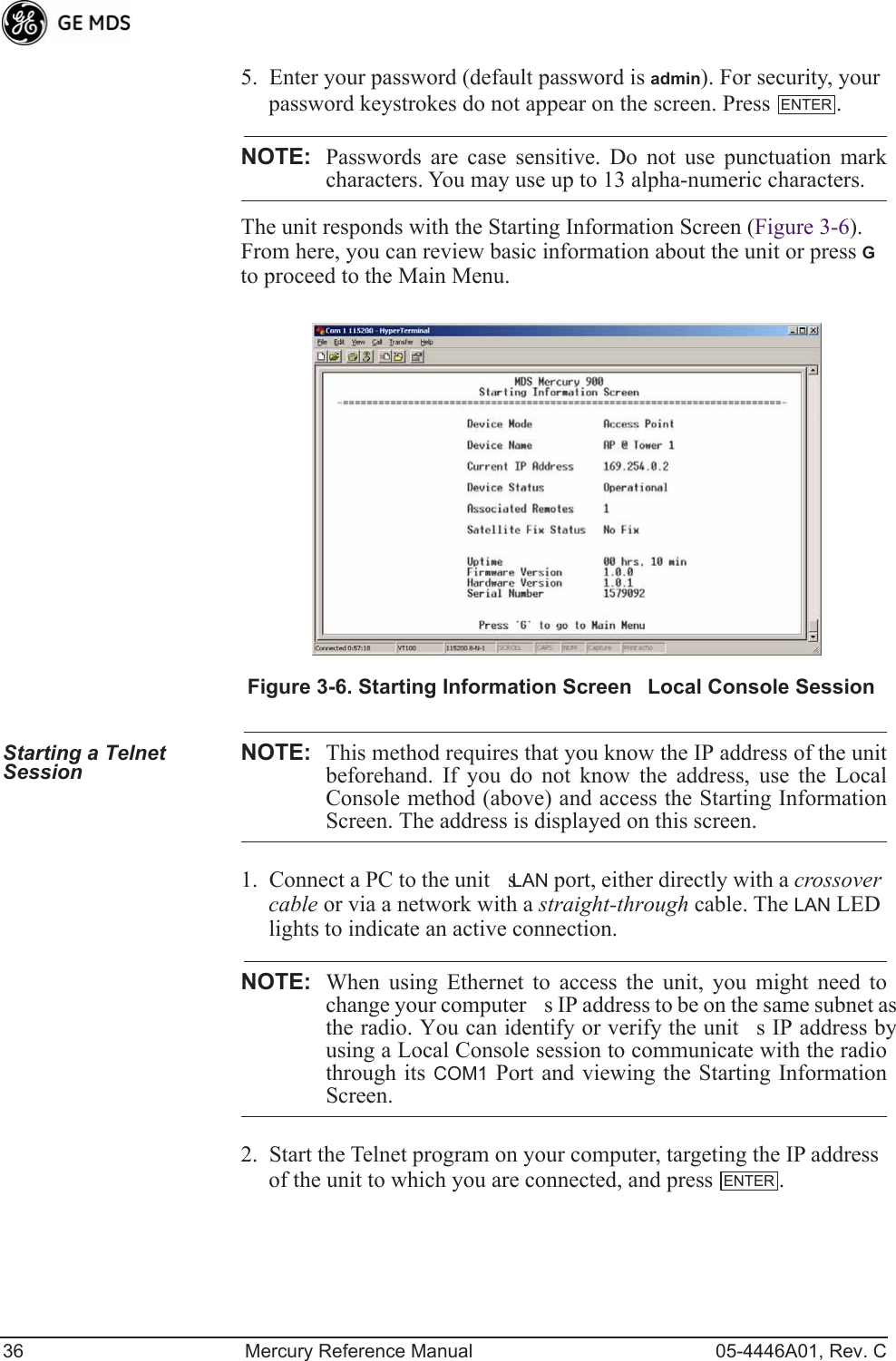
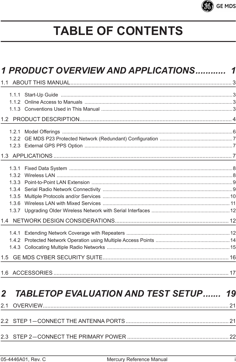
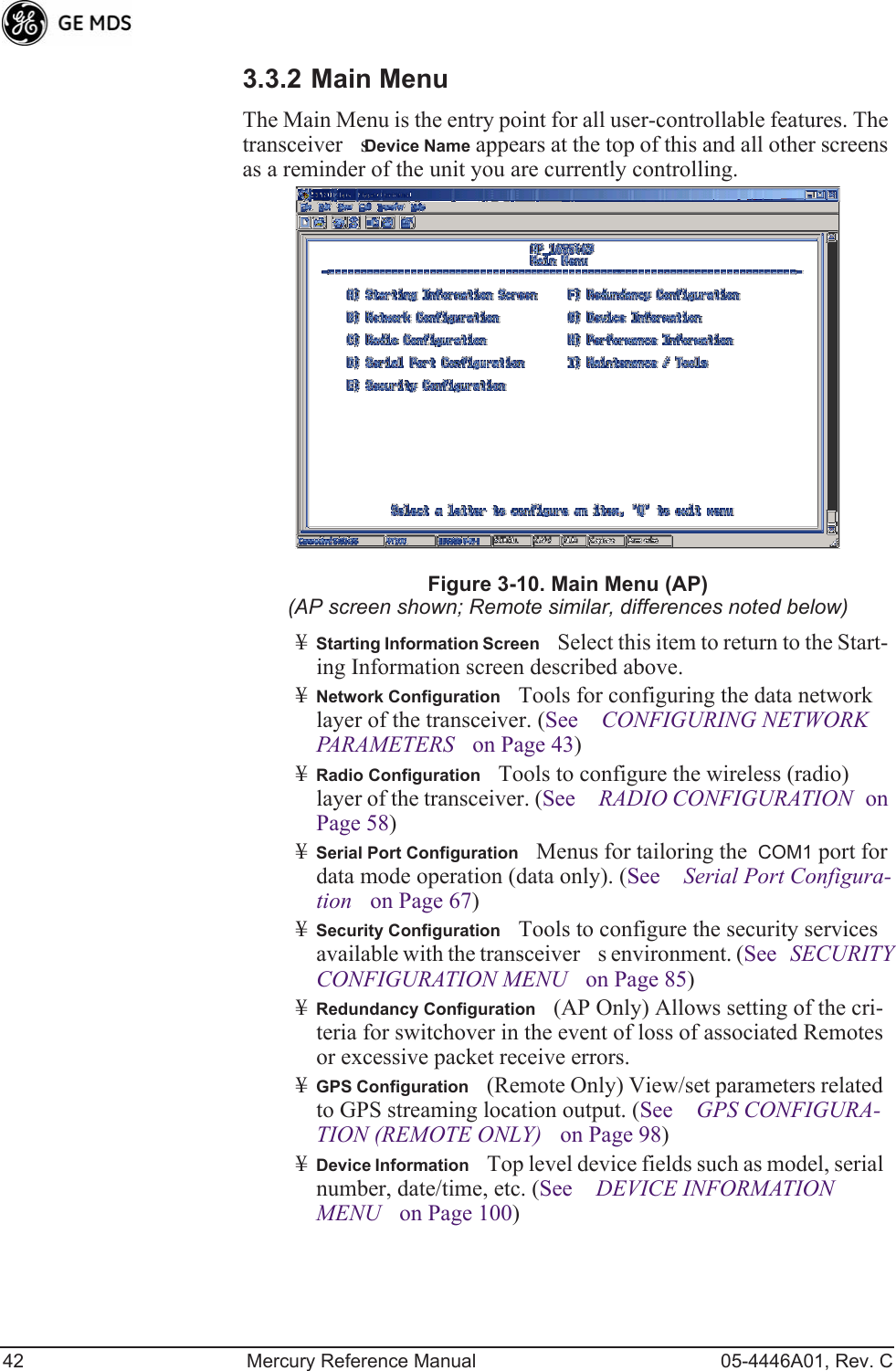
![40 Mercury Reference Manual 05-4446A01, Rev. CNOTE: In the menu descriptions that follow, parameter options/range,and any default values are displayed at the end of the textbetween square brackets. Note that the default setting isalways shown after a semicolon: [available settings or range; default setting]3.3 BASIC OVERVIEW OF OPERATION3.3.1 Starting Information ScreenOnce you have logged into the Management System, the Starting Infor-mation Screen (Figure 3-9) appears with an overview of the transceiver and its current operating conditions. Figure 3-9. Starting Information Screen(AP screen shown; Remote similar, differences noted below)¥Device ModeOperating mode of the unit as it relates to the radio network.¥Device NameThis is a user-defined parameter that appears in the heading of all pages. (To change it, see Network Configura-tion Menu on Page 43.)¥Current IP AddressUnits IP address [169.254.0.2]¥Device StatusCondition of the units operation as follows:At Access Point:¥OperationalUnit operating normally.¥InitializingThis is the first phase after boot-up.¥SynchronizingUnit is waiting for the GPS receiver to obtain a satellite fix and for its internal clock to synchronize to the GPS timing signals.](https://usermanual.wiki/GE-MDS/DS-MERCURY3650.Revised-user-manual-1-of-3/User-Guide-1008946-Page-48.png)
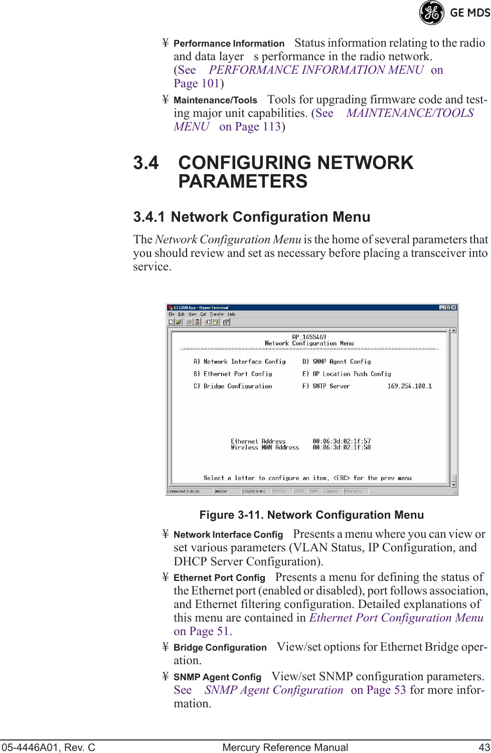
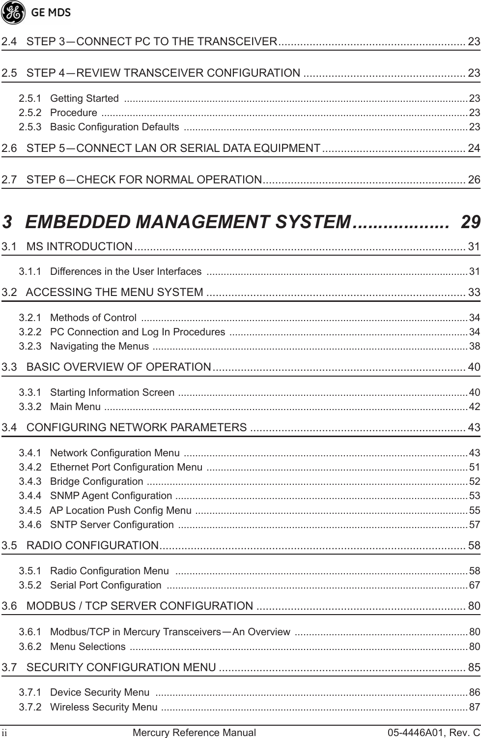
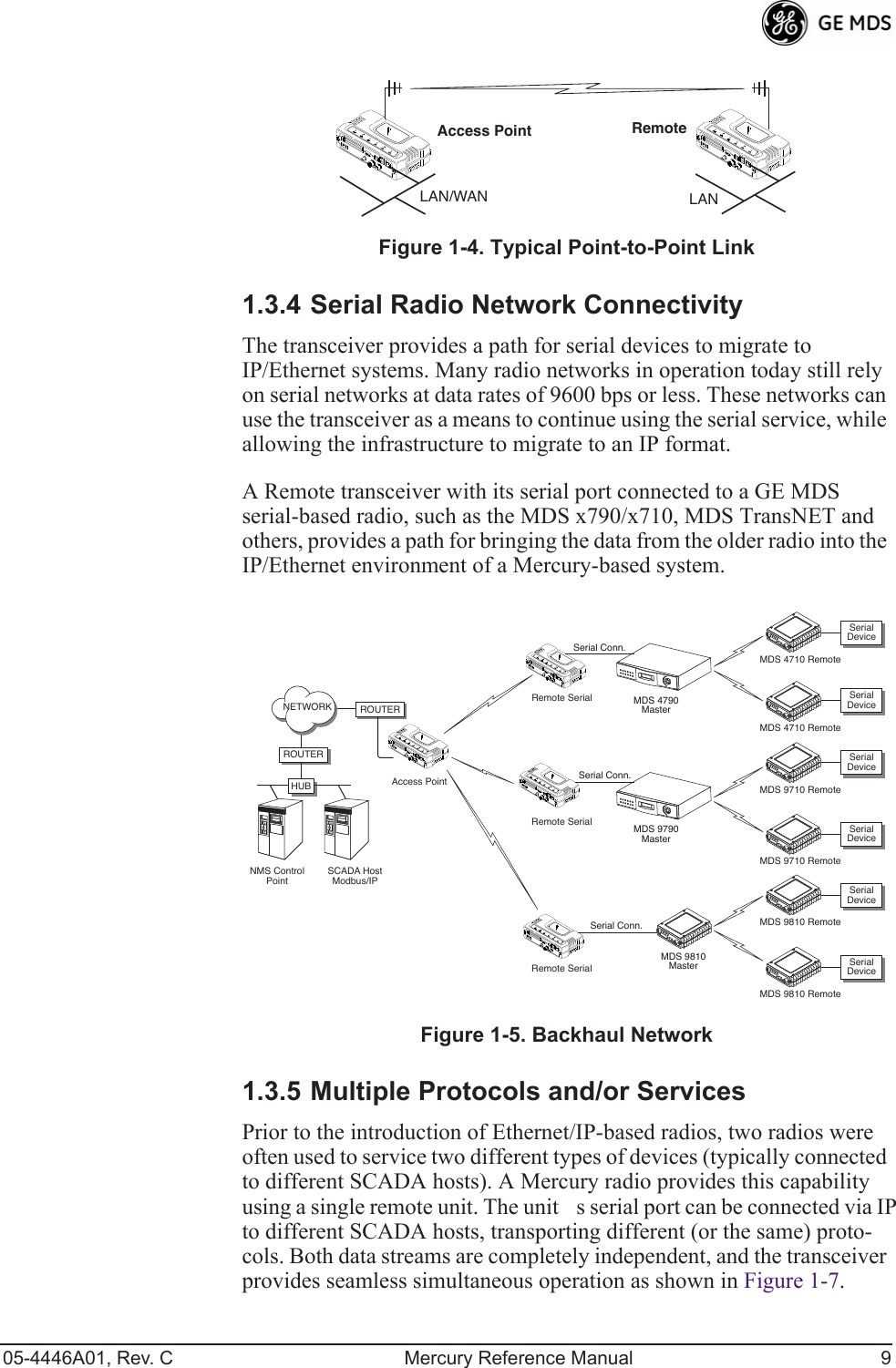
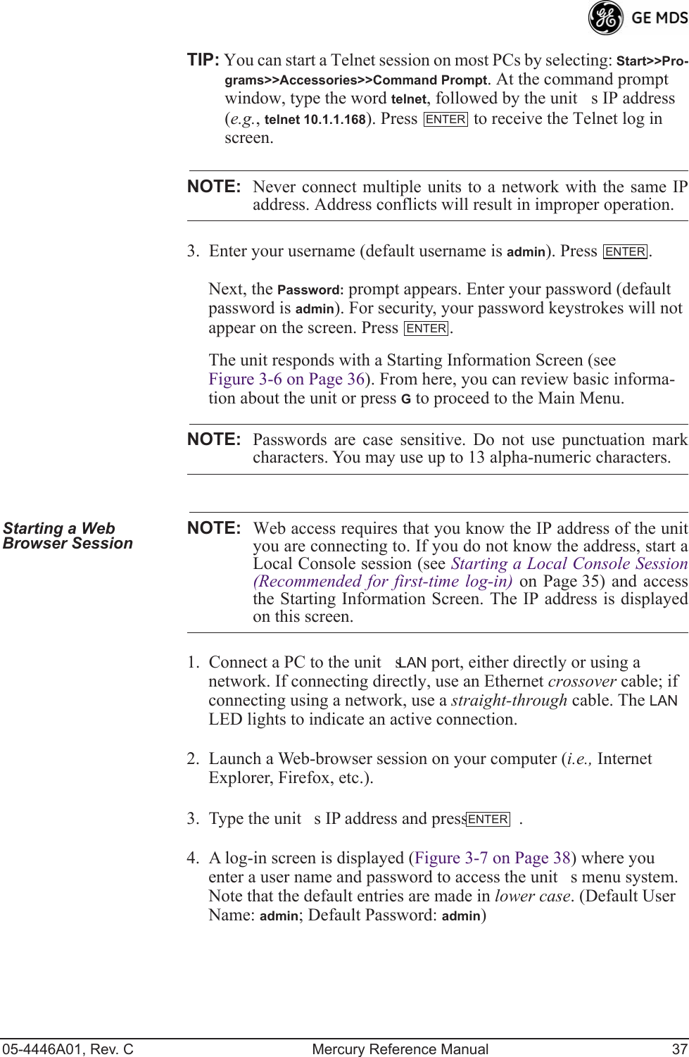
![44 Mercury Reference Manual 05-4446A01, Rev. C¥AP Location Push ConfigPresents a submenu for configuring an AP to automatically force connected remotes to receive the AP Locations file from the AP. See AP Location Push Config Menu on Page 55 for details.¥SNTP ServerAddress of SNTP server (RFC 2030) from which the transceiver will automatically get the time-of-day. You can also manually set the date and time. A Mercury unit tries to get the time and date from the SNTP server only if an IP address is configured. It will continue to retry every minute until it suc-ceeds. The transceivers use UTC (Universal Time Coordinated) with a configurable time offset. [0]NOTE: The Mercury gets time of day data from the GPS receiver if thereceiver gets a satellite fix.Network Interface Configuration SubmenuInvisible place holderFigure 3-12. Network Interface Configuration Submenu¥VLAN StatusThis selection is used to enable or disable virtual LAN operation. For details, refer to VLAN Configuration Menu on Page 45. [enable, disabled; disabled]¥IP ConfigurationThis selection presents a submenu for config-uring the local IP address of the transceiver. Detailed explana-tions are provided in the section titled IP Configuration Menu on Page 50.¥DHCP Server ConfigMenu for configuration of DHCP services by the Access Point. DHCP provides on-the-fly IP address assignments to other LAN devices, including Mercury Series units. For details, refer to DHCP Server Configuration (Data and Mgmt) on Page 48.](https://usermanual.wiki/GE-MDS/DS-MERCURY3650.Revised-user-manual-1-of-3/User-Guide-1008946-Page-52.png)
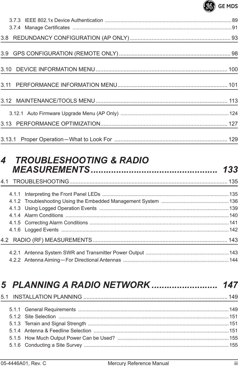
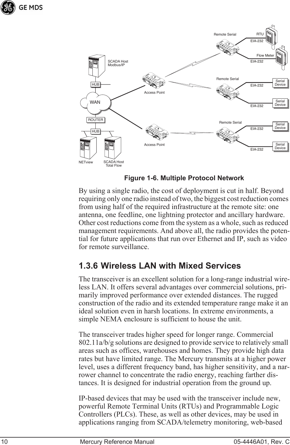
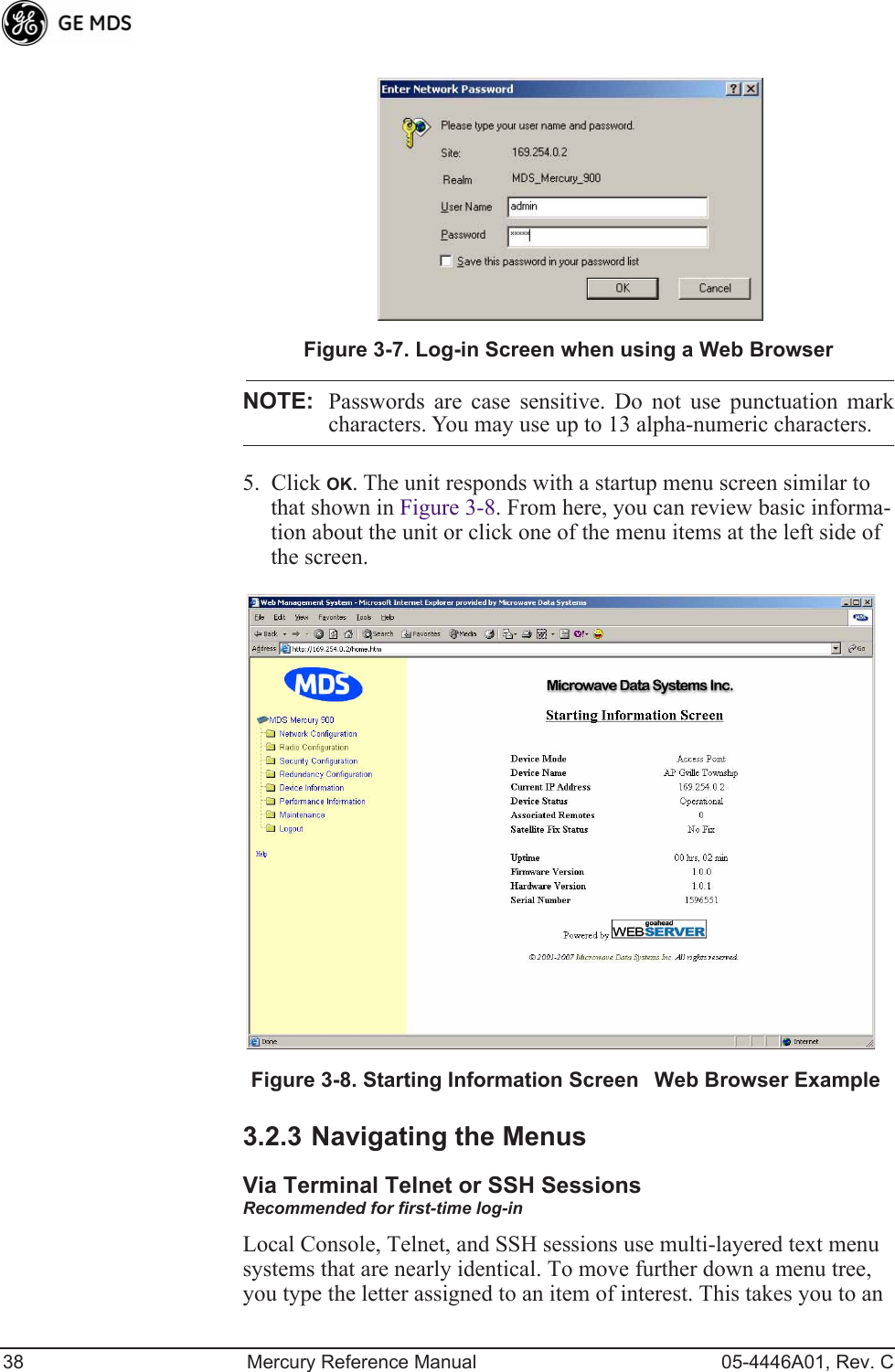
![46 Mercury Reference Manual 05-4446A01, Rev. CNetwork Interface Configuration MenuVLAN ItemsInvisible place holderFigure 3-13. VLAN Configuration Menu¥VLAN StatusDefines whether the radio handles Ethernet frames in extended 802.1Q mode or in normal mode in the Ethernet port. If configured with a trunk port, the Mercury passes all tagged traffic regardless of the VLAN ID. The Mer-cury only uses the Data VLAN ID parameter when the ETH port is configured as an Access Port.[enabled, disabled; disabled]¥VLAN Ethport ModeDefines if the Ethernet port acts as a trunk port or as an access port. Auto mode defines the port as a trunk port in an AP, or an access port in a Remote radio. [Auto, Trunk, Access; Auto]¥Management VLAN IDDefines the VLAN ID for traffic directed to the radio itself, other than the terminal server process. This VLAN ID is used for filtering and for tagging purposes. [1-4094; 2]¥Data VLAN IDDefines the VLAN ID assigned to traffic directed to and from the Ethernet port and the terminal server process in the radio. This VLAN ID is used for filtering and tagging pur-poses. [1-4094; 3]¥Default Route IFDefines the VLAN that contains the default gateway in the radio. [MGMT, DATA; MGMT]¥Management VLAN ModeApplies the VLAN tag to management frames. [Tagged, Native; Tagged].¥Management VLAN Subnet ConfigPresents a screen where you can set the IP Address Mode, Static IP Address, and Static IP Netmask (see Figure 3-14 on Page 47).¥DHCP Server Config (Mgmt)Presents a screen where you can view or set the DHCP server status and address information for management functions (see Figure 3-15 on Page 48).](https://usermanual.wiki/GE-MDS/DS-MERCURY3650.Revised-user-manual-1-of-3/User-Guide-1008946-Page-54.png)
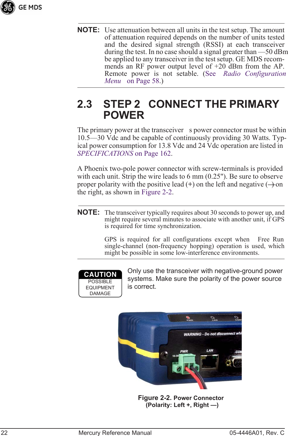
![05-4446A01, Rev. C Mercury Reference Manual 47¥Data VLAN Subnet ConfigPresents a screen where you can view or set the IP mode and address information (see Figure 3-17 on Page 49).¥DHCP Server Config (Data)Presents a screen where you can view or set DHCP server status and address information for data functions (see Figure 3-16 on Page 49).Management VLAN Subnet Configuration MenuInvisible place holderFigure 3-14. Management VLAN Subnet Configuration MenuNOTE: Changes to any of the following parameters while communi-cating over the network (LAN or over-the-air) might cause aloss of communication with the unit you are configuring. Youmust re-establish communication using the new IP address.¥IP Address ModeDefines the source of the IP address of this device. Only static IP addressing mode is available when VLAN Status is enabled. [Static, Dynamic; Static]¥Static IP AddressThe IPv4 local IP address. [ 192.168.1.1]¥Static IP NetmaskThe IPv4 local subnet mask. This value is used when the radio attempts to send a locally initiated message, either from the terminal server, or from a management process. [255.255.0.0]The lower three lines of the screen (Current IP Address, Current IP Netmask, Current IP Gateway) show the current addressing configured at the trans-ceiver. Current IP Gateway only displays on this screen if Default Route IF on the Network Interface Config menu (Figure 3-13 on Page 46) is set to Management.Selecting option I from the menu in Figure 3-13 on Page 46 displays the screen shown in Figure 3-17 on Page 49. Note that the IP address is dif-ferent even though it is the same physical unit. This is because this IP address is defined for a different VLAN.](https://usermanual.wiki/GE-MDS/DS-MERCURY3650.Revised-user-manual-1-of-3/User-Guide-1008946-Page-55.png)
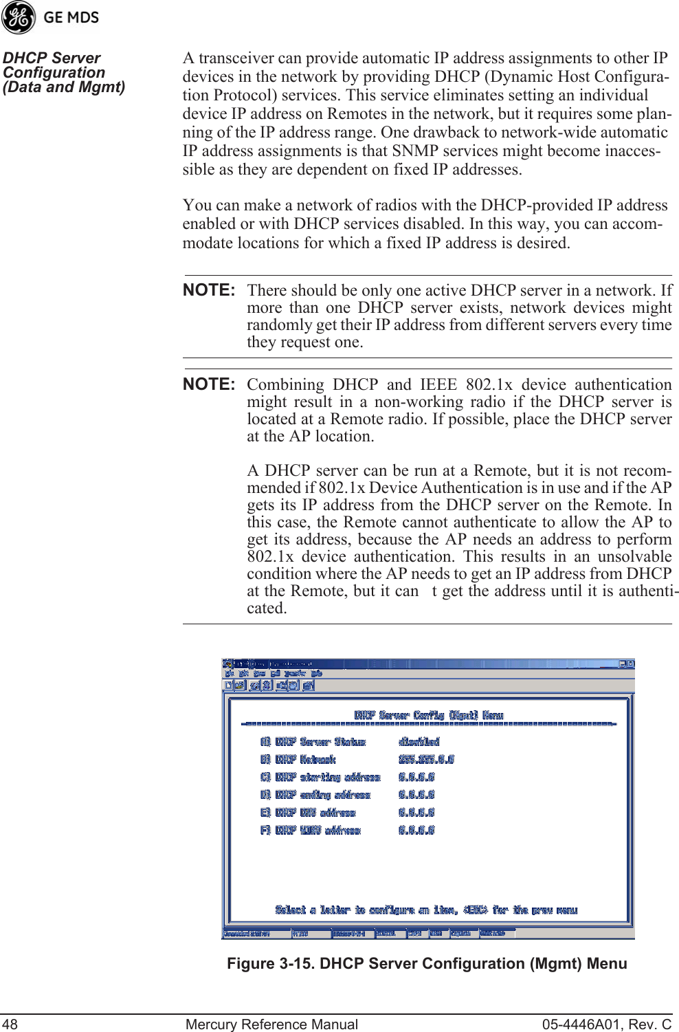
![05-4446A01, Rev. C Mercury Reference Manual 49Invisible place holderFigure 3-16. DHCP Server Configuration (Data) Menu¥DHCP Server StatusEnable/Disable the response to DHCP requests to assign an IP address. [Disabled/Enabled; Disabled]¥DHCP NetmaskIP netmask to be assigned along with the IP address in response to a DHCP request. [0.0.0.0]¥DHCP starting addressLowest IP address in the range of addresses provided by this device. [0.0.0.0]¥DHCP ending addressHighest IP address in the range of addresses provided by this device. A maximum of 256 addresses is allowed in this range. [0.0.0.0]¥DHCP DNS addressDomain Name Server address provided by this service.¥DHCP WINS addressWindows Internet Naming Service server address provided by this service.Data VLAN Subnet Configuration Menu Invisible place holderFigure 3-17. Data VLAN Subnet Configuration Menu](https://usermanual.wiki/GE-MDS/DS-MERCURY3650.Revised-user-manual-1-of-3/User-Guide-1008946-Page-57.png)
![50 Mercury Reference Manual 05-4446A01, Rev. C¥IP Address ModeDefines the source of this devices IP address. Only static IP addressing mode is available when VLAN Status is enabled [Static; Static]¥IP AddressThe IPv4 local IP address. [ 192.168.1.1]¥IP NetmaskThe IPv4 local subnet mask. This value is used when the radio attempts to send a locally initiated message, from either the terminal server or the management process. [255.255.0.0]¥IP GatewayThe IPv4 address of the default gateway device, typically a router. [0.0.0.0]The lower three lines of the screen (Current IP Address, Current IP Netmask, and Current IP Gateway) show the current addressing configured at the transceiver. Current IP Gateway only displays on this screen if Default Route IF on the Network Interface Config menu (Figure 3-13 on Page 46) is set to Data.Invisible place holderIP Configuration MenuFigure 3-18. IP Configuration MenuCAUTION: Changes to the following parameters while communicatingover the network (LAN or over-the-air) might cause a loss ofcommunication with the unit being configured. You mustre-establish communication using the new IP address.¥IP Address ModeDefines the source of this devices IP address. [Static, Dynamic; Static]¥Static IP Address (User Review Recommended)Essential for connec-tivity to the transceivers MS using the LAN port. Enter any valid IP address that is unique within the network. This field is unnec-essary if DHCP is enabled. [192.168.1.1]](https://usermanual.wiki/GE-MDS/DS-MERCURY3650.Revised-user-manual-1-of-3/User-Guide-1008946-Page-58.png)
![05-4446A01, Rev. C Mercury Reference Manual 51¥Static IP NetmaskThe IPv4 local subnet mask. This field is unnecessary if DHCP is enabled. [255.255.0.0]¥Static IP GatewayThe IPv4 address of the network gateway device, typically a router. This field is unnecessary if DHCP is enabled. [0.0.0.0]The lower three items on the screen (Current IP Address, Net-mask and Gateway) show the actual addressing at the trans-ceiver whether it was obtained from static configuration or from a DHCP server.3.4.2 Ethernet Port Configuration MenuThe transceiver allows for special control of the Ethernet interface, to allow traffic awareness and availability of the backhaul network for redundancy purposes.NOTE: The transceivers network port supports 10BaseT and100BaseT connections. Confirm that your hub/switch iscapable of auto-switching data rates.To prevent excessive Ethernet traffic from degrading perfor-mance, place the transceiver in a segment, or behind routers.Figure 3-19. Ethernet Port Configuration Menu¥Ethernet Port EnableAllows enabling/disabling Ethernet traffic for security purposes. Setting it to enabled enables the port. [enabled, disabled; enabled]¥Ethernet Port Phy RateThe Ethernet ports configured speed.¥Eth Port Follows Association (Remote Only)When enabled, the Ethernet port is disabled when not associated. [enabled, disabled; disabled]](https://usermanual.wiki/GE-MDS/DS-MERCURY3650.Revised-user-manual-1-of-3/User-Guide-1008946-Page-59.png)
![52 Mercury Reference Manual 05-4446A01, Rev. C¥Ethernet Filtering ConfigAllows enabling/disabling filtering and specifying of Ethernet addresses.Ethernet Filtering Configuration MenuInvisible place holderFigure 3-20. Ethernet Filtering Configuration Menu¥Enable FilteringActivates Ethernet filtering.[enabled, disabled; disabled]¥Address 1, 2, 3, 4Ethernet address fields. When filtering is enabled, the Mercury only accepts traffic on its Ethernet port from the configured addresses. [Valid IP address string]3.4.3 Bridge Configuration Invisible place holderFigure 3-21. Bridge Configuration Menu¥Bridge PriorityView/set the priority of the bridge in the span-ning tree. [0-65535; 32769]](https://usermanual.wiki/GE-MDS/DS-MERCURY3650.Revised-user-manual-1-of-3/User-Guide-1008946-Page-60.png)
![05-4446A01, Rev. C Mercury Reference Manual 53¥Bridge Hello TimeView/set spanning tree hello time. This parameter affects how often the bridge sends a spanning tree Bridge Protocol Data Unit (BPDU). [1-10 seconds; 2 seconds]¥Bridge Forward DelayView/set spanning tree forwarding delay. Affects how long the bridge spends listening and learning after initialization. [4-30 seconds; 5 seconds].3.4.4 SNMP Agent ConfigurationThe transceiver contains over 100 custom SNMP-manageable objects as well as the IETF standard RFC1213 for protocol statistics, also known as MIB II. You can use off-the-shelf SNMP managers to access the transceivers SNMP Agents MIB, such as Castle Rock Computing SNMPc“ and Hewlett Packard OpenView“. The transceivers SNMP agent supports SNMPv1, v2, and v3.The objects are split into nine MIB files for use with your SNMP man-ager. There are textual conventions, common files, and specific files. This allows the flexibility to change areas of the MIB and not affect other existing installations or customers.¥msdreg.mibMDS sub-tree registrations¥mds_comm.mibMDS Common MIB definitions for objects and events common to the entire product family¥mercury_reg.mibMDS sub-tree registrations¥mercurytrv1.mibSNMPv1 enterprise-specific traps¥mercurytrv2.mibSNMPv2 enterprise-specific traps¥mercury_comm.mib MIB definitions for objects and events common to the entire Mercury Series¥mercury_ap.mibMIB definitions for objects and events for an Access Point transceiver¥mercury_rem.mibDefinitions for objects and events for a Remote radio¥mercury_sec.mibFor security management of the radio systemNOTE: SNMP management requires that the proper IP address,network, and gateway addresses are configured in each associ-ated network transceiver. In addition, some management systems might require that youcompile the MIB files in the order shown above.](https://usermanual.wiki/GE-MDS/DS-MERCURY3650.Revised-user-manual-1-of-3/User-Guide-1008946-Page-61.png)
![54 Mercury Reference Manual 05-4446A01, Rev. CInvisible place holderFigure 3-22. SNMP Server Configuration MenuThis menu provides configuration and control of vital SNMP functions.¥Read Community StringSNMP community name with SNMPv1/SNMPv2c read access. This string can contain up to 30 alpha-numeric characters.¥Write Community StringSNMP community name with SNMPv1/SNMPv2c write access. This string can contain up to 30 alpha-numeric characters.¥Trap Community StringSNMP community name with SNMPv1/SNMPv2c trap access. This string can contain up to 30 alpha-numeric characters.¥V3 Authentication PasswordAuthentication password stored in flash memory. This is used when the Agent is managing pass-words locally (or initially for all cases on reboot). This is the SNMPv3 password used for Authentication (currently, only MD5 is supported). This string can contain up to 30 alpha-numeric characters.¥V3 Privacy PasswordPrivacy password stored in flash memory. Used when the SNMP Agent is managing passwords locally (or initially for all cases on reboot). This is the SNMPv3 password used for privacy (DES encryption). This string can contain between 8 and 30 alpha-numeric characters.¥SNMP ModeThis specifies the mode of operation of the radios SNMP Agent. The choices are: disabled, v1_only, v2_only, v3_only, v1-v2, and v1-v2-v3. If the mode is disabled, the Agent does not respond to any SNMP traffic. If the mode is v1_only, v2_only, or v3_only, the Agent responds only to that version of SNMP traffic. If the mode is v1-v2 or v1-v2-v3, the Agent responds to the specified version of SNMP traffic. [v1-v2-v3]](https://usermanual.wiki/GE-MDS/DS-MERCURY3650.Revised-user-manual-1-of-3/User-Guide-1008946-Page-62.png)