GE MDS DS-EL806 EL806 OEM Transnet User Manual Book2
GE MDS LLC EL806 OEM Transnet Book2
UserManual.wiki
>
GE MDS
>
DS-EL806 User Manual
>
User Manual
Contents
1.
users manual
2.
Host User Manual
3.
User Manual
User Manual
Navigation menu
Upload a User Manual
Namespaces
Wiki Guide
HTML
PDF
Info
Views
User Manual
Discussion / Help
Navigation
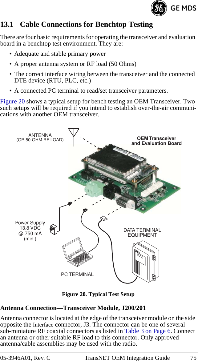
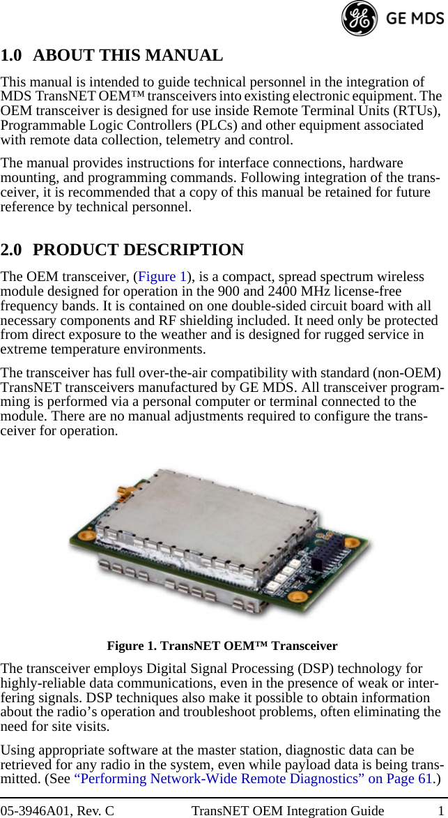
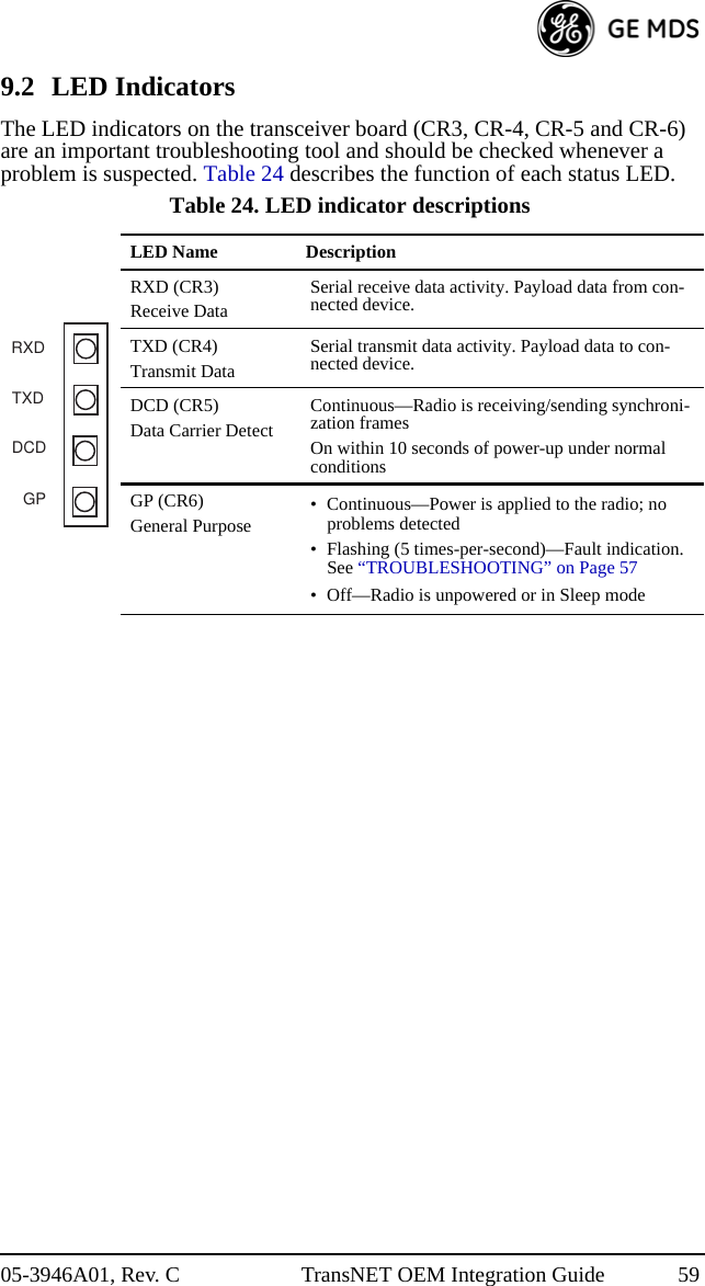
![05-3946A01, Rev. C TransNET OEM Integration Guide iiiEntering Commands ................................................................... 358.3 Detailed Command Descriptions ................................................ 41ADDR [1–65000] ....................................................................... 41AMASK [0000 0000–FFFF FFFF] ............................................ 42AT [ON, OFF] ............................................................................ 42ASENSE [HI/LO]....................................................................... 42BAUD [xxxxx abc] .................................................................... 42BAND [A, B, C]......................................................................... 43BUFF [ON, OFF] ....................................................................... 43CODE [NONE, 1…255] ............................................................ 43CSADDR [1–65000, NONE] ..................................................... 44CTS [0–255] ............................................................................... 44CTSHOLD [0–60000]................................................................ 44DEVICE [DCE, CTS KEY] ...................................................... 45DLINK [xxxxx/ON/OFF]........................................................... 45DKEY......................................................................................... 45DTYPE [NODE/ROOT] ............................................................ 46FEC [ON, OFF].......................................................................... 46HOPTIME [7, 28]....................................................................... 46INIT ............................................................................................ 46HREV ......................................................................................... 48KEY............................................................................................ 48LED [ON, OFF] ......................................................................... 48LPM [1, 0] .................................................................................. 48LPMHOLD [0–1000] ................................................................. 49MODE [M, R, X] ....................................................................... 49MRSSI [NONE, –40...–90] ........................................................ 49OT [ON, OFF]............................................................................ 50OWM [xxxxx] ............................................................................ 50OWN [xxxxx]............................................................................. 50PORT [RS232, RS485]............................................................... 50PWR [20–30].............................................................................. 50REPEAT [0–10].......................................................................... 51RETRY [0–10] ........................................................................... 51RSSI............................................................................................ 51RTU [ON, OFF, 0-80] ................................................................ 52RX [xxxx]................................................................................... 52RXD [0–255].............................................................................. 52RXTOT [NONE, 0–1440].......................................................... 52](https://usermanual.wiki/GE-MDS/DS-EL806.User-Manual/User-Guide-1465711-Page-5.png)
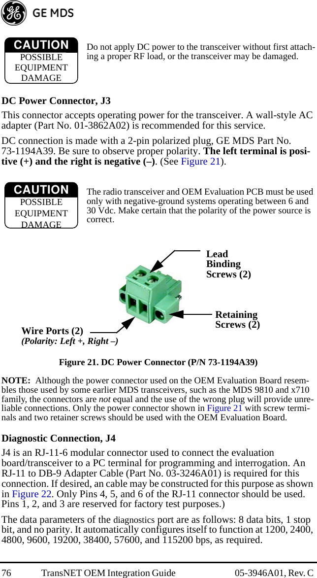
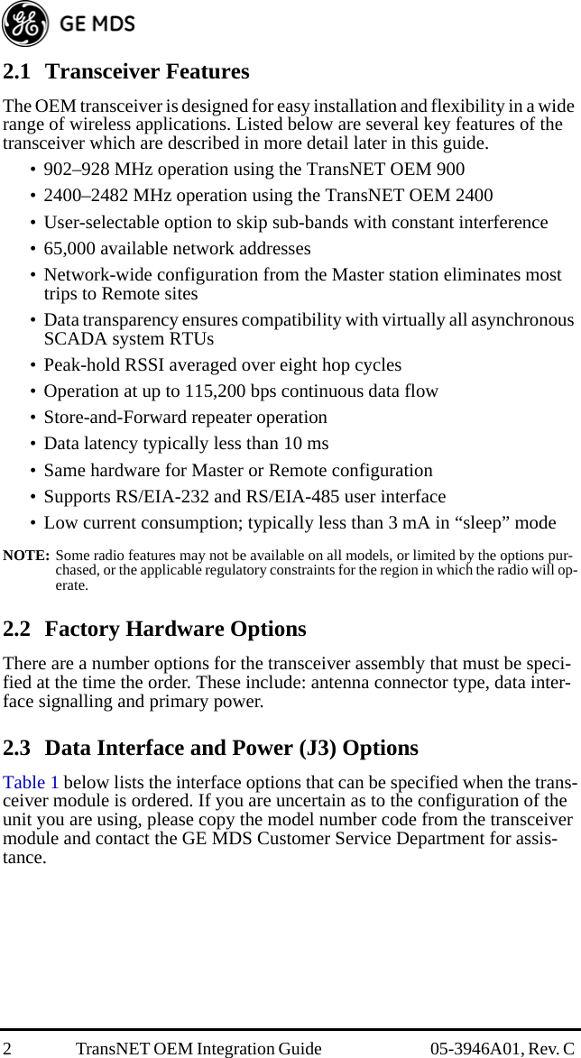
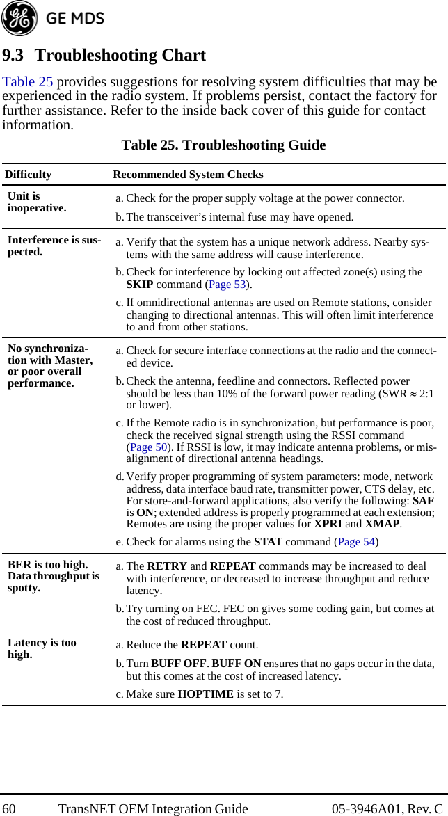
![iv TransNET OEM Integration Guide 05-3946A01, Rev. C SAF [ON, OFF] .......................................................................... 53SETUP ........................................................................................ 53SER............................................................................................. 53SHOW CON............................................................................... 53SHOW PWR............................................................................... 54SHOW SYNC............................................................................. 54SKIP [NONE, 1...8].................................................................... 54SLEEP [ON, OFF]...................................................................... 55SREV.......................................................................................... 55STAT ........................................................................................... 55TEMP.......................................................................................... 56TX [xxxx] ................................................................................... 56UNIT [10000–65000] ................................................................. 56XADDR [0–31] .......................................................................... 56XMAP [00000000-FFFFFFFF].................................................. 56XPRI [0–31] ............................................................................... 57XRSSI [NONE, –40...–120] ....................................................... 57ZONE CLEAR ........................................................................... 57ZONE DATA .............................................................................. 57Checking for Alarms—STAT command .................................... 58Major Alarms versus Minor Alarms........................................... 59Alarm Codes’ Definitions........................................................... 599.2 LED Indicators ............................................................................ 609.3 Troubleshooting Chart ................................................................ 61Saving a Web-Site Firmware File Onto Your PC ....................... 63Using the I/O Points with InSite™ NMS Software.................... 73Application Example—Digital Input/Output at Remote ............ 73Evaluation PC Board .................................................................. 74Connecting the Transceiver & Evaluation Board....................... 75Antenna Connection—Transceiver Module, J200/201 .............. 76DC Power Connector, J3 ............................................................ 77Diagnostic Connection, J4.......................................................... 77DATA Connector, J5................................................................... 78Transceiver Power Interface, J1 ................................................. 80Assembly Drawing ..................................................................... 81Parts List..................................................................................... 81Evaluation PCB Interface to Transceiver PCB, J2 ..................... 83PCB Schematic........................................................................... 83](https://usermanual.wiki/GE-MDS/DS-EL806.User-Manual/User-Guide-1465711-Page-6.png)
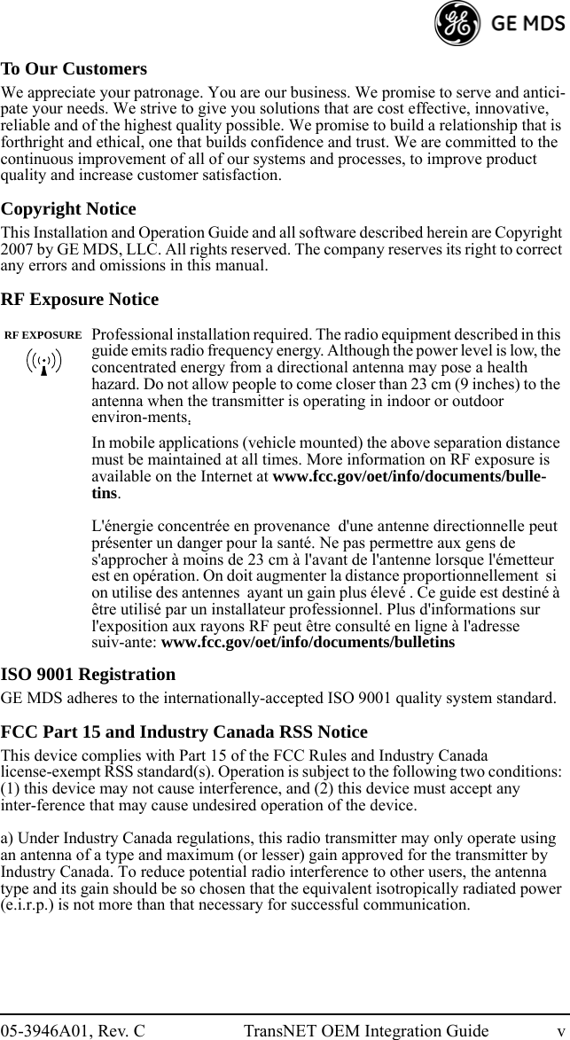
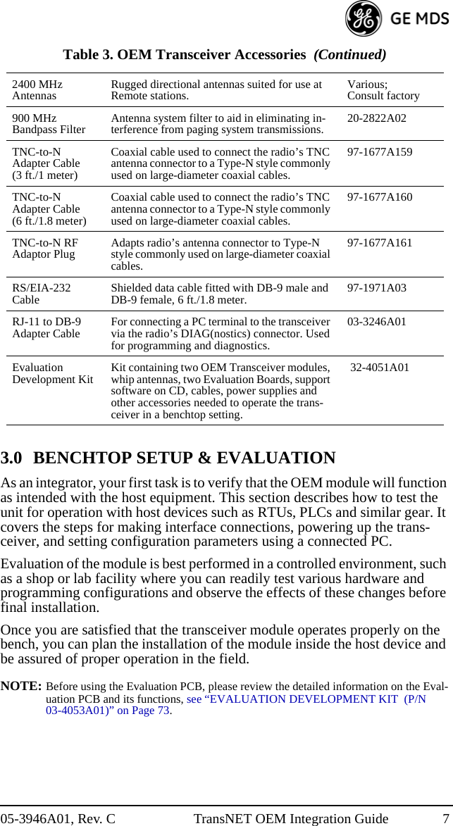
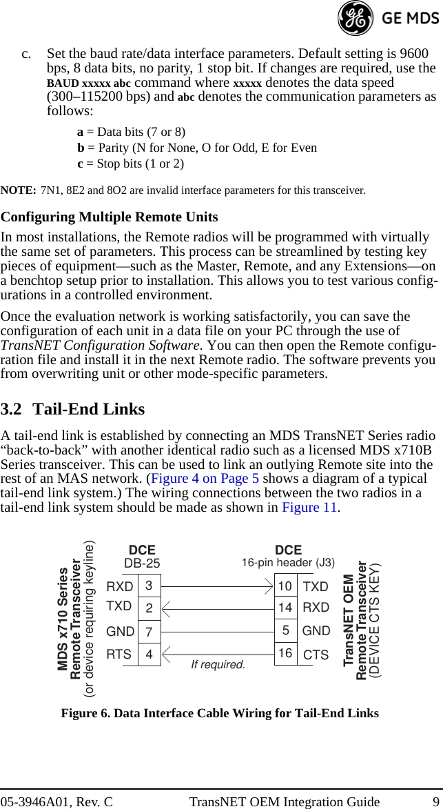
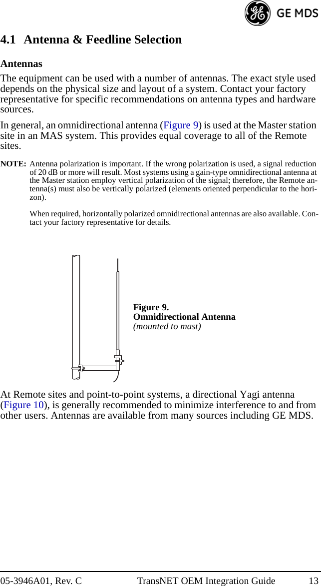
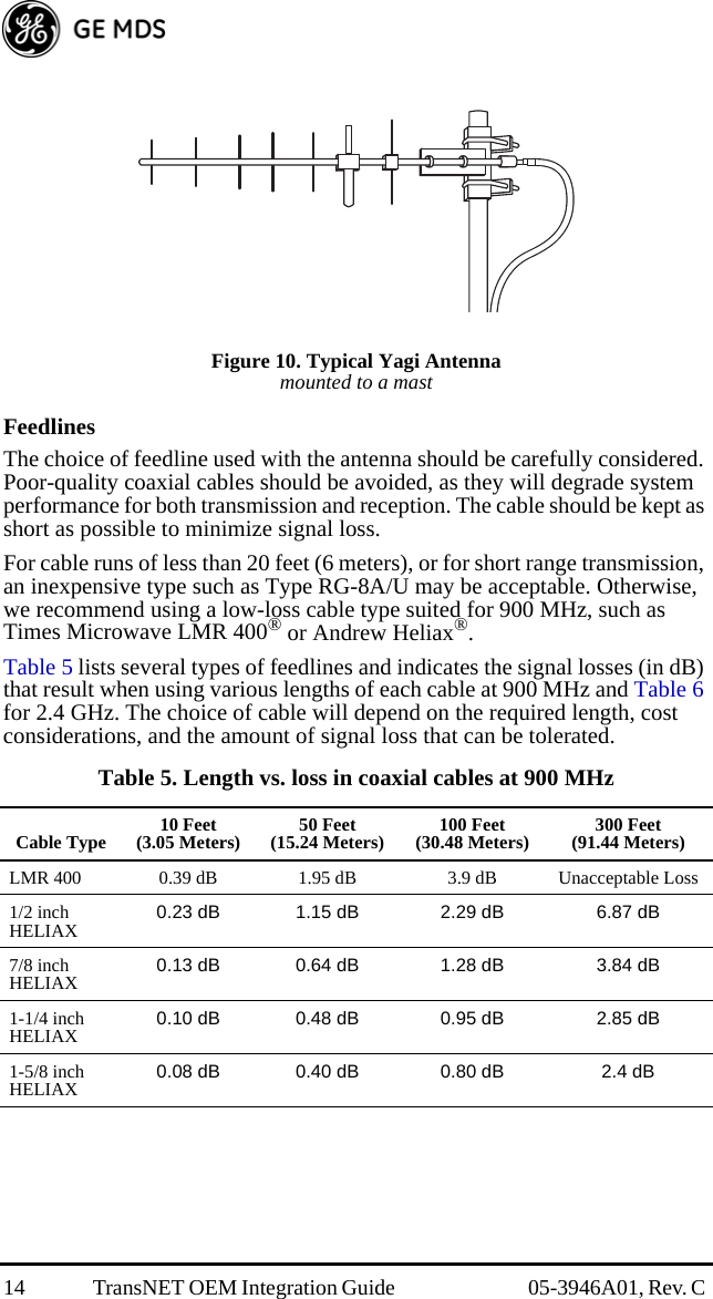
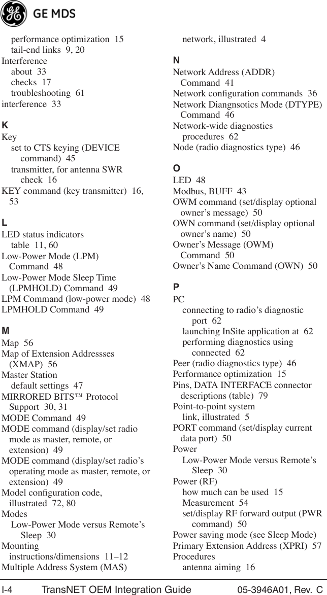
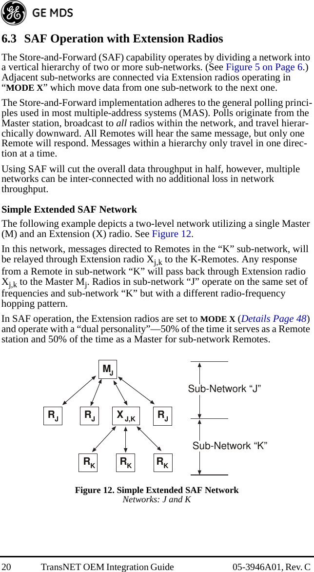
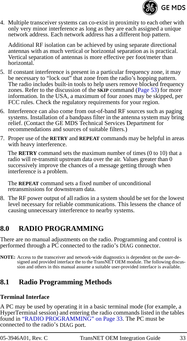
![16 TransNET OEM Integration Guide 05-3946A01, Rev. C Antenna AimingFor optimal performance, directional antennas must be accurately aimed in the direction of desired transmission. The easiest way to do this is to point the antenna in the approximate direction, then use the Remote radio’s RSSI command (Received Signal Strength Indicator) to further refine the heading for maximum received signal strength.In an MAS system, RSSI readings are only meaningful when initiated from a Remote station. This is because the Master station typically receives signals from several Remote sites, and the RSSI would be continually changing as the Master receives from each Remote in turn. Adjust the antenna for the highest (most positive) value to ensure the greatest communication reliability.Antenna SWR CheckIt is necessary to briefly key the transmitter for this check by placing the radio in the SETUP mode (Page 52) and using the KEY command. (To unkey the radio, enter DKEY; to disable the SETUP mode and return the radio to normal operation, enter Q or QUIT.)The SWR of the antenna system should be checked before the radio is put into regular service. For accurate readings, a wattmeter suited for 1000 MHz is required. One unit meeting this criteria is the Bird Model 43 directional watt-meter with a 5J element installed.The reflected power should be less than 10% of the forward power (2:1 SWR). Higher readings usually indicate problems with the antenna, feedline or coaxial connectors.Data Buffer Setting—MODBUS™ ProtocolThe default setting for the data buffer is OFF. This allows the radio to operate with the lowest possible latency and improves channel efficiency. MODBUS™ protocol and its derivatives are the only protocols that should require the buffer to be turned on. See “BUFF [ON, OFF]” on Page 42 for details.NOTE: The BUFF ON setting may introduce high latency. For time-critical MODBUSTM ap-plications, buffering can also be achieved by setting the RXD delay value. This lowers the latency, but may not be as robust as BUFF ON. The desired RXD value can be ap-proximated by the following:RXD value = (9600/BAUD value) * HOPTIME value * REPEAT value * SAF multi-plier. (The SAF multiplier is 1 for SAF OFF and 2 for SAF ON.)As an example, with 9600bps, HOPTIME 7, REPEAT 3, SAF ON, the RXD delay should typically be set to 42. ([9600/9600] * 7 * 3 * 2 = 42)Hoptime SettingThe default hop-time setting is 7 (7 ms). An alternate setting of 28 millisec-onds may be used to increase throughput, but at the cost of increased latency. More information on the HOPTIME command can be found on Page 45.](https://usermanual.wiki/GE-MDS/DS-EL806.User-Manual/User-Guide-1465711-Page-28.png)
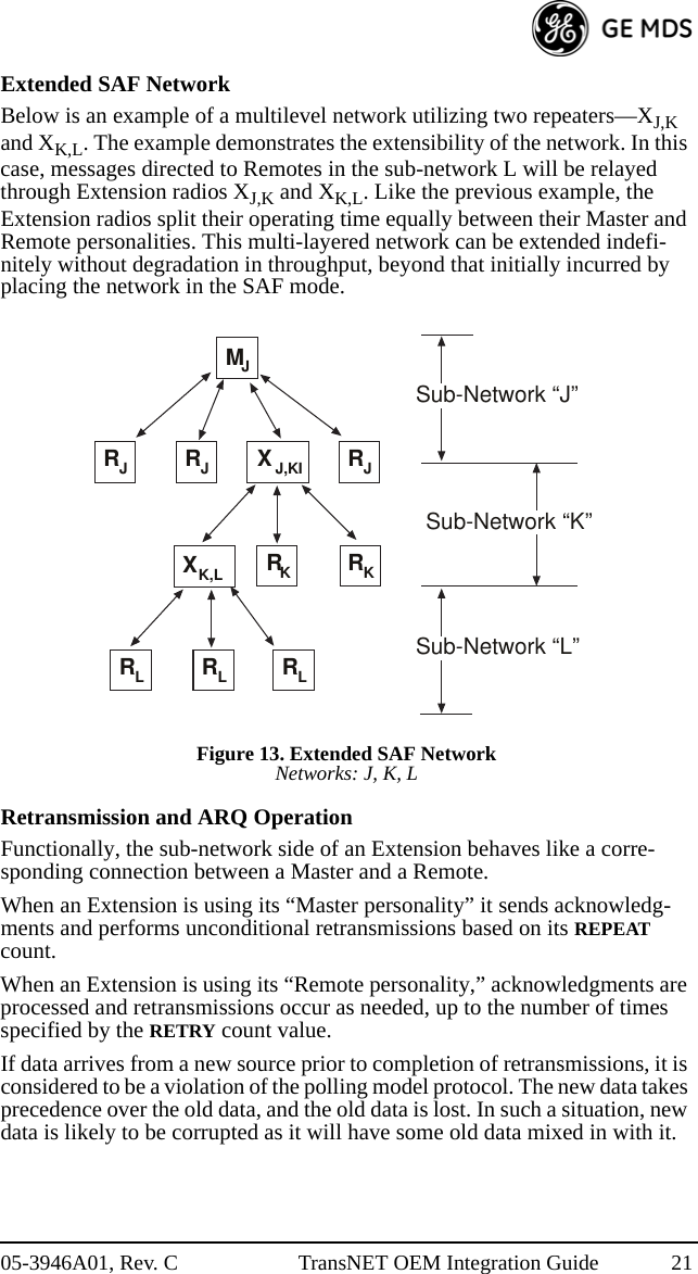
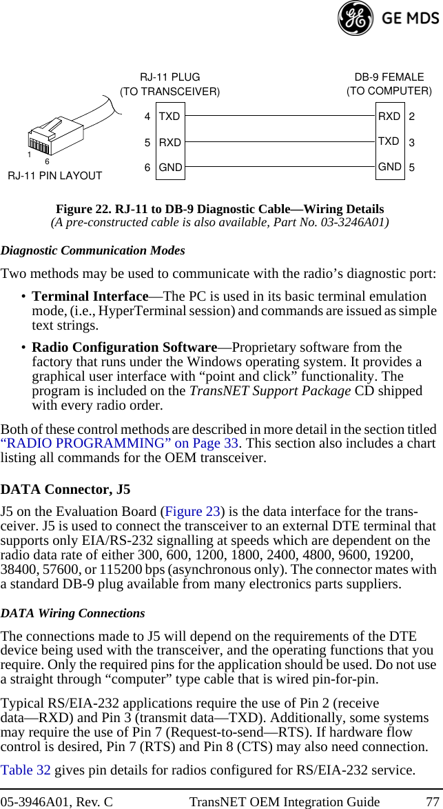
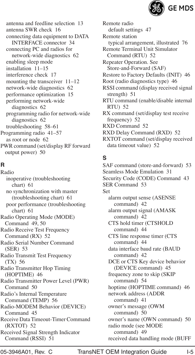
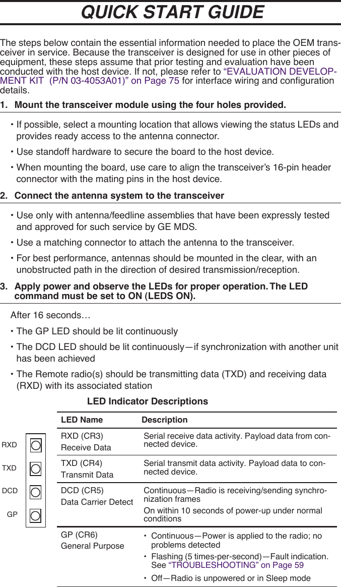
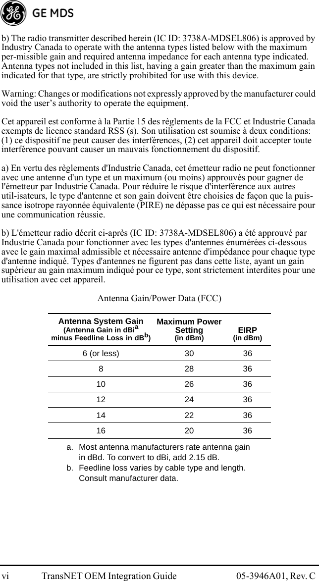
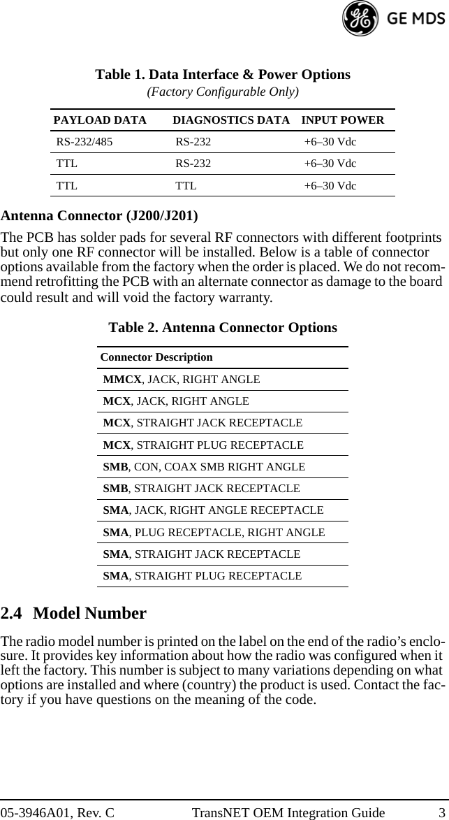
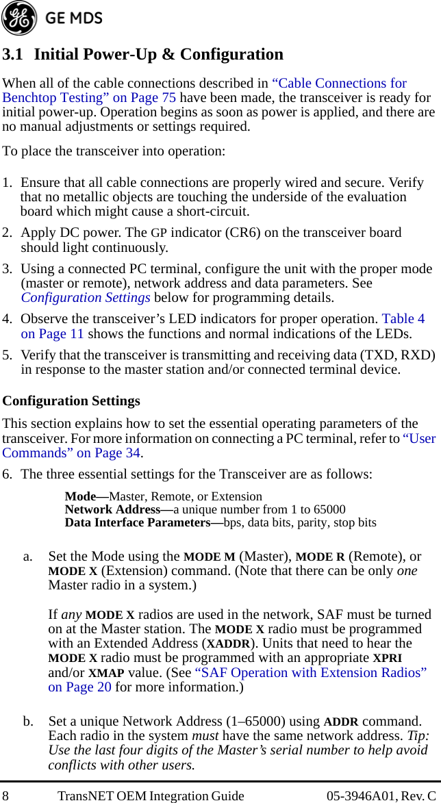
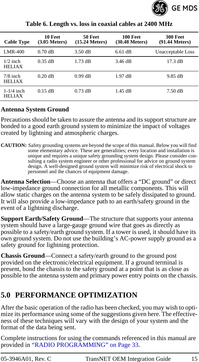
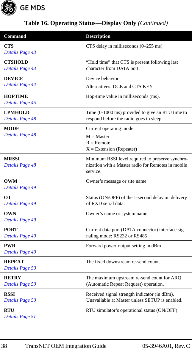
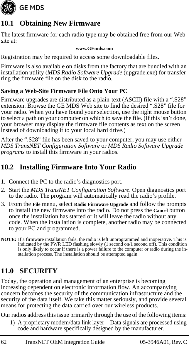
![22 TransNET OEM Integration Guide 05-3946A01, Rev. C SAF Configuration ExampleThe following is an outline for the configuration of a simple store-and-forward link.1. Mode X and M Radios—Can have direct reports (Mode R radios) out-side of the chain.2. Data (Payload)—Travels from Master to Remote, and back from Remote to Master.3. Mode X and R Radios—Extension links can be protected by mapping one or more fall-back paths in case of a failure. Add secondary exten-sion addresses (XADDR) into the XMAP table. (See “XMAP [00000000-FFFFFFFF]” on Page 55.) For example, as shown in Figure 14, Remote “D” could use Remote “C” as its extension primary, and Remote “B” (X ADDR = 1) as an alterna-tive in case of a failure of Remote “C” (X ADDR = 2). This arrange-ment assumes a serviceable path between Remotes “D” and “B” and requires Remote “D” to be programmed with XMAP = 2 to correspond with the XADDR address of Remote “B.”Invisible place holderFigure 14. SAF Configuration ExampleThis configuration is easily arranged through the use of the Extension Map in the MDS TransNET Configuration Software’s “Store-and-Forward Settings.”6.4 Using AT Commands A TransNET network may be configured to support protocols employing Hayes-Compatible modem commands through the radio’s AT Mode. In this mode, TransNET units can provide a communications replacement for dial-up modems where the RTUs and the protocol do not contain address-ability, and the establishment of a direct-communications link is the only way to determine if the RTU has data ready to be sent. This requirement is common in many older SCADA systems which were developed for direct connections where wire lines were the only communica-tions link available at the time. Most of these older system implemented support for the AT commands needed in the host software, so TransNET units can be used without software modifications.A B C D EMODE = MADDR = 1234X ADDR = ØX PRI = NoneMODE = XADDR = 1234X ADDR = 1X PRI = ØMODE = XADDR = 1234X ADDR = 2X PRI = 1MODE = XADDR = 1234X ADDR = 3X PRI = 2XMAP = 2MODE = RADDR = 1234X ADDR = 4X PRI = 3TransNETRadios:RadioConfguration:](https://usermanual.wiki/GE-MDS/DS-EL806.User-Manual/User-Guide-1465711-Page-34.png)
![05-3946A01, Rev. C TransNET OEM Integration Guide 23In this mode, the Master’s DATA port is parsed for a subset of AT commands. (See Supported Commands below). When an ATDTxxxxx data sequence is detected, and xxxxx is a unit address of a radio in the network, the TransNET Master will establish a virtual link to that unit. It will remain in that state until either another ATDTxxxxx or ATH (hang-up/disconnect) is detected. (Note: Unaddressed Remotes in the network will not respond to user data. Data will only be exchanged between the equipment connected to the addressed Remote unit and the network or device connected to the Master’s DATA port.To use this mode, the command AT ON must be selected at the Master Radio. The acknowledgment to an ATDT command is simulated by the Master; there is no true verification that the far-end connection is valid.Please consider the following additional information before using the AT commands:• Radio commands and AT commands are independent with unique syntax and functional objectives.•ATDT is not a radio command; it is part of the payload data input and follows the syntax for Hayes-compatible landline modems.• TransNET commands are entered through the RJ11 DIAGNOSTIC port on Master and Remote radios. AT ON and UNIT are examples of TransNET commands.• AT commands are only entered through the Master’s DATA port, and only when the TransNET command AT ON has been previously issued. The radio supports a subset of the Hayes-compatible modem AT set. Each command is entered without spaces, and always begins with AT, and ends with a carriage return key press.Supported AT CommandsSupported modem commands on the payload port are:AT <attention>Replies with OK (Code 0).ATDT[xxxxx] <dial>The command xxxxx represents 5-digit unit address with a leading zero (0) if applicable. This command replies with CONNECT (Code 1). Once connected, all characters are passed through until a +++ is seen.ATH <hang up> or +++This command replies with OK (Code 0) and deletes any virtual connection to the currently addressed Remote station.ATV[x] <change verbosity>x = 0, means use numeric messagesx = 1, means use text messages (Default)Replies with OK (Code 0)AT <command errors>Replies with ERROR (Code 4)Characters with <no AT command>](https://usermanual.wiki/GE-MDS/DS-EL806.User-Manual/User-Guide-1465711-Page-35.png)
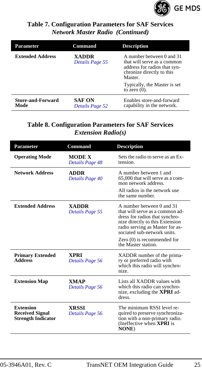
![24 TransNET OEM Integration Guide 05-3946A01, Rev. C Modem will echo characters in the data stream but will be ignored until a second “AT” is seen at which time the modem closes the virtual connection.Operating Notes when AT Commands are ON• Radios will not poll with the embedded RTU simulator unless a connection is established.• Network-wide diagnostics are unaffected by the dialed unit connection status.• The use of the TransNET OT command (Output Trigger) can be of benefit in some configurations. See “OT [ON, OFF]” on Page 49 for configuration details.6.5 Configuration Parameters for Store & Forward ServicesThe installation and configuration of a radio network with an Extension using SAF is straightforward with only a few unique parameters that need to be considered and set at each unit.In every network there can be only one Master station. It will serve as the sole gateway to the outside world. The following three tables detail the parameters that will need to be set on each type of radio in the network. • Network Master Radio—Table 7 on Page 24• Extension Radio(s)—Table 8 on Page 25• Remote Radio(s)—Table 9 on Page 26 Table 7. Configuration Parameters for SAF ServicesNetwork Master Radio Parameter Command DescriptionOperating Mode MODE MDetails Page 48 Sets the radio to serve as a Master.Network Address ADDRDetails Page 40 A number between 1 and 65,000 that will serve as a common network address.All radios in the network use the same number.](https://usermanual.wiki/GE-MDS/DS-EL806.User-Manual/User-Guide-1465711-Page-36.png)
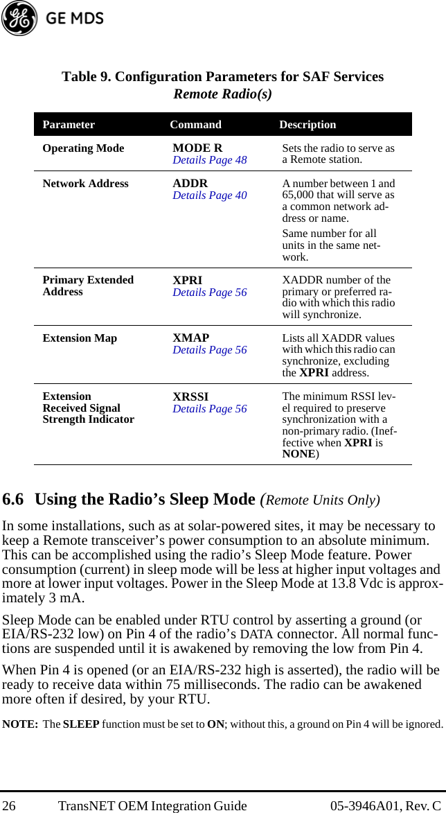
![05-3946A01, Rev. C TransNET OEM Integration Guide 27It is important to note that power consumption will increase somewhat as communication from the Master station degrades. This is because the radio will spend a greater period of time “awake” looking for synchronization messages from the Master radio.In order for the radio to be controlled by Pin 4, the unit’s Sleep Mode must be enabled through the SLEEP [ON, OFF] command. See “SLEEP [ON, OFF]” on Page 54 for more information.NOTE: If INTRUSIVE polling is used in InSite NMS software, it is necessary to select SLEEP MODE INHIBIT ON from the Polling Options menu, on the Network Wide Diag-nostic Polling screen.Sleep Mode ExampleThe following example describes Sleep Mode implementation in a typical system. Using this information, you should be able to configure a system that meets your own particular needs.Suppose you need communications to each Remote site only once per hour. Program the RTU to raise an EIA/RS-232 line once each hour (DTR for example) and wait for a poll and response before lowering it again. Connect this line to Pin 4 of the radio’s DATA connector. This will allow each RTU to be polled once per hour, with a dramatic reduction in power consumption.6.7 Low-Power Mode (LPM)—Master EnabledThe Low-Power Mode (LPM) puts Remote radios into a configuration similar to Sleep, but with some important distinctions. The most important difference is that the radio will automatically go to sleep in this mode, regardless of the condition of Pin 4 of the DATA interface connector.This feature trades increased latency to gain power savings. The low-power mode (LPM) automatically saves power at a Remote by instructing the Remote to shutdown for long periods of time between SYNC messages. Master transmissions are automatically blocked while the Remotes are asleep. Note, both Masters and Remotes are adaptive and will suppress a normal sleep interval until after the end of a current data transmission or reception.Setup CommandsThese are the command options and their applications:•LPM 1 at the Master enables low-power mode network-wide; all Remotes pick it up and start saving power by automatically sleeping.LPM 1 can work in conjunction with the AT dialing feature. The dialed unit will be forced awake; all others will sleep.•LPM 0 at the Master is used to disable low-power mode (LPM)(Default setting following an INIT or firmware upgrade.)For LPMHOLD 0 with REPEAT 0 setting, a Remote with no data to send will consume about 1/4 of its normal power consumption. Note that the SLEEP command must be enabled for the LPM to function.](https://usermanual.wiki/GE-MDS/DS-EL806.User-Manual/User-Guide-1465711-Page-39.png)
![28 TransNET OEM Integration Guide 05-3946A01, Rev. C Reading RSSI & Other Parameters with LPM EnabledIt may be desired to perform tests and review operational settings of a Remote radio which has been programmed to operate in the low-power mode. Follow the abbreviated procedure below to interact with the radio through a local computer.• Disconnect the Remote’s antenna to force it to lose sync with the Master• Power-down the radio• Connect a computer running TransNET configuration software to the Remote’s DIAG(nostic) port.• Power-up the radio• Reconnect the antenna• Measure the RSSI or review and change any parameters you desirePower Consumption Influence by HOPTIME and SAF SettingsTable 10 shows representative current consumption and data delay values for various settings of TransNET radios setup for Low Power Mode, LPM (See “LPM [1, 0]” on Page 47). It assumes the primary power voltage is 13.8 Vdc and the polling rate is minimized to yield best-case power consumption (current) values.The more each RTU is polled and asked to transmit, the more current will be consumed. Therefore, these values are the lowest that can be expected. Power consumption (current) is inversely related to data delay as shown in the table. When a radio is sleeping (LPM) mode, it is also waiting longer to deliver the payload data.Note, the Store-and-Forward setting has a significant effect on power consumption, as it effectively doubles the HOPTIME to support LPM services. For the most power-efficient operation, turn on SAF even if you are not using repeaters.Table 10. Power Consumption versus Hoptime and SAF SettingsHOPTIME SAF Current (ma) Data Delay7 OFF 16 350 ms7 ON 10 780 ms28 OFF 7 1620 ms28 ON 4 3360 ms](https://usermanual.wiki/GE-MDS/DS-EL806.User-Manual/User-Guide-1465711-Page-40.png)
![34 TransNET OEM Integration Guide 05-3946A01, Rev. C Once connected, communication (baud rate) is established through the command interface. To access the command interface, press the key, followed by one or more keystrokes (delivered at about half-second intervals), until the “>” prompt is displayed.NOTE: The DIAG port (RJ-11 connector) uses 8 data bits, 1 stop bit, and no parity. It can au-tomatically configure itself to function at 1200, 2400, 4800, 9600, 19200, 38400, 57600, and 115200 bps. [Default: BAUD = 9600]If the DLINK setting is ON, the DIAG port will start out in Diagnostic Link mode. This is a special protocol used to support Network-Wide Diagnostics. The process described in the paragraph above causes the radio to exit the diagnostic link mode and enter the command mode. If there is no input in command mode for 5 minutes, the DIAG port will revert back to diagnostic link mode.PC-Based Configuration ToolThe MS Windows™-based MDS TransNET Configuration Software (P/N 06-4059A01) is designed for use with a PC connected to the radio’s diagnostics port.The TransNET Configuration Software provides access to all of the radio’s capabilities with the benefit of context-sensitive help. The program is shipped as part of the TransNET support CD included with every order (Part No. 03-2708A02)8.2 User CommandsA series of tables begin on the next page that provide reference charts of various user commands for the transceiver. See “Detailed Command Descrip-tions” on Page 40 for more details.Entering CommandsThe proper procedure for entering commands is to type the command, followed by an keystroke. For programming commands, the command is followed by , the appropriate information or values, and then .ESCENTERENTERSPACEENTER](https://usermanual.wiki/GE-MDS/DS-EL806.User-Manual/User-Guide-1465711-Page-46.png)
![05-3946A01, Rev. C TransNET OEM Integration Guide 35 Table 13. Network Configuration—Master Station COMMAND DESCRIPTION AT [ON, OFF] Details Page 41 Enables Master station to emulate a modem and respond to AT commandsBUFF [ON, OFF] Details Page 42 ON = Seamless dataOFF = Fast byte throughput.FEC [ON, OFF] Details Page 45 Sets/disables FEC (Forward Error Correction) setting.HOPTIME [7, 28]Details Page 45 Displays hop-time or sets it to 7 or 28 ms.LPM [1, 0]Details Page 47 Used at Master to set all associated stations in an energy-conservation mode.1 = Low-power mode enabled network-wide0 = Disable low-power mode (Default)REPEATDetails Page 50 Sets/displays the fixed downstream re-send count.RETRY [0–10]Details Page 50 Sets/displays the maximum upstream re-send count for ARQ (Automatic Repeat Request) opera-tionSAF [ON, OFF]Details, page 52 Enables/disables the store-and-forward function for the network controlled by this Master unit.SKIP [NONE, 1...8]Details, page 53 Skip one or more frequency zonesTable 14. Network-Wide Diagnostics Command DescriptionDLINK [xxxxx/ON/OFF]Details, page 44 Controls operation of diagnostic link function.DTYPE [NODE/ROOT]Details, page 45 Set radio’s operational characteristics for network-wide diagnostics](https://usermanual.wiki/GE-MDS/DS-EL806.User-Manual/User-Guide-1465711-Page-47.png)
![36 TransNET OEM Integration Guide 05-3946A01, Rev. C Table 15. Operational Configuration—Set/Program Command DescriptionADDR [1–65000]Details, page 40 Program network addressAMASK [0000 0000–FFFF FFFF]Details, page 41 Alarm responseDefault: FFFF FFFFASENSE [HI/LO]Details, page 41 Sense of the alarm output on Pin 6 of the INTER-FACE connector in the EIA-232 mode. Default: Alarm present = HIBAND [A, B, C] Details Page 42 Selects one of three operating bands.(2.4 GHz Model Only)BAUD [xxxxx abc]Details, page 41 Data communication parametersCODE [NONE, 1…255]Details, page 42 Select the security/encryption setting in the radioCSADDR [1–65000, NONE]Details, page 43 Used on a single Master/Remote network to sup-port TDD-style simulated full-duplex.CTS [0–255]Details, page 43 CTS delay in milliseconds(A value of 0 returns CTS immediately)CTSHOLD [0–60000]Details, page 43 “Hold time” that CTS is present following last character from DATA port.DEVICE [DCE, CTS KEY]Details, page 44 Device behavior: DCE (normal) or CTS KeyMODE [M, R, X]Details, page 48 Operating mode: M = Master, R = Remote, X = ExtensionMRSSI [NONE, –40...–90]Details, page 48 Minimum RSSI level required to preserve syn-chronization with a Master radio for Remotes in mobile service.OT [ON, OFF]Details, page 49 Enables a 1-second delay on delivery of RXD serial data.OWN [xxxxx]Details, page 49 Owner’s name, or alternate message(30 characters maximum)PORT [RS232, RS485]Details, page 49 Data port (DATA connector) interface signaling mode: RS232 or RS485PWR [20–30]Details, page 49 Power output in dBm (Figure 35 on Page 84)RXD [0–255]Details, page 51 Set RXD delay time for virtual seamless mode with low latency](https://usermanual.wiki/GE-MDS/DS-EL806.User-Manual/User-Guide-1465711-Page-48.png)
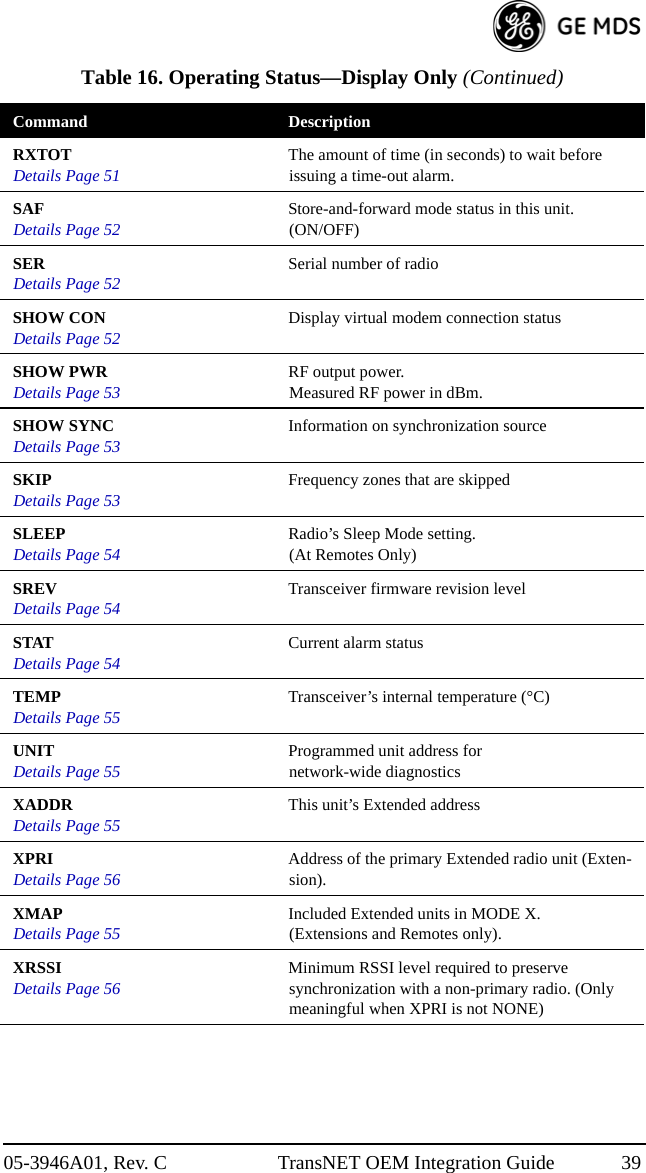
![05-3946A01, Rev. C TransNET OEM Integration Guide 37 RXTOT [NONE, 0–1440]Details, page 51 Maximum duration (in minutes) before time-out alarm. Default is OFF.RTU [ON, OFF, 0-80]Details, page 51 Enable or Disable unit’s built-in RTU simulator. Default is OFF. Set RTU address between zero and 80.SLEEP [ON, OFF]Details, page 54 Enable or Disable the radio’s energy-conservation Sleep mode function.UNIT [10000–65000]Details, page 55 Unit address used for network-wide diagnostics. (Unique within associated network.)XADDR [0–31]Details, page 55 This unit’s Extended addressTypically, the Master is set to zero (0).XMAP [00000000-FFFFFFFF]Details, page 55 Included Extended units in MODE X. (Extensions and Remotes only) XPRI [0–31]Details, page 56 Address of the primary Extended radio unit (Extension).XRSSI [NONE, –40...–120]Details, page 56 Minimum RSSI level required to preserve syn-chronization with a non-primary radio. (Only meaningful when XPRI is not NONE)ZONE CLEARDetails, page 56 Reset zone data statisticsTable 16. Operating Status—Display Only Command DescriptionADDRDetails Page 40 Network addressAMASKDetails Page 41 Alarm mask (response)ASENSEDetails Page 41 Current sense of the alarm output.BAUDDetails Page 41 Data communication parameters. Example: BAUD 9600 8N1BUFFDetails Page 42 Data buffering mode: ON = seamless data, OFF = fast byte throughputCODEDetails Page 42 Security/encryption operational status.“NONE” (Inactive), or “ACTIVE”Table 15. Operational Configuration—Set/Program (Continued)Command Description](https://usermanual.wiki/GE-MDS/DS-EL806.User-Manual/User-Guide-1465711-Page-49.png)
![40 TransNET OEM Integration Guide 05-3946A01, Rev. C 8.3 Detailed Command DescriptionsThe essential commands for most applications are Network Address (ADDR), Mode (MODE), and Baud Rate (BAUD). However, proper use of the additional commands allows you to tailor the transceiver for a specific use, or to conduct basic diagnostics on the radio. This section gives more detailed information for the commands listed above in Section 8.2.Most of the commands below can be used in two ways. First, you can type only the command name (for example, ADDR) to view the currently programmed data. Second, you can set or change the existing data by typing the command, followed by a space, and then the desired entry (for example, ADDR 1234). In the descriptions which follow, allowable programming vari-ables, if any, are shown in brackets [ ] following the command name.ADDR [1–65000]Network AddressThis command sets or displays the radio’s network address. The network address can range from 1 to 65000.A network address must be programmed at the time of installation and must be common across each radio in a given network. Radios are typically shipped with the network address unprogrammed, causing the address to display as NONE. If the address is not set (or is set to a wrong value) it leaves the system in an invalid state, preventing operation and generating an alarm.NOTE: It is recommended that the last four digits of the Master radio’s serial number be used for the network address. This helps avoid conflicts with other users.Table 17. Diagnostic and Test Functions Command DescriptionKEYDetails Page 47 Enables the transmitter test. (Must be in Setup mode. Details on page 52.)DKEYDetails Page 44 Turns off the transmitter test. (Must be in Setup mode. Details on page 52.)TX [xxxx]Details Page 55 Set/display transmit test frequency. (Must be in Setup mode. Details on page 52.)RX [xxxx]Details Page 51 Set/display receive test frequency. (Must be in Setup mode. Details on page 52.)SETUPDetails Page 52 Enables Setup mode. Times out after 10 minutes. Press “Q” to quit.ZONE DATADetails Page 56 Zone data statisticsZONE CLEARDetails Page 56 Clears the Zone Data log](https://usermanual.wiki/GE-MDS/DS-EL806.User-Manual/User-Guide-1465711-Page-52.png)
![05-3946A01, Rev. C TransNET OEM Integration Guide 41AMASK [0000 0000–FFFF FFFF]Alarm MaskThis command sets the alarm bits that cause the alarm output signal to be trig-gered. The PWR LED still flashes for all alarms, but the alarm output signal is only activated for those alarms having the corresponding mask bit set. The hex value for the mask aligns directly with the hex value for the ALARM command. The default is FFFF FFFF. Through proper use of the AMASK command, it is possible to tailor the alarm response of the radio. Contact the factory for more information on configuring the alarm mask.AT [ON, OFF]Hayes-Compatible AT Command SupportAT-style modem commands, also know as “Hayes-Compatible Commands”, can be processed through the payload port. By setting AT ON at the Master (MODE M), individual Remotes can be accessed by using ATDT [Unit Address]. In this mode, RTUs designed only for dial-up access can be accessed through the Master station. For more details, see See “Using AT Commands” on Page 22 and “OT [ON, OFF]” on Page 49.ASENSE [HI/LO]Alarm Output SenseThis command is used to set the sense of the alarm output at Pin 3 of the OEM module’s INTERFACE connector, J3, and Pin 6 of the Evaluation’ PCB’s DATA connector. The default is HI which means an alarm is present when an RS-232 high is on Pin 6.BAUD [xxxxx abc]Data Interface Port Baud RateThis command sets or displays the communication attributes for the normal payload communications through the DATA port. The command has no effect on the RJ-11 DIAG(NOSTICS) port.The first parameter (xxxxx) is baud rate. Baud rate is specified in bits-per-second and must be one of the following speeds: 300, 600, 1200, 1800, 2400, 4800, 9600, 19200, 38400, 57600, or 115200. At baud rates of 19200 bps or less, the radio supports unlimited continuous data transmission at any hop rate.The second parameter of the BAUD command (abc) is a 3-character block indicating how the data is encoded. The following is a breakdown of each character’s meaning:a = Data bits (7 or 8)b = Parity (N for None, O for Odd, E for Even)c = Stop bits (1 or 2)The factory default setting is 9600 baud, 8 data bits, no parity, 1 stop bit (Example: 9600 8N1).NOTE: 7N1, 8O2, and 8E2 are invalid communication settings and are not supported by the transceiver.](https://usermanual.wiki/GE-MDS/DS-EL806.User-Manual/User-Guide-1465711-Page-53.png)
![42 TransNET OEM Integration Guide 05-3946A01, Rev. C BAND [A, B, C]Select Sub-Band (Normally used for 2.4 GHz model)This command sets or displays the receiving and transmit operating band for the radio.A = 2.4016–2.4270 GHzB = 2.4272–2.4526 GHzC = 2.4528–2.478.2 GHzNOTE: The same BAND setting must be common across each radio in a given network and it must be programmed at the time of installation. BUFF [ON, OFF]Data Buffer ModeThis command sets or displays the received data handling mode of the radio. The command parameter is either ON or OFF. (The default is OFF.) The setting of this parameter affects the timing of received data sent out the DATA connector. Data transmitted over the air is unaffected by the BUFF setting.If data buffering is set to OFF, the radio will operate with the lowest possible average latency. Data bytes are sent out the DATA port as soon as an incoming RF data frame is processed. Average and typical latency will both be below 10 ms, but idle character gaps may be introduced into the outgoing data flow.If data buffering is ON, the radio will operate in a seamless mode. That is, data bytes will be sent over the air as quickly as possible, but the receiver will buffer the data until the entire packet has been collected. The delay introduced by data buffering is variable and depends on message size and the number of retransmissions required, but the radio will not create any gaps in the output data stream. This mode of operation is required for protocols such as MODBUS™ that do not allow gaps in their data transmission.Seamless mode (BUFF ON) is intended only for applications where the message size is 256 characters or less. Enforcement of this rule is left up to the user. If more than 256 characters are transmitted data delivery will not be seamless and data may be lost.Changes to the BUFF setting may only be made at the Master radio, as the Master radio broadcasts the buffer setting for the entire network. At Remote radios, the buffer setting may be read when the radio is in synchronization with the Master, but it cannot be changed.CODE [NONE, 1…255]Security CodeThe CODE command is used to select or display the security/encryption setting in the radio.The default is CODE NONE. Setting CODE to a value other than NONE provides an extra level of security beyond that provided by the Network Address (ADDR). The disadvantage is increased complexity in managing the network.](https://usermanual.wiki/GE-MDS/DS-EL806.User-Manual/User-Guide-1465711-Page-54.png)
![05-3946A01, Rev. C TransNET OEM Integration Guide 43The CODE command takes an argument of 1…255, or NONE. Entering CODE without an argument will display either NONE or ACTIVE. ACTIVE means that security/encryption has been enabled, but the radio will not display the security argument.When a CODE value is active, all radios in the system must use the same code value. If the code value is not properly programmed, a Remote radio will not synchronize with the Master.CAUTION: Record the CODE value and store it in a safe place. If the code is later forgotten, and a unit is to be added to the system, all radios in the network must be set to NONE and then reprogrammed to a new value.CSADDR [1–65000, NONE]Clock-Synchronizing Master AddressUsed to specify the network address of a “Clock-Sync” Master station to which this station will be synchronized. Also see “ADDR [1–65000]” on Page 40 and “Co-Located and Close-Proximity Masters” on Page 30 for further details.CTS [0–255]Clear-to-Send DelayThe CTS (clear-to-send) command sets or displays the timer value associated with the CTS line response. The command parameter ranges from 0 to 255 milliseconds.For DCE operation, the timer specifies how long to wait after the RTS line goes high before asserting the CTS line. A timer value of zero means that the CTS line will be asserted immediately following the assertion of RTS.For CTS Key operation (see the DEVICE command), the timer specifies how long to wait after asserting the CTS line before sending data out the DATA port. A timer value of zero means that data will be sent out the data port without imposing a key-up delay. (Other delays may be in effect from other radio operating parameters.)CTSHOLD [0–60000]Clear-to-Send Hold TimeUsed in DEVICE CTS KEY mode, this command sets the amount of time in milliseconds that CTS remains present following transmission of the last character out the RXD pin of the DATA port. This “hold time” can be used to prevent squelch tail data corruption when communicating with other radios.The CTSHOLD setting can range from 0 to 60000 (i.e., 60 seconds). The default value is 0, which means that CTS will drop immediately after the last character is transmitted. If the command is entered when the radio is in DEVICE DCE mode, the response CTSHOLD N/A will be displayed.](https://usermanual.wiki/GE-MDS/DS-EL806.User-Manual/User-Guide-1465711-Page-55.png)
![44 TransNET OEM Integration Guide 05-3946A01, Rev. C DEVICE [DCE, CTS KEY]Radio-MODEM BehaviorThe DEVICE command sets or displays the device behavior of the radio. The command parameter is either DCE or CTS KEY.The default selection is DCE. In this mode, CTS will go high following RTS, subject to the CTS programmable delay time. Keying is stimulated by the input of characters at the data port. Hardware flow control is implemented by dropping the CTS line if data arrives faster than it can be transmitted.If CTS KEY is selected, the radio is assumed to be controlling another radio, such as in a repeater or tail-end link system. The RTS line is ignored and the CTS line is used as a keyline control for the other radio. CTS is asserted immediately after the receipt of RF data, but data will not be sent out the DATA port until after the CTS programmable delay time has expired. (This gives the other radio time to key.)Following transmission of the last byte of data, CTS will remain asserted for the duration specified by the CTSHOLD command. CTSHOLD should be set sufficiently high.DLINK [xxxxx/ON/OFF]InSite Diagnostics Link SupportDLINK ON enables use of Diagnostic Link mode and establishes it as the default protocol on the DIAG port. Diagnostic Link mode is a special protocol used to support Network-Wide Diagnostics. DLINK must be set to ON to support connection to InSite or to support chained diagnostics between radio networks even while the radio is in sleep mode. DLINK OFF disables this feature. The default setting is ON.The following DLINK baud rates selections are supported:• 1200 • 4800 • 9600 • 19200 (default)• 38400 • 57600 • 115200Example: DLINK 4800 sets the DIAG port to operate at 4800 bps when diag-nostics is closed. This setting will not affect the port’s autobaud operation. Use only of DLINK ON, will enable the use 19200 or the most recently programmed value. The default is DLINK 19200 and DLINK ON. NOTE 1: The same baud rate must be entered into the InSite Equipment List’s BAUD field.NOTE 2: The DLINK rate must match the rate of any connected device to the diagnostic port. This may be either another MDS radio’s diagnostic port, InSite computer, or another data link device that eventually connects to the InSite computer.DKEYTurn Off Radio Transmitter ‘s Test SignalDisables the transmitter when it is keyed. See also KEY command.](https://usermanual.wiki/GE-MDS/DS-EL806.User-Manual/User-Guide-1465711-Page-56.png)
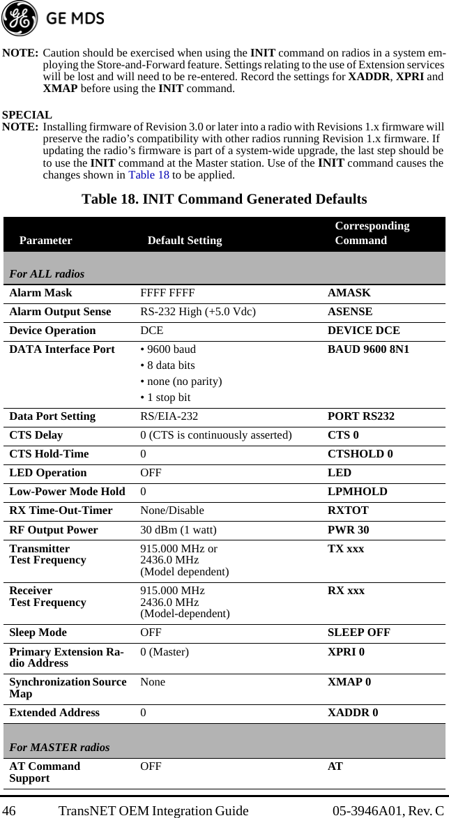
![05-3946A01, Rev. C TransNET OEM Integration Guide 45DTYPE [NODE/ROOT]Network Diagnostics ModeThe DTYPE command specifies the radio’s operational characteristics for network-wide diagnostics. The transceiver uses the following types:•NODE—The most common setting, and the default. This is the basic system radio device-type. Typically, the radio network is comprised of nodes and one root. Intrusive diagnostics can originate from any node. However, non-intrusive diagnostics can only be conducted from the root node.•ROOT—Always one, and only one, per network (including units associated through Extension units.) The root is the focal point of network-wide diagnostics information. Intrusive diagnostics can originate from any radio, including the root. However, the root is the only radio through which non-intrusive diagnostics can be conducted.FEC [ON, OFF]Forward Error CorrectionThis command is used to view the FEC setting, or turn it on or off. The default setting is FEC ON. (It needs to be turned off when throughputs exceed 57,600 bps.) FEC is set at the Master and is automatically passed on to all Remotes in a network.Setting FEC to ON improves sensitivity at the cost of reduced throughput. Typical SCADA/telemetry applications use low data rates and, as such, the FEC setting is normally transparent to them.HOPTIME [7, 28]Radio Transmitter Hop TimingThe HOPTIME command is used to set or display the hop-time setting. The command is a digit corresponding to the hop-time setting in milliseconds. The default HOPTIME setting is 7. A setting of 28 must be used when throughputs exceed 57,600 bps and is recommended when data transmission sizes exceed 256 bytes.Changes to the HOPTIME setting may only be made at the Master radio. (This is because the Master radio establishes the hop-time setting for the entire network.) At Remote radios, the hop-time setting may be read when the radio is in synchronization with the Master, but it cannot be changed.INITInitialize; Restore to Factory DefaultsThe INIT command is used to reset the radio’s operating parameters to the factory defaults listed in Table 18 on Page 46. This may be helpful when trying to resolve configuration problems that resulted from the entry of one or more improper command settings. If you are unsure of which command setting caused the problem, this command allows you to get back to a known working state.](https://usermanual.wiki/GE-MDS/DS-EL806.User-Manual/User-Guide-1465711-Page-57.png)
![05-3946A01, Rev. C TransNET OEM Integration Guide 47HREVHardware RevisionShows the hardware revision of the radio.KEYTurn On Radio Transmitter Test SignalEnables the transmitter. (Radio must be in Setup mode.) See also DKEY command (DKEYDetails, page 44).LED [ON, OFF]Enable/Disable PCB LEDsLED ON enables/disables the PCB board mounted LEDs seen only with the transceiver’s covers removed. LED is normally OFF, it may be useful to have them on for testing the radio with the covers removed. Note: the external LEDs will be dimmer if the LED function is left ON.The LED command also affects the operation of the LEDs in the “Low-Power Mode” (LPM). When LED is OFF, the radio keeps the PWR and SYNC LEDs extinguished.LPM [1, 0]Low-Power Mode—Masters OnlyThis feature trades increased latency to gain power savings. Low-power mode (LPM) automatically saves power at a Remote by instructing the Remote to shutdown for large periods of time in between SYNC messages. Master transmissions are automatically blocked while the Remotes are asleep. Note, both Masters and Remotes are adaptive and will suppress a normal sleep interval if data transmission or reception is in progress.•LPM 1 at the Master enables low-power mode network-wide; all Remotes pick it up and start saving power by automatically sleeping.LPM 1 can work in conjunction with the AT dialing feature. The dialed unit will be forced awake; all others will sleep.Buffer Mode OFF BUFF OFFForward Error Correction ON FEC ONHop-Time 7 ms HOPTIME 7Low-Power Mode 0 (Off) LPMSkipped Frequencies None (radio will hop across all fre-quencies) SKIP NONERetry Count 10 (max. of 10 repeats for ARQ) RETRY 10Repeat Count 3 (downstream repeats) REPEAT 3Table 18. INIT Command Generated Defaults (Continued)Parameter Default Setting Corresponding Command](https://usermanual.wiki/GE-MDS/DS-EL806.User-Manual/User-Guide-1465711-Page-59.png)
![48 TransNET OEM Integration Guide 05-3946A01, Rev. C •LPM 0 at the Master to disable low-power mode (Default setting).The SLEEP command must be enabled for LPM to function. Further, when you enable LPM, the LEDs on the Remote radio dim even though the LPM function is not properly enabled by turning on SLEEP. For more information, see “Low-Power Mode (LPM)—Master Enabled” on Page 27, and “Low-Power Mode versus Remote’s Sleep Mode” on Page 29.LPMHOLD [0–1000]Low-Power Mode Sleep TimeUsed to give an RTU time (0-1000 ms) to respond before the radio goes to sleep. Value determines how long to suppress auto-sleep following reception of the last character sent out of the RXD serial data port.NOTE: Any values entered will be rounded to the nearest multiple of 4 ms.To verify the exact hold time, enter LPMHOLD, the response will give you the value currently being used.MODE [M, R, X]Radio Operating ModeThe MODE command sets or displays the operating mode of the radio. A Master radio is set by MODE M; a Remote set by MODE R, and an Extension is set by MODE X.All units default to Remotes; other modes must be specifically programmed with the MODE command.If MODE X is used, the MODE X radio should be programmed with an Extended Address (XADDR). Units that need to hear this MODE X radio must be programmed with an appropriate XPRI and/or XMAP value.MRSSI [NONE, –40...–90]Minimum RSSI for Mobile OperationThe MRSSI command sets or displays the minimum RSSI level (dBm) of a Master station’s signal to maintain synchronization. When the Master’s signal falls below this level, the Remote will attempt to resynchronize with the next Master it can hear within the same network—same Network Address (ADDR)—and, meets the MRSSI level. See “Mobile Operation Support” on Page 29 for additional information.OT [ON, OFF]Output TriggerThe “output trigger” feature sets up a 1-second default delay on delivery of RXD serial data, however, a receipt of RTS causes cancellation of timer followed by immediate data delivery.Hierarchy Rules:•if OT = ON, RTS always cancels data delay and outputs immediately](https://usermanual.wiki/GE-MDS/DS-EL806.User-Manual/User-Guide-1465711-Page-60.png)
![05-3946A01, Rev. C TransNET OEM Integration Guide 49•if OT = ON, DEVICE = DCE, and RXD = 0, data delay is 1 second or until RTS•if DEVICE = DCE, and RXD = N, data delay is N ms•if DEVICE = CTS KEY, and CTS = N, data delay is N ms or until RTS•if DEVICE = CTS KEY overrides RXD, RXD overrides OT default.OWM [xxxxx]“Owner’s Message”The OWM command sets or displays an optional owner’s message, such as the system name. The entry can contain up to 30 characters.OWN [xxxxx] “Owner’s Name”The OWN command sets or displays an optional owner’s name, such as the site name. The entry can contain up to 30 characters.PORT [RS232, RS485]Data Interface Signaling StandardSelect or identify the current data INTERFACE connector’s, J3, signaling mode: RS232 or RS485. This is the port though which the payload data will pass. Pin descriptions for EIA-232 and EIA-485 variations begin on “Transceiver Module’s Interface Connector, J3, Detailed Pin Descriptions” on Page 66. This command will not function on transceivers with a TTL signalling inter-face.PWR [20–30]Radio Transmitter Power LevelThis command displays or sets the desired RF power output of the radio. The PWR command parameter is specified in dBm and can be adjusted in 1 dBm steps. The default setting is 30 dBm (1 watt) for the 900 MHz model and 27 dBm (0.5 watt) for the 2400 MHz model. To read the actual (measured) power output of the radio, use the SHOW PWR command.In the USA, maximum allowable power is governed by FCC limits on Effec-tive Isotropic Radiated Power output (EIRP). The EIRP limit of +36 dBm on the 900 and 2400 MHz band, means that any user with a net antenna gain greater than 6 dBi on the 900 MHz band, or 9 dBi on the 2400 MHz band, must decrease the PWR setting accordingly. “How Much Output Power Can be Used?” on Page 17 contains a detailed discussion of this topic.](https://usermanual.wiki/GE-MDS/DS-EL806.User-Manual/User-Guide-1465711-Page-61.png)
![50 TransNET OEM Integration Guide 05-3946A01, Rev. C REPEAT [0–10]Downstream Repeat Transmission CountThe REPEAT command affects “downstream” data. The command causes a Master or Extension to always repeat transmissions for the specified number of times (range is 0 to 10; default selection is 3). Unlike the RETRY command, there is no acknowledgment that a message has been received.Use the REPEAT command without a value to display the current setting.RETRY [0–10]Upstream Repeat Transmission CountThe RETRY command affects upstream data. The command selects, or displays, the maximum number of times (0 to 10) that a Remote radio will re-transmit data. The default setting is 10.This command is associated with ARQ (Automatic Repeat Request) opera-tion of the radio and is intended for use in areas with heavy radio interference.When the RETRY command is issued without parameters, the maximum retransmission count is shown. A value of 0 represents no retries, while values of 1 or greater successively improve the chance of data delivery in spectrally harsh environments (at the expense of possibly increased latency). The RETRY value is only setable at the Master. It is readable by a synchro-nized Remote.RSSIReceived Signal Strength IndicatorThis command displays the radio’s Received Signal Strength Indication in dBm (decibels relative to 1 mW). The output can range from –40 dBm to –120 dBm. Command availability and results depend on the mode of opera-tion (Master or Remote). The closer to 0 dBm, the stronger the signal, thus a reading of –70 dBm is stronger than –80 dBm.For a Remote radio, under normal operation, RSSI is based on the average signal strength of the SYNC message received in each of the eight frequency zones. (RSSI is sampled each time a SYNC message is received.) When using the RSSI reading to align a directional antenna, it is important to make changes slowly so that the RSSI reading will provide meaningful results. It will take several seconds to indicate a change in signal level. The radio stays in RSSI mode until is pressed.For a Master radio, under normal operation, entering the RSSI command causes the response NOT AVAILABLE to be returned. This is because a Master is normally receiving signals from several Remote stations and an RSSI reading would be continually changing. The only exception is when the SETUP command has been asserted. This disables hopping and allows reading a “raw” RSSI signal level in real time from a Master or Remote radio.NOTE 1: RSSI readings will not accurately indicate signals stronger than –40 dBm.NOTE 2: RSSI works for Dependent Masters. Command displays “NOT AVAILABLE” if the Dependent Master is not synchronized.ENTER](https://usermanual.wiki/GE-MDS/DS-EL806.User-Manual/User-Guide-1465711-Page-62.png)
![05-3946A01, Rev. C TransNET OEM Integration Guide 51RTU [ON, OFF, 0-80]Remote Terminal Unit SimulatorThis command re-enables or disables the radio’s internal RTU simulator, which runs with factory-proprietary polling programs (poll.exe and rsim.exe). The internal RTU simulator is available whenever a radio has diag-nostics enabled. This command also sets the RTU address to which the radio will respond.The internal RTU can be used for testing system payload data or pseudo bit error rate (BER) testing. It can be helpful in isolating a problem to either the external RTU or the radio. The default RTU setting is OFF.RX [xxxx]Radio Receive Test FrequencyThis command sets or displays the test receive frequency used in place of hopping when the radio is in SETUP mode. The test receive frequency can be reprogrammed to any value between 902.200 MHz and 927.800 MHz, inclu-sive. The factory default setting is 915.000 MHz.RXD [0–255]RXD DelayUsed to set a delay, in milliseconds, of RXD data to emulate a seamless mode with much lower latency in applications where retries are not required. Use a delay of twice the value of the HOPTIME period (See Page45).RXTOT [NONE, 0–1440]Receive Data Timeout-TimerThis command sets or displays the amount of time (in minutes) to wait for the next received data packet before issuing a receiver time-out alarm. The default setting is NONE.SAF [ON, OFF]Store-and-Forward Services SupportThis command enables/disables the operation of the Store-and-Forward services. It can be set only at the network’s Master station, but will effect all radios in the associated network. The default setting is OFF. See related commands: “XADDR [0–31]” on Page 55, “XPRI [0–31]” on Page 56, and “XMAP [00000000-FFFFFFFF]” on Page 55.SETUPSetup Radio TestThis command sets up the transceiver for checking antenna SWR or trans-mitter power with external measuring equipment. Do not use this mode during normal operation.When the SETUP command is entered, the prompt changes to SETUP>, and:• Hopping is disabled.](https://usermanual.wiki/GE-MDS/DS-EL806.User-Manual/User-Guide-1465711-Page-63.png)
![52 TransNET OEM Integration Guide 05-3946A01, Rev. C • Synthesizer frequencies are reset to the test frequencies specified by the TX and RX commands described earlier.• The radio can be keyed using the KEY command. DKEY is used to unkey the radio. (If the radio is left in a keyed state it is automatically unkeyed after 10 minutes.)• The RSSI is sampled in a raw, continuous fashion regardless of whether the unit is a Master or a Remote.Entering Q or QUIT returns the system to normal operation.A timer keeps the Setup mode from accidentally leaving the system disabled. After 10 minutes the system behaves as if Q or QUIT had been entered, returning the unit to normal operation.NOTE: TransNET uses a automatic level control in normal operation to keep transmit power constant over time. This facility is disabled in Setup mode. To test 1 Watt power output in Setup mode, the user must enter PWR 30 followed by KEY. The power output will only be valid for the first couple of seconds. SERRadio Serial NumberDisplays the serial number of the radio.SHOW CONShow Virtual Connection StatusShows virtual connection status established by the latest ATDT command sequence. (Works only with AT ON. See“AT [ON, OFF]” on Page 41)If no connection is established, it displays NONE.If a connection is active, it will display:<Master unit address> TO <Remote (“dialed”) unit address>.SHOW PWRShow Measured RF Transmit PowerThe SHOW PWR command displays the actual (measured) RF power output in dBm. Unlike the PWR command, this command shows the actual level being measured, not the programmed RF power setting.SHOW SYNCShow Clock-Synchronization Master Network AddressWhen used at a Remote station, this command will display Extended Address and Unit Address of the Master or Extension radio to which the Remote is synchronized. The network depth at the Remote, defined as the number of downstream links from the Master, is displayed in parentheses.SHOW SYNC works for Dependent Masters. A value of zero (0) means the station is a Master synchronized to a Clock-Sync Master. The SHOW SYNC command will display an asterisk (*) after depth value if the radio is operating with co-located Masters.](https://usermanual.wiki/GE-MDS/DS-EL806.User-Manual/User-Guide-1465711-Page-64.png)
![05-3946A01, Rev. C TransNET OEM Integration Guide 53SKIP [NONE, 1...8]Skip Radio Operating ZonesThis command sets or displays which, if any, of the eight zones will be skipped from the radio’s hopping sequence. Skipping zones is one way of dealing with constant interference on one or more frequencies in the radio’s operating band. See “DEALING WITH INTERFERENCE” on Page 32 for more information on dealing with interference.Tables 19, 20, 21 and 22 show the frequency range covered by each zone. The command parameter is either the keyword NONE or an undelimited string of up to four digits where each digit 1...8 represents a corresponding zone to skip. (For zone parameter input, the digits can appear in any order and can be optionally separated by a blank space.) The SKIP command is display-only at Remote radios. (Remotes must be synchronized with the Master radio to display the skip status.)In the USA, a maximum of four zones may be skipped for TransNET 900 and a maximum of three zones may skipped for TransNET 2400. Check the regu-latory requirements for your region. The SKIP function may not be permitted in your country and the radio will not respond to the SKIP command. Table 19. 900 MHz Frequency Skip ZonesZONE 1 ZONE 2 ZONE 3 ZONE 4 ZONE 5 ZONE 6 ZONE 7 ZONE 8902.2to905.2905.4to908.4908.6to911.6911.8to914.8915.0to918.0918.2to921.2921.4to924.4924.6to927.6Table 20. 2400 MHz, Band A, Frequency Skip ZonesZONE 1 ZONE 2 ZONE 3 ZONE 4 ZONE 5 ZONE 6 ZONE 7 ZONE 82401.6to2404.62404.8to2407.82408.0to2411.02411.2to2414.22414.4to2417.2417.6to2420.62420.8to2423.82424.0to2427.0Table 21. 2400 MHz, Band B, Frequency Skip ZonesZONE 1 ZONE 2 ZONE 3 ZONE 4 ZONE 5 ZONE 6 ZONE 7 ZONE 82427.2to2430.22430.4to2433.42433.6to2436.62436.80to2439.82440.0to2443.02443.2to2446.22446.4to2449.42449.6to2452.6Table 22. 2400 MHz, Band C, Frequency Skip ZonesZONE 1 ZONE 2 ZONE 3 ZONE 4 ZONE 5 ZONE 6 ZONE 7 ZONE 82452.8to2455.82456.0to2459.02459.2to2462.22462.4to2465.42465.6to2468.62468.8to2471.82472.0to2475.02475.2to2478.2](https://usermanual.wiki/GE-MDS/DS-EL806.User-Manual/User-Guide-1465711-Page-65.png)
![54 TransNET OEM Integration Guide 05-3946A01, Rev. C SLEEP [ON, OFF]Transceiver Sleep—Remotes OnlyThis command is used to set or display the radio’s Sleep Mode setting. The default setting is SLEEP OFF. When this setting is ON (enabled) the Low-Power, or RTU-forced Sleep Mode, can be used. This function cannot be turned on for a Master or Extension radio unless the unit is in the Low-Power Mode. See “Using the Radio’s Sleep Mode (Remote Units Only)” on Page 26 and “Low-Power Mode versus Remote’s Sleep Mode” on Page 29 for more information.SREVFirmware Revision LevelThis command displays the version of the firmware currently loaded into the transceiver.A display of 06-4040A01, 3.6.1 is an example of the firmware version identi-fier—part number followed by release/version number.STATAlarm StatusThis command is used to check the alarm status of the radio. If no alarms exist, the message NO ALARMS PRESENT is returned.If an alarm does exist, a two-digit alarm code (00–31) is displayed and the event is identified as a “Major” or “Minor” alarm. A brief description of the event is also given.If more than one alarm exists, the word MORE appears, and additional alarms may be viewed by pressing the key. Detailed descriptions of the alarm codes are provided in Table 23 on Page 58.TEMPRadio’s Internal TemperatureThis command displays the internal temperature of the transceiver in degrees Celsius. (Note that the radio is specified to operate in an environment between –30° C and +60° C). This internal reading may be higher than the outside temperature by several degrees.TX [xxxx]Radio Transmit Test FrequencyThis command sets or displays the test transmit frequency used in place of hopping whenever the radio is in Setup mode. The test transmit frequency for the 900 MHz radios can be reprogrammed to any value between 902.200 MHz and 927.800 MHz, inclusive. The factory default setting is 915.000 MHz. For the 2400 MHz radios, the test frequency can be programmed to any frequency between 2400.6 MHz and 2482.0 MHz. The default value is 2436.0 MHz.ENTER](https://usermanual.wiki/GE-MDS/DS-EL806.User-Manual/User-Guide-1465711-Page-66.png)
![05-3946A01, Rev. C TransNET OEM Integration Guide 55UNIT [10000–65000]Unit AddressThis command sets the unit addressing for network-wide diagnostics and AT-Command address. The unit address is factory programmed to the last four digits of the radio’s serial number. If re-programmed in the field, the entry must consist of five digits between 10000 and 65000.XADDR [0–31]Extended AddressUsed to display or program the Extended Address of this radio that will serve as a common address for the sub-network synchronized to this Master or Extension. This value can be listed in the XPRI parameter of associated Extension or Remote radios to allow them to synchronize to this radio. We recommend setting the Master to zero (0). It is easy to remember, and is the default address when the INIT command is used. (Programmed only in Master and Extension radios.)XMAP [00000000-FFFFFFFF]Map of Extension AddressesXMAP is a 32-bit hex entry where the least significant bit represents XADDR 0 and the most significant bit represents XADDR 31. The full 32-bit hex value represents the entire list of extensions with which the radio will be allowed to communicate. (Pertains to Remotes and Extensions only.)This parameter is easily programmed through the MDS TransNET Configu-ration Software’s Store-and-Forward Settings panel.XPRI [0–31]Primary Extended AddressWill display or program the extended address of the primary radio with which this radio will attempt to synchronize and communicate. A setting of NONE allows the unit to synchronize with any Master or Extension in the XMAP list. (Parameter only meaningful for Remote or Extension units.)XRSSI [NONE, –40...–120]Extension RSSI LevelThe XRSSI command is used to set the RSSI minimum signal level required to preserve synchronization with a non-primary Extension radio. This param-eter will be ignored if XPRI is set to NONE.ZONE CLEARClear Zone Statistics LogThe ZONE CLEAR command clears the zone data for all zones in the Zone Data Log, resetting the count to 0. (Zone data is also cleared automatically upon reboot.)](https://usermanual.wiki/GE-MDS/DS-EL806.User-Manual/User-Guide-1465711-Page-67.png)
![56 TransNET OEM Integration Guide 05-3946A01, Rev. C ZONE DATARead Zone Statistics LogThe transceiver divides its frequency operating spectrum into eight 3.0 MHz-wide zones or sub-bands. (These are the same zones referenced by the SKIP command described earlier.) Data frame statistics are maintained for each zone to indicate the transmission quality of data through the network. This information is useful for identifying zones where significant interference exists.Historical information on the quality of each zone can be accessed using the ZONE DATA command. The report shows you the number of data frames sent, the number received, and the number received with errors. If an excessive number of errors are seen in one or more frequency zones, it may indicate interference, and you should consider “skipping” those zones using the SKIP command (See “SKIP [NONE, 1...8]” on Page 53).Note: If a frequency zone has been skipped, all counts for that zone will be zeros.The ZONE DATA format is displayed as follows:1:TX TOTAL 000000001:RX TOTAL 000000001:RX ERROR 00000000x:x:x:8:TX TOTAL 000000008:RX TOTAL 000000008:RX ERROR 00000000All data is based on payload packets. Incoming network data may be divided into multiple packets for over-the-air transfers. The number before the colon represents the zone. TX TOTAL is the transmit packet total. RX TOTAL is the receive packet total. RX ERROR is the total number of received packets with CRC errors. All zone data is reset with the ZONE CLEAR command.9.0 TROUBLESHOOTINGSuccessful troubleshooting of a TransNET system is not difficult, but requires a logical approach. It is best to begin troubleshooting at the Master station, as the rest of the system depends on the Master for polling instruc-tions and synchronization data. If the Master station has problems, the oper-ation of the entire network will be affected.When communication problems are found, it is good practice to begin by checking the basics. All radios in the network must meet these basic require-ments:• Adequate and stable primary power• An efficient and properly aligned antenna system• Secure connections (RF, data & power)](https://usermanual.wiki/GE-MDS/DS-EL806.User-Manual/User-Guide-1465711-Page-68.png)
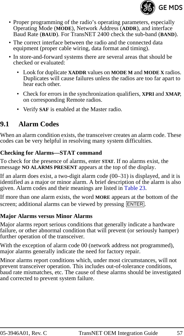
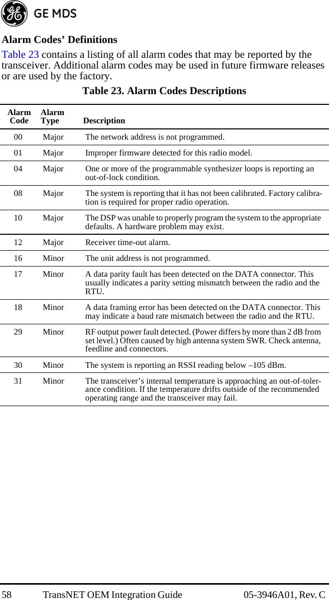
![05-3946A01, Rev. C TransNET OEM Integration Guide 619.4 Performing Network-Wide Remote DiagnosticsDiagnostics data from a Remote radio can be obtained by connecting a laptop or personal computer running MDS InSite diagnostics software (Version 6.6 or later) to any radio in the network.NOTE: The diagnostics feature may not be available in all radios. The ability to query and con-figure a radio via Network-wide Diagnostics is based on the feature options purchased in the radio being polled.If a PC is connected to any radio in the network, intrusive polling (polling which briefly interrupts payload data transmission) can be performed. To perform diagnostics without interrupting payload data transmission, connect the PC to a radio defined as the “root” radio. A radio is defined as a root radio using the DTYPE ROOT command locally, at the radio.A complete explanation of Remote diagnostics can be found in the Network-Wide Diagnostics System Handbook (Part No. 05-3467A01).1. Program one radio in the network as the root radio by entering the DTYPE ROOT command at the radio.2. At the root radio, use the DLINK ON and DLINK [baud rate] commands to configure the diagnostic link protocol on the DIAG port.3. Program all other radios in the network as nodes by entering the DTYPE NODE command at each radio.4. Use the DLINK ON and DLINK [baud rate] commands to configure the diagnostic link protocol on the RJ-11 port of each node radio.5. Connect a PC on which InSite software is installed to the root radio, or to one of the nodes, at the radio’s diagnostics port.6. Launch the InSite application at the PC. (Refer to the InSite user’s manual for details.)10.0 RADIO FIRMWARE UPGRADESFrom time to time, GE MDS releases new firmware for its radio products. This file can be installed in existing radios to take advantage of engineering improvements or additional features.Table 26. Network-Wide Diagnostics CommandsCommand DescriptionDLINK [xxxxx/ON/OFF]Details, page 44 Set baud rate of diagnostics linkDTYPE [NODE/ROOT]Details, page 45 Set radio’s operational characteristics for net-work-wide diagnostics](https://usermanual.wiki/GE-MDS/DS-EL806.User-Manual/User-Guide-1465711-Page-73.png)
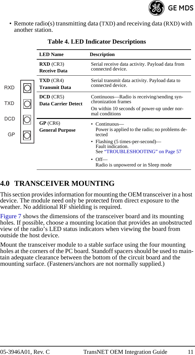
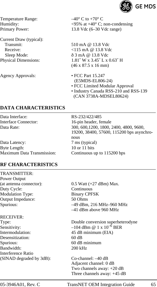
![05-3946A01, Rev. C TransNET OEM Integration Guide 632) A unique Network Address—This provides a unique identifier for each radio in a network. A radio is not addressable unless this unique code is included in the data string.3) An optional encryption value (code)—Setting an encryption code requires the use of the CODE command. This command scrambles the radio’s hop pattern and encrypts payload data content. A radio requires the correct Network Address (ADDR) and CODE value in order to synchronize. When the CODE command is used, the same value must be programmed into all radios in the network. See “CODE [NONE, 1…255]” on Page 42 for more details.The effective combination of CODE and ADDR discourage the use of an exhaustive search to gain access to a system. The items described above provide sufficient security for most systems. For highly-sensitive applications, system designers should consider employing application level encryption into their polling protocols to further protect their systems. Third party software tools are available for adding encryption, and these should be considered as part of any advanced encryption scheme.12.0 TECHNICAL REFERENCE12.1 Product Specifications—900 MHzGENERALFrequency Hopping Range: 902–928 MHz,Subdivided into eight 3.2 MHz zonesHop Pattern: Based on network addressFrequency Stability: ±1.5 ppmHalf-Duplex Operation: ±1.6 MHz TX/RX splitNetwork Addresses: 65,000Temperature Range: –40° C to +70° CHumidity: <95% at +40° C; non-condensingPrimary Power: 13.8 Vdc (6–30 Vdc range)Current Draw (typical):Transmit: 510 mA @ 13.8 VdcReceive: <115 mA @ 13.8 VdcSleep Mode: ð 3 mA @ 13.8 VdcPhysical Dimensions: 1.81˝ W x 3.45˝ L x 0.63˝ H(46 x 87.5 x 16 mm)Agency Approvals: • FCC Part 15.247 (E5MDS-EL806)• FCC Limited Modular Approval• Industry Canada RSS-210 and RSS-139 (CAN 3738A-MDSEL806)](https://usermanual.wiki/GE-MDS/DS-EL806.User-Manual/User-Guide-1465711-Page-75.png)
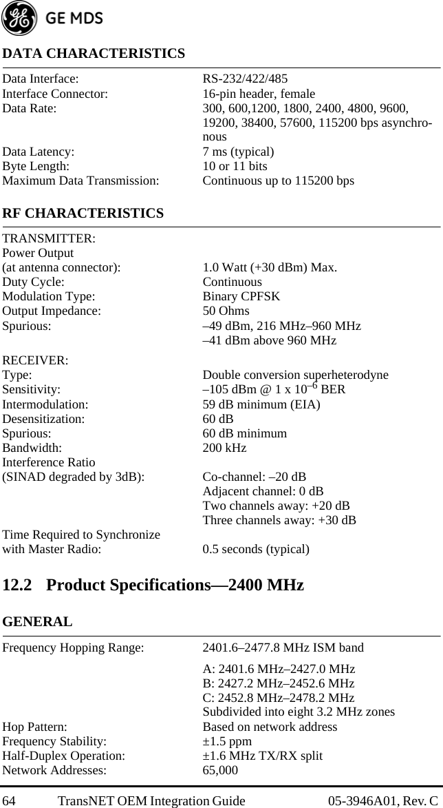
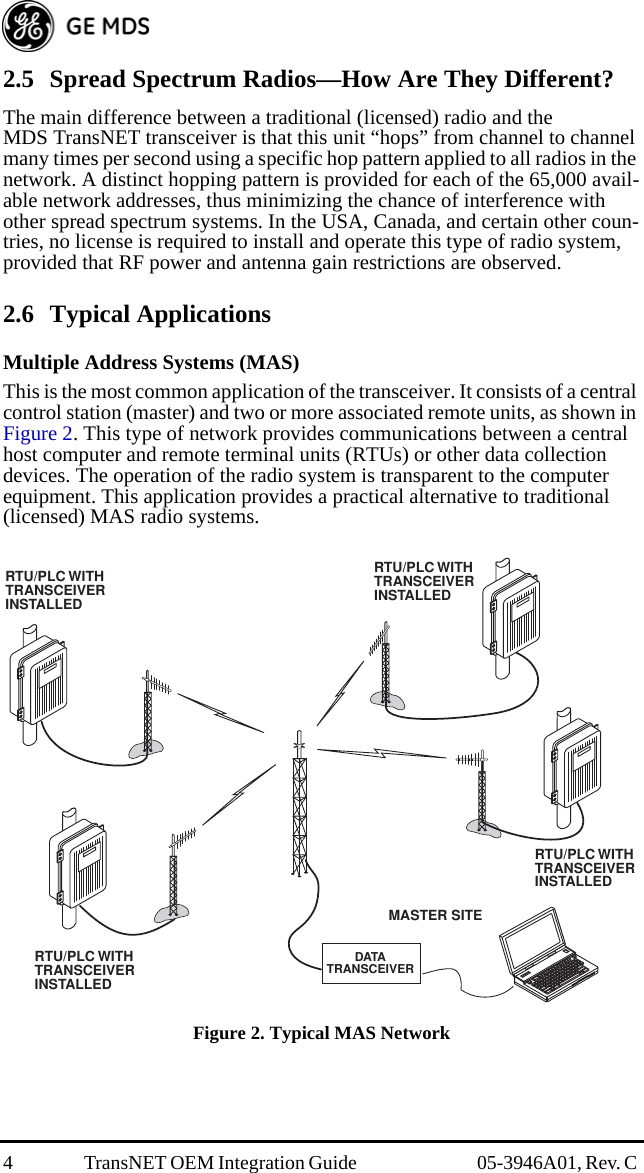
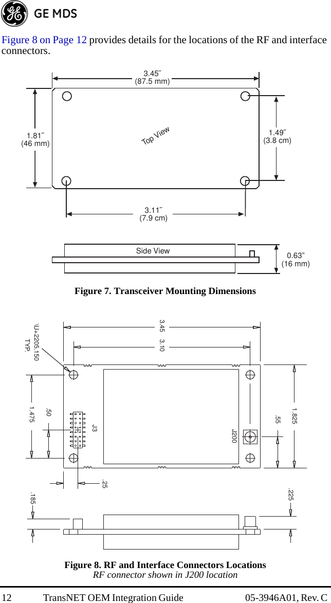
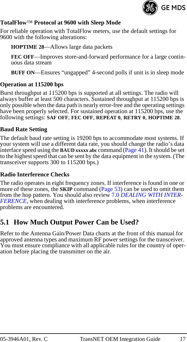
![66 TransNET OEM Integration Guide 05-3946A01, Rev. C Time Required to Synchronizewith Master Radio: 0.5 seconds (typical)12.3 Transceiver Module’s Interface Connector, J3, Detailed Pin DescriptionsThe tables in this section give detailed pin functions for the transceiver’s 16-pin header connector, J3 (see Figure 16). The tables are organized according to the available signaling configurations of the OEM transceiver. Signaling configuration is hardware fixed at the time of manufacture and will be one of the following:• TTL signaling for both Payload and Diagnostic data• Payload data TTL; Diagnostic data RS-232• Payload data RS-232/RS-485 selectable; Diagnostic data RS-232Figure 16. 16-pin Header Connector (J3) on OEM Transceiver Board(See parts list (Page80) for information on match-ing connector)Table 27. Transceiver Connector J3 Pinouts Payload data TTL; Diagnostic data TTL Pin No. Input/Output SignalType Name/Description1IN —Ground—Connects to ground (negative supply poten-tial).2 OUT TTL, 3 Vdc Diagnostic TXD—Supplies received diagnostic/ad-ministrative data to the connected device.3 OUT TTL, 3 Vdc Alarm condition—A low indicates normal operation. A high indicates an alarm. (See ASENSE [HI/LO] command for more information.)4INTTL, 3 VdcDiagnostic RXD—Accepts diagnostic/administrative data from the connected device.5IN —DC Input (6–30 Vdc)— Supply Source must be capa-ble of furnishing at least 7.5 watts.116253487691514 1312 1110](https://usermanual.wiki/GE-MDS/DS-EL806.User-Manual/User-Guide-1465711-Page-78.png)
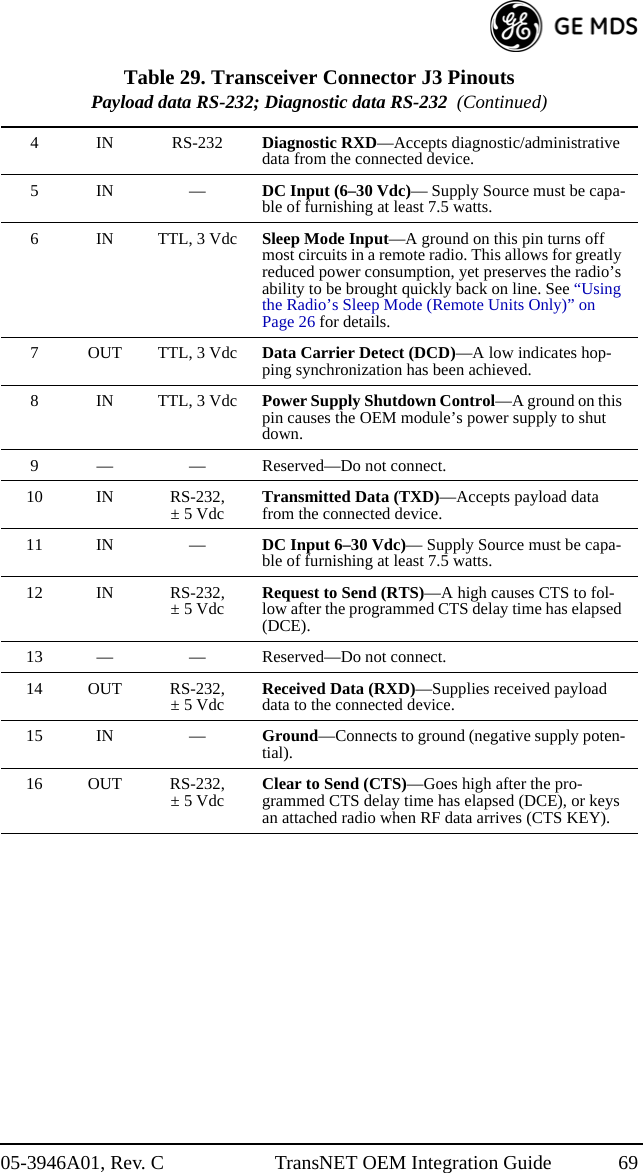
![05-3946A01, Rev. C TransNET OEM Integration Guide 676INTTL, 3 VdcSleep Mode Input—A ground on this pin turns off most circuits in a remote radio. This allows for greatly reduced power consumption, yet preserves the radio’s ability to be brought quickly back on line. See “Using the Radio’s Sleep Mode (Remote Units Only)” on Page 26 for details.7 OUT TTL, 3 Vdc Data Carrier Detect (DCD)—A low indicates hop-ping synchronization has been achieved.8INTTL, 3 VdcPower Supply Shutdown Control—A ground on this pin causes the OEM module’s power supply to shut down.9— —DC Input (Regulated 3.3 Vdc)—Supply Source must be capable of furnishing at least 7.5 watts.10 IN TTL, 3 Vdc Transmitted Data (TXD)—Accepts payload data from the connected device.11 IN — DC Input (6–18 Vdc)— Supply Source must be capa-ble of furnishing at least 7.5 watts.12 IN TTL, 3 Vdc Request to Send (RTS)—A high causes CTS to fol-low after the programmed CTS delay time has elapsed (DCE).13 — — Reserved—Do not connect.14 OUT TTL, 3 Vdc Received Data (RXD)—Supplies received payload data to the connected device.15 IN — Ground—Connects to ground (negative supply poten-tial).16 OUT TTL, 3 Vdc Clear to Send (CTS)—Goes high after the pro-grammed CTS delay time has elapsed (DCE), or keys an attached radio when RF data arrives (CTS KEY).Table 28. Transceiver Connector J3 Pinouts(Payload data TTL; Diagnostic data RS-232) Pin No. Input/Output SignalType Name/Description1IN —Ground—Connects to ground (negative supply poten-tial).2OUTRS-232Diagnostic TXD—Supplies received diagnostic/ad-ministrative data to the connected device.3 OUT TTL, 3 Vdc Alarm condition—A low indicates normal operation. A high indicates an alarm. (See ASENSE [HI/LO] command for more information.)4INRS-232Diagnostic RXD—Accepts diagnostic/administrative data from the connected device.Table 27. Transceiver Connector J3 Pinouts Payload data TTL; Diagnostic data TTL (Continued)](https://usermanual.wiki/GE-MDS/DS-EL806.User-Manual/User-Guide-1465711-Page-79.png)
![68 TransNET OEM Integration Guide 05-3946A01, Rev. C 5IN —DC Input (6–30 Vdc)— Supply Source must be capa-ble of furnishing at least 7.5 watts.6INTTL, 3 VdcSleep Mode Input—A ground on this pin turns off most circuits in a remote radio. This allows for greatly reduced power consumption, yet preserves the radio’s ability to be brought quickly back on line. See “Using the Radio’s Sleep Mode (Remote Units Only)” on Page 26 for details.7 OUT TTL, 3 Vdc Data Carrier Detect (DCD)—A low indicates hop-ping synchronization has been achieved.8INTTL, 3 VdcPower Supply Shutdown Control—A ground on this pin causes the OEM module’s power supply to shut down.9 — — Reserved—Do not connect.10 IN TTL, 3 Vdc Transmitted Data (TXD)—Accepts payload data from the connected device.11 IN — DC Input (6–30 Vdc)— Supply Source must be capa-ble of furnishing at least 7.5 watts.12 IN TTL, 3 Vdc Request to Send (RTS)—A high causes CTS to fol-low after the programmed CTS delay time has elapsed (DCE).13 — — Reserved—Do not connect.14 OUT TTL, 3 Vdc Received Data (RXD)—Supplies received payload data to the connected device.15 IN — Ground—Connects to ground (negative supply poten-tial).16 OUT TTL, 3 Vdc Clear to Send (CTS)—Goes high after the pro-grammed CTS delay time has elapsed (DCE), or keys an attached radio when RF data arrives (CTS KEY).Table 29. Transceiver Connector J3 PinoutsPayload data RS-232; Diagnostic data RS-232 Pin No. Input/Output SignalType Name/Description1IN —Ground—Connects to ground (negative supply poten-tial).2OUTRS-232Diagnostic TXD—Supplies received diagnostic/ad-ministrative data to the connected device.3 OUT TTL, 3 Vdc Alarm condition—A low indicates normal operation. A high indicates an alarm. (See ASENSE [HI/LO] command for more information.)Table 28. Transceiver Connector J3 Pinouts(Payload data TTL; Diagnostic data RS-232) (Continued)](https://usermanual.wiki/GE-MDS/DS-EL806.User-Manual/User-Guide-1465711-Page-80.png)
![70 TransNET OEM Integration Guide 05-3946A01, Rev. C Table 30. Transceiver Connector J3 PinoutsPayload data RS-485; Diagnostic data RS-232 Pin No. Input/Output SignalType Name/Description1IN —Ground—Connects to ground (negative supply poten-tial).2OUT RS-232Diagnostic TXD—Supplies received diagnostic/ad-ministrative data to the connected device.3 OUT TTL, 3 Vdc Alarm condition—A low indicates normal operation. A high indicates an alarm. (See ASENSE [HI/LO] command for more information.)4IN RS-232Diagnostic RXD—Accepts diagnostic/administrative data from the connected device.5IN —DC Input (6–30 Vdc)— Supply Source must be capa-ble of furnishing at least 7.5 watts.6INTTL, 3 VdcSleep Mode Input—A ground on this pin turns off most circuits in a remote radio. This allows for greatly reduced power consumption, yet preserves the radio’s ability to be brought quickly back on line. See “Using the Radio’s Sleep Mode (Remote Units Only)” on Page 26 for details.7 OUT TTL, 3 Vdc Data Carrier Detect (DCD)—A low indicates hop-ping synchronization has been achieved.8INTTL, 3 VdcPower Supply Shutdown Control—A ground on this pin causes the OEM module’s power supply to shut down.9 — — Reserved—Do not connect.10 IN Differential RXD+/RXA (Transmitted Data+)—Non-inverting receiver input. Accepts payload data from the connect-ed device.11 IN — DC Input (6–30 Vdc)— Supply Source must be capa-ble of furnishing at least 7.5 watts.12 IN Differential RXD–/RXA (Transmitted Data-)—Inverting receiv-er input.13 — — Reserved—Do not connect.14 OUT Differential TXD+/TXA (Received Data+)—Non-inverting driver output. Supplies received payload data to the connect-ed device.15 IN — Ground—Connects to ground (negative supply poten-tial).16 OUT Differential TXD–/TXA (Received Data-)—Inverting driver out-put.](https://usermanual.wiki/GE-MDS/DS-EL806.User-Manual/User-Guide-1465711-Page-82.png)