GE MDS DS-EL806 EL806 OEM Transnet User Manual 95 00 0 xxx sngl page print
GE MDS LLC EL806 OEM Transnet 95 00 0 xxx sngl page print
UserManual.wiki
>
GE MDS
>
DS-EL806 User Manual
>
Host User Manual
Contents
1.
users manual
2.
Host User Manual
3.
User Manual
Host User Manual
Navigation menu
Upload a User Manual
Namespaces
Wiki Guide
HTML
PDF
Info
Views
User Manual
Discussion / Help
Navigation


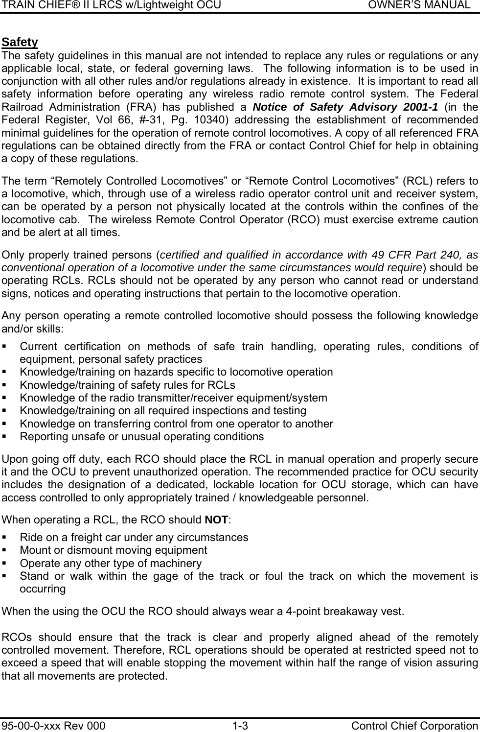
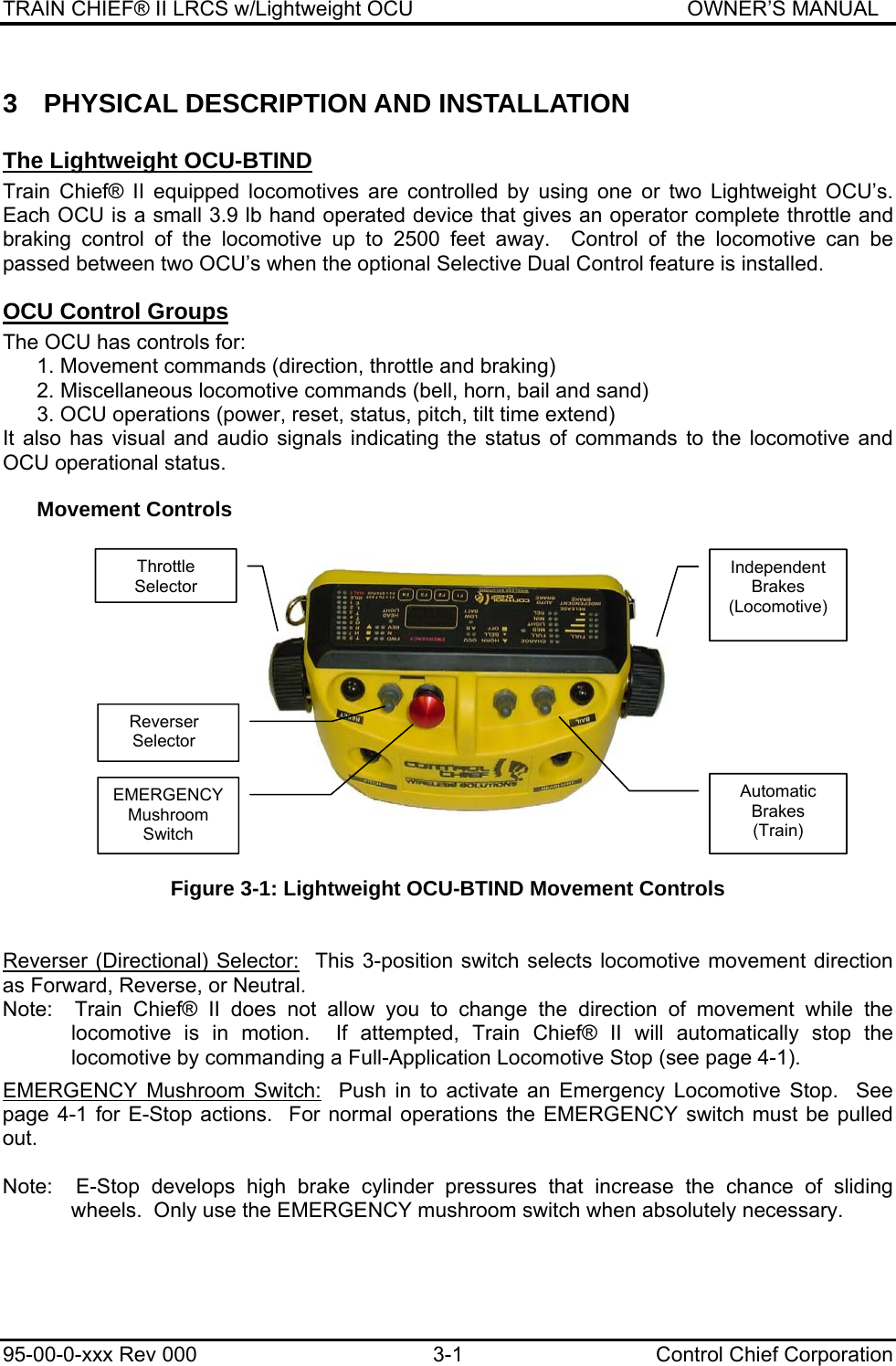
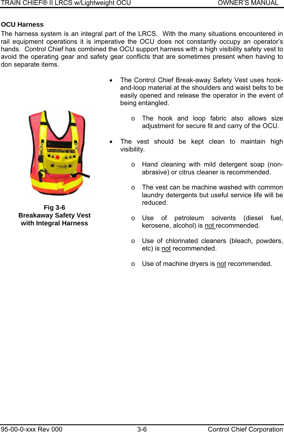
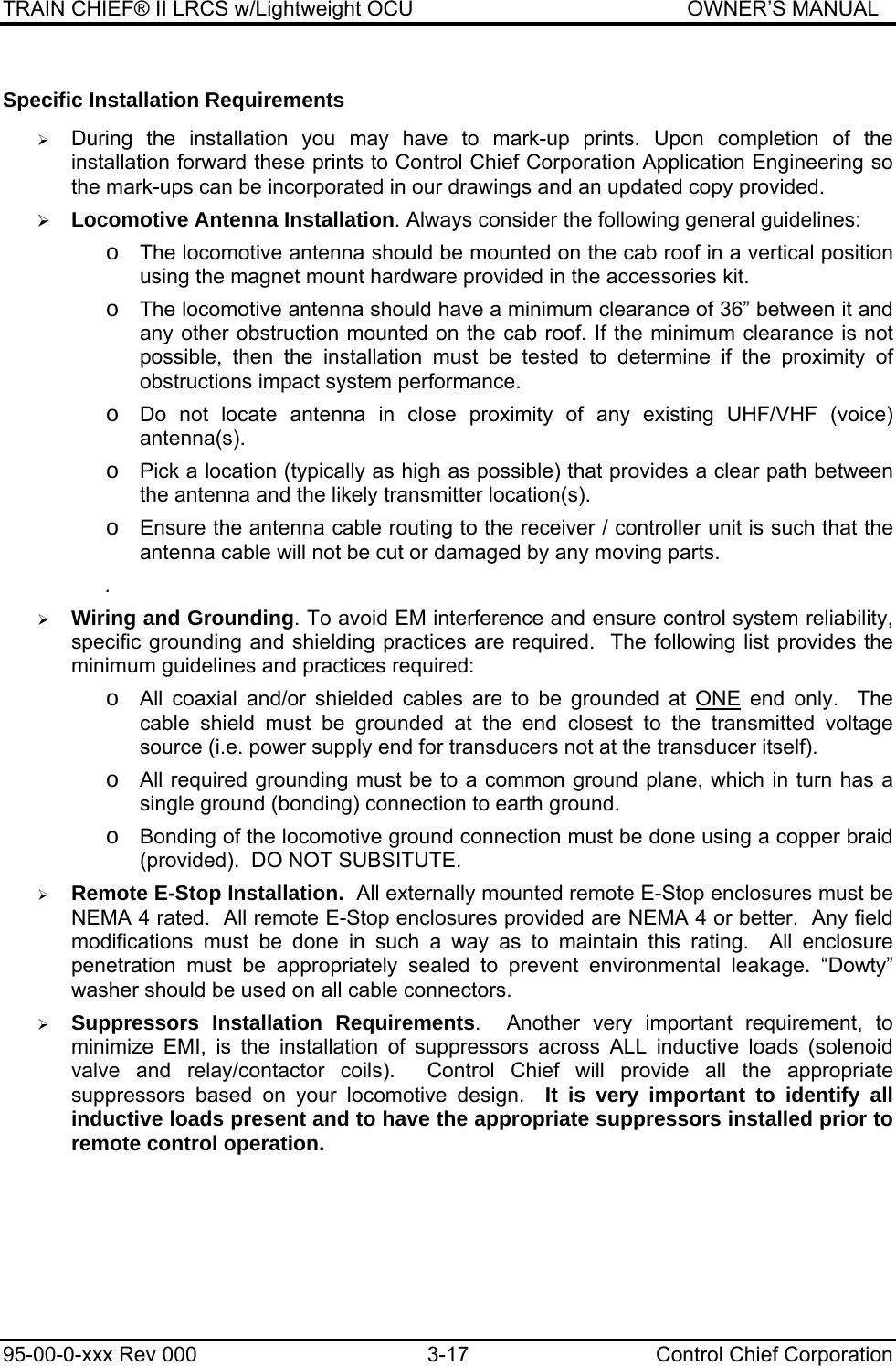
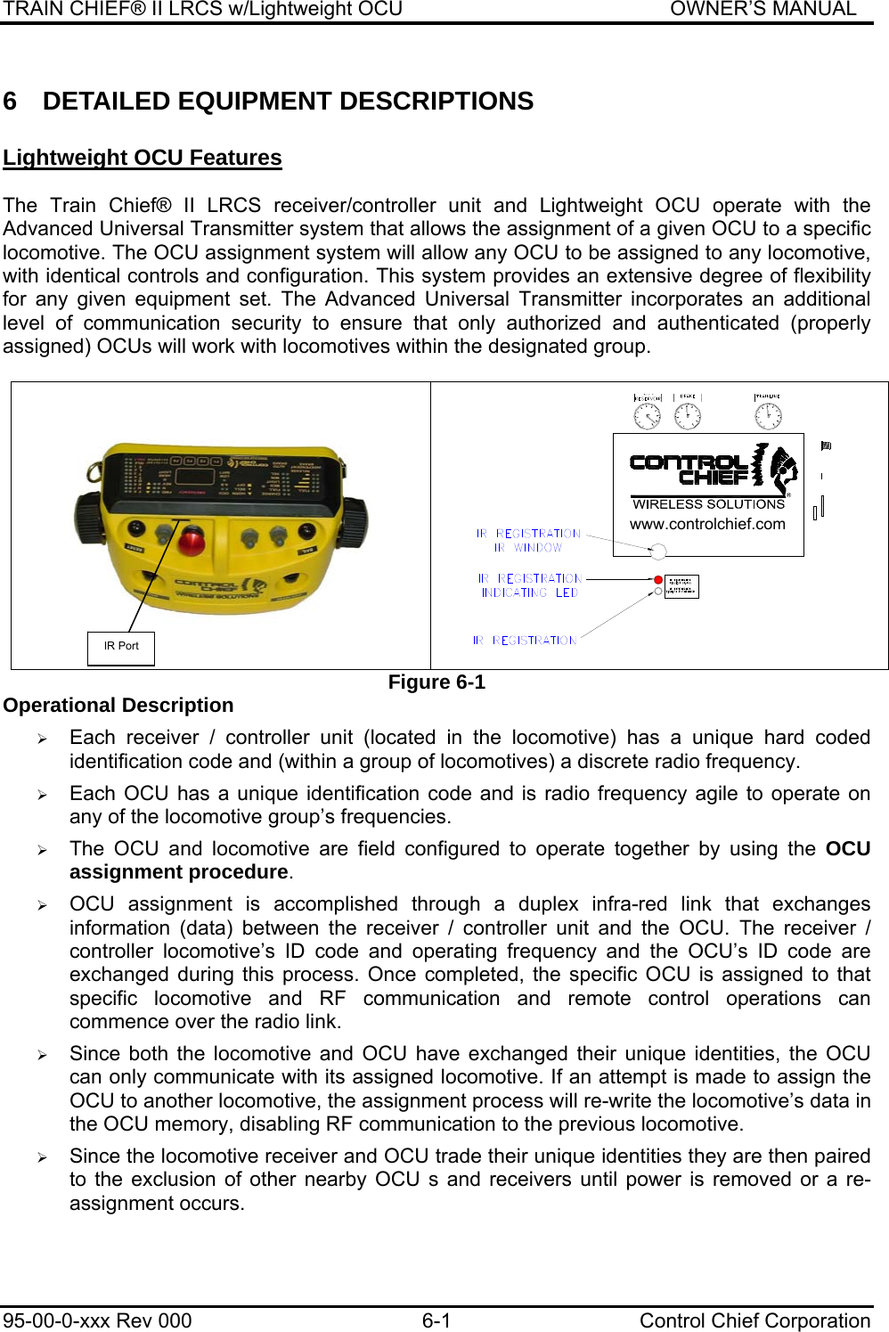
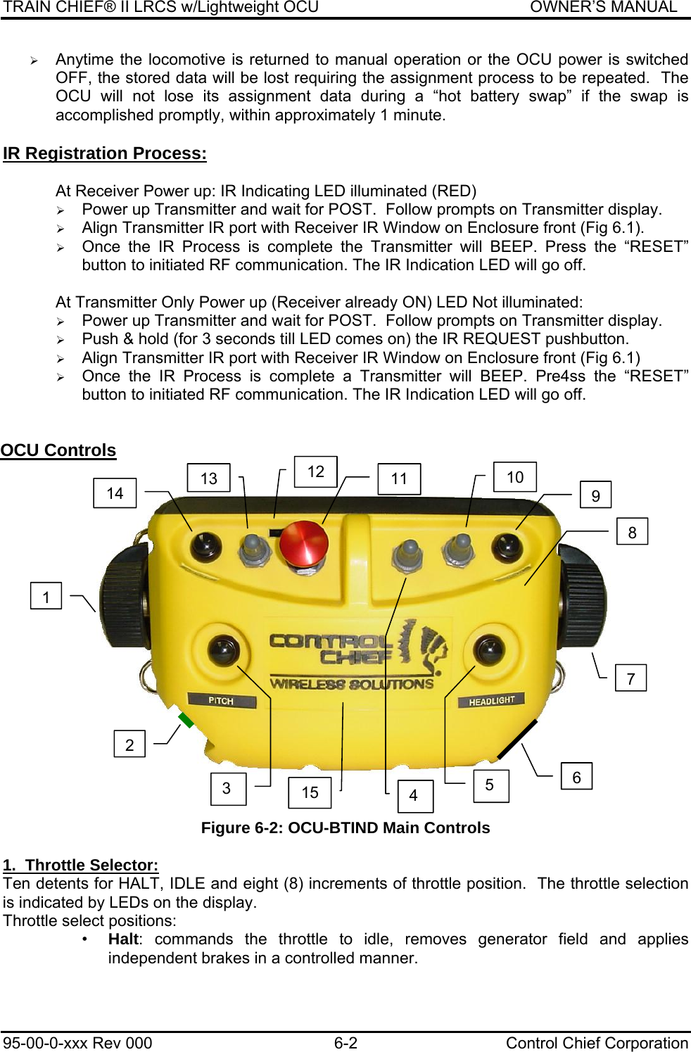
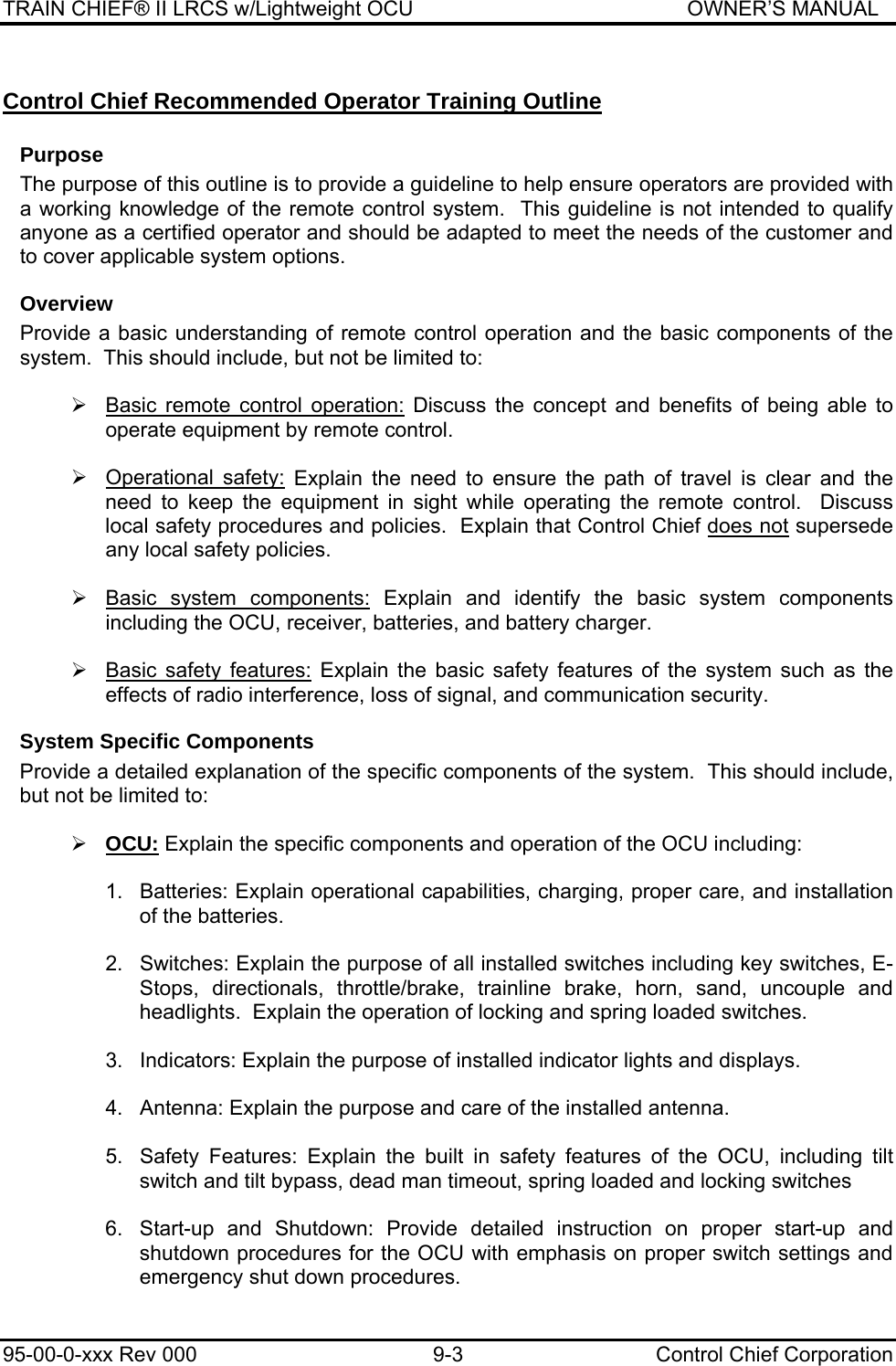
![TRAIN CHIEF® II LRCS w/Lightweight OCU OWNER’S MANUAL 95-00-0-xxx Rev 000 3-5 Control Chief Corporation OCU Keypad, Indicators and Display The location of the LEDs, Character-display, and Intensity sensor are shown in the diagram below. All LEDs will illuminate during the power on sequence to allow detection of inoperative LEDs. Figure 3-4: Display Panel for Brake-Throttle Unit [A] Independent Brakes [E] Headlight Bright Indicator [B] Auto Brakes [F] 16 Character Display [C] Reverser [G] Low Battery Indicator [D] Throttle [H] OCU A / B Indicator [J] Ambient Light Sensor Steady LEDs at the respective locations in the above figure show the selected positions of the OCU controls. Battery Compartment The 7.4 volt Lithium-Ion battery is secured in the compartment by its own locking lip and does not require a latching cover. Additional details are described on page 6-1. Fig 3-5: Battery and Battery Well A B J C HD GFE](https://usermanual.wiki/GE-MDS/DS-EL806.Host-User-Manual/User-Guide-1465710-Page-15.png)