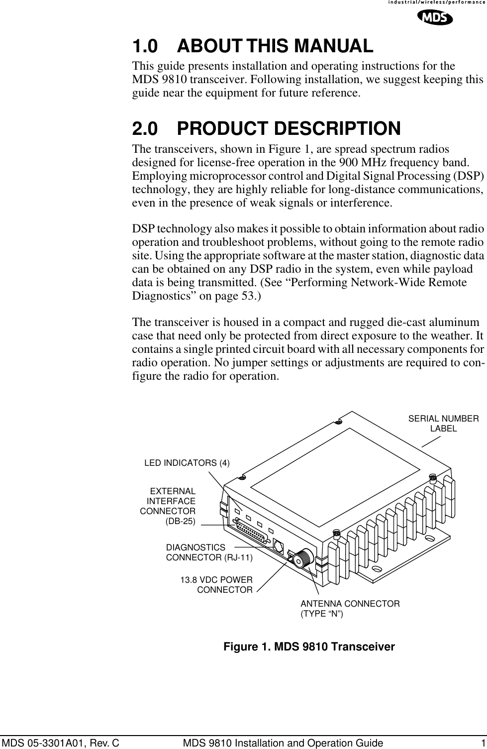
GE MDS DS-9810 Spread Spectrum Data Tranceiver User Manual Manual revision 2
GE MDS LLC Spread Spectrum Data Tranceiver Manual revision 2
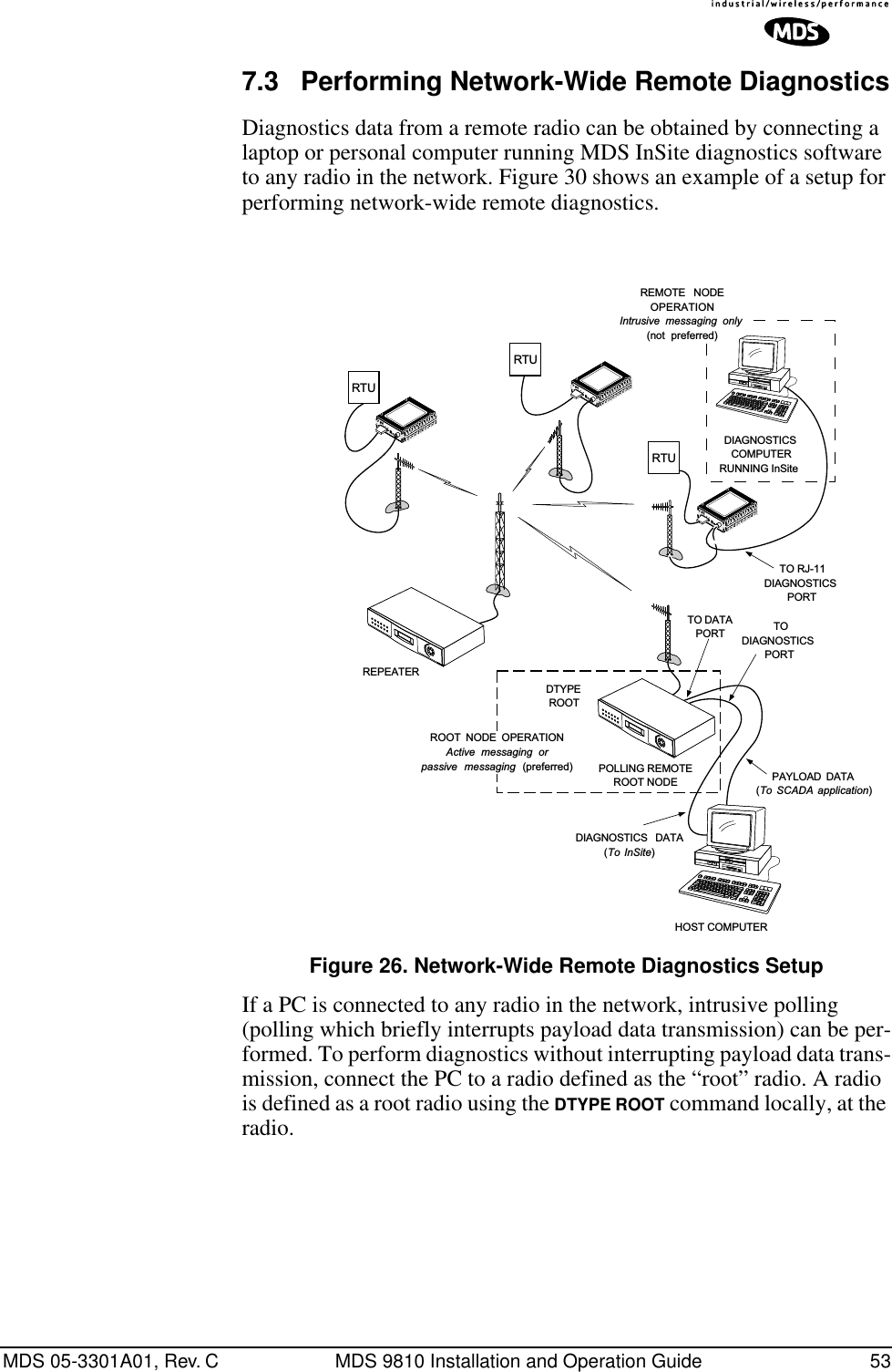
GE MDS >
Contents
- 1. Manual rf statement
- 2. Manual revision 2
- 3. Users Manual
Manual revision 2
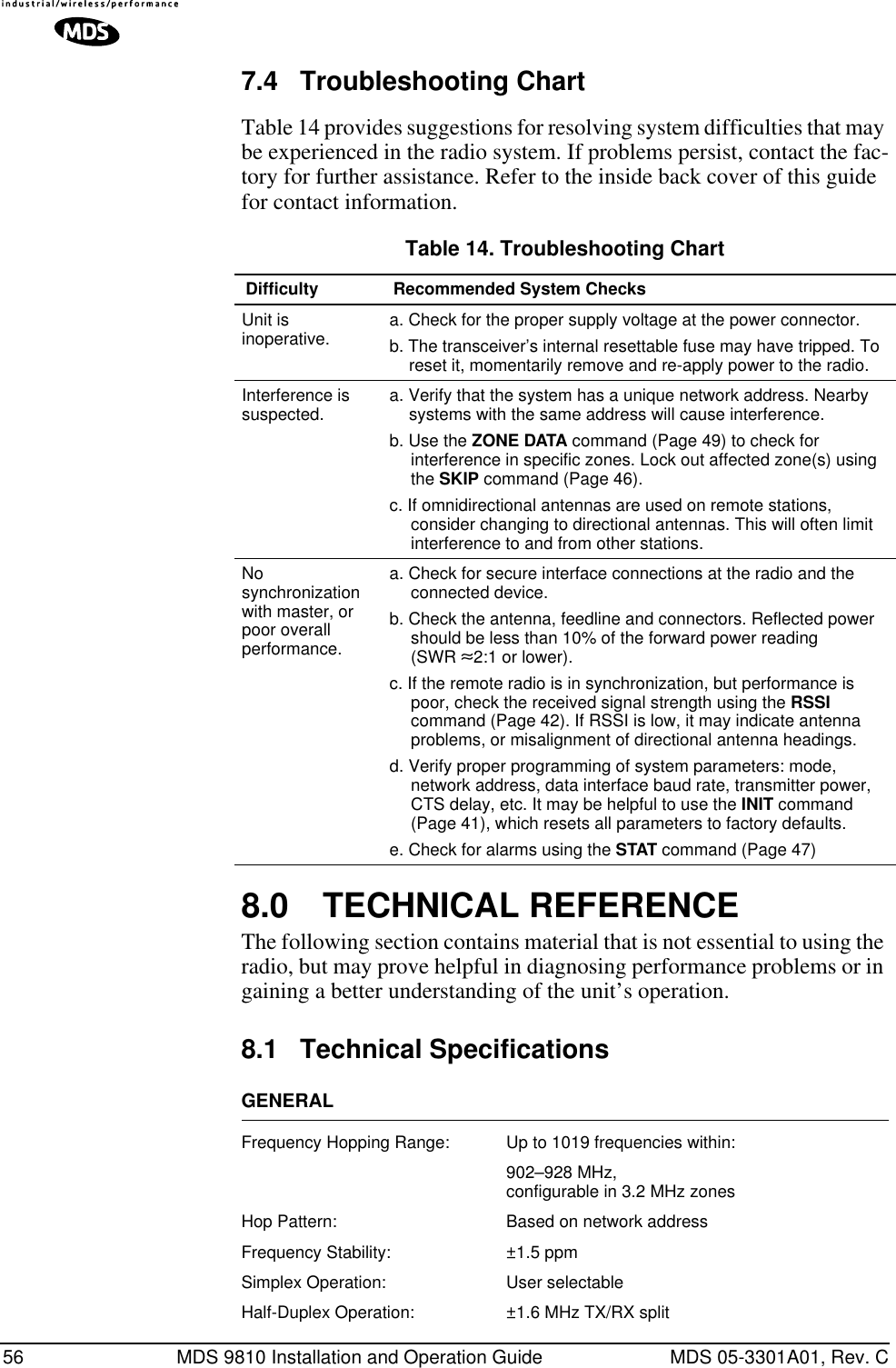
![ii MDS 9810 Installation and Operation Guide MDS 05-3301A01, Rev. C4.5 “Single-Radio” Repeater—Alternative Method ............................................................................24Interface Wiring..............................................................................................................................24Software Programming (TDD Command)......................................................................................24Limitations of Single-Radio Repeaters...........................................................................................254.6 Using the Radio’s Sleep Mode ....................................................................................................25Sleep Mode Example.....................................................................................................................25 5.0 OPERATION ....................................................................................................................... 26 5.1 Initial Start-up ..............................................................................................................................265.2 Performance Optimization ...........................................................................................................26Antenna Aiming..............................................................................................................................27Antenna SWR Check.....................................................................................................................27Data Buffer Setting.........................................................................................................................27Hoptime Setting .............................................................................................................................27Baud Rate Setting..........................................................................................................................28Radio Interference Checks.............................................................................................................28 6.0 PROGRAMMING................................................................................................................ 28 6.1 Hand-Held Terminal Connection & Start-up ................................................................................286.2 Hand-Held Terminal Setup ..........................................................................................................296.3 Keyboard Commands ..................................................................................................................30Entering Commands ......................................................................................................................30Error Messages..............................................................................................................................316.4 Detailed Command Descriptions .................................................................................................35ADDR [1...65000]...........................................................................................................................36AMASK [0000 0000–FFFF FFFF]..................................................................................................36ASENSE [HI/LO]............................................................................................................................36BAUD [xxxxx abc] ..........................................................................................................................36BUFF [ON, OFF]............................................................................................................................37CTS [0–255]...................................................................................................................................37CTSHOLD [0-6000]........................................................................................................................38DEVICE [DCE, CTS KEY].............................................................................................................38DLINK [xxxxx] ................................................................................................................................39DMGAP [xx] ...................................................................................................................................39DTYPE [NODE/ROOT/GATE/PEER] .............................................................................................39HOPTIME [XSHORT, 16, 20, 25, 32, SHORT, NORMAL, LONG] .................................................40INIT ................................................................................................................................................41MODE [M, R, R-M].........................................................................................................................41OWM [xxxxx]..................................................................................................................................42OWN [xxxxx] ..................................................................................................................................42PWR [xx–30]..................................................................................................................................42RSSI...............................................................................................................................................42RTU [ON/OFF/0-80].......................................................................................................................43RX [xxxx]........................................................................................................................................43RXTOT [NONE, 0–1440]................................................................................................................43SEND [n, -n, +n].............................................................................................................................43SETUP...........................................................................................................................................44SHOW [PORT, DC, PWR]..............................................................................................................45SIMPLEX [ON, OFF]......................................................................................................................45](https://usermanual.wiki/GE-MDS/DS-9810.Manual-revision-2/User-Guide-457660-Page-4.png)
![MDS 05-3301A01, Rev. C MDS 9810 Installation and Operation Guide iiiSKIP [NONE, 1...8] ........................................................................................................................46SKIPSYNC [ON/OFF] ....................................................................................................................46SNR ...............................................................................................................................................46SREV .............................................................................................................................................47STAT...............................................................................................................................................47TDD [ON/OFF]...............................................................................................................................47TEMP.............................................................................................................................................48TX [xxxx] ........................................................................................................................................48UNIT [10000–65000]......................................................................................................................48ZONE DATA ...................................................................................................................................49ZONE CLEAR................................................................................................................................50 7.0 TROUBLESHOOTING ........................................................................................................ 50 7.1 LED Indicators .............................................................................................................................507.2 Alarm Codes ................................................................................................................................51Checking for Alarms—STAT command..........................................................................................51Major Alarms vs. Minor Alarms ......................................................................................................51Alarm Code Definitions ..................................................................................................................527.3 Performing Network-Wide Remote Diagnostics ..........................................................................53DLINK [xxxxx] ................................................................................................................................55DTYPE [NODE/ROOT/GATE/PEER] .............................................................................................557.4 Troubleshooting Chart .................................................................................................................56 8.0 TECHNICAL REFERENCE................................................................................................. 56 8.1 Technical Specifications ..............................................................................................................568.2 RSSI Checks with a Voltmeter .....................................................................................................588.3 Data Interface Connections (DB-25) ...........................................................................................588.4 Bench Testing Setup ....................................................................................................................618.5 Using Radio Configuration Software ...........................................................................................61Connecting a PC............................................................................................................................62Upgrading the Radio’s Software ....................................................................................................628.6 dBm-Watts-Volts Conversion Chart .............................................................................................63 9.0 GLOSSARY OF TERMS..................................................................................................... 63 Copyright Notice This Installation and Operation Guide and all software described herein are protected by copy-right: 2004 Microwave Data Systems Inc. All rights reserved.Microwave Data Systems reserves its right to correct any errors and omissions in this document.](https://usermanual.wiki/GE-MDS/DS-9810.Manual-revision-2/User-Guide-457660-Page-5.png)
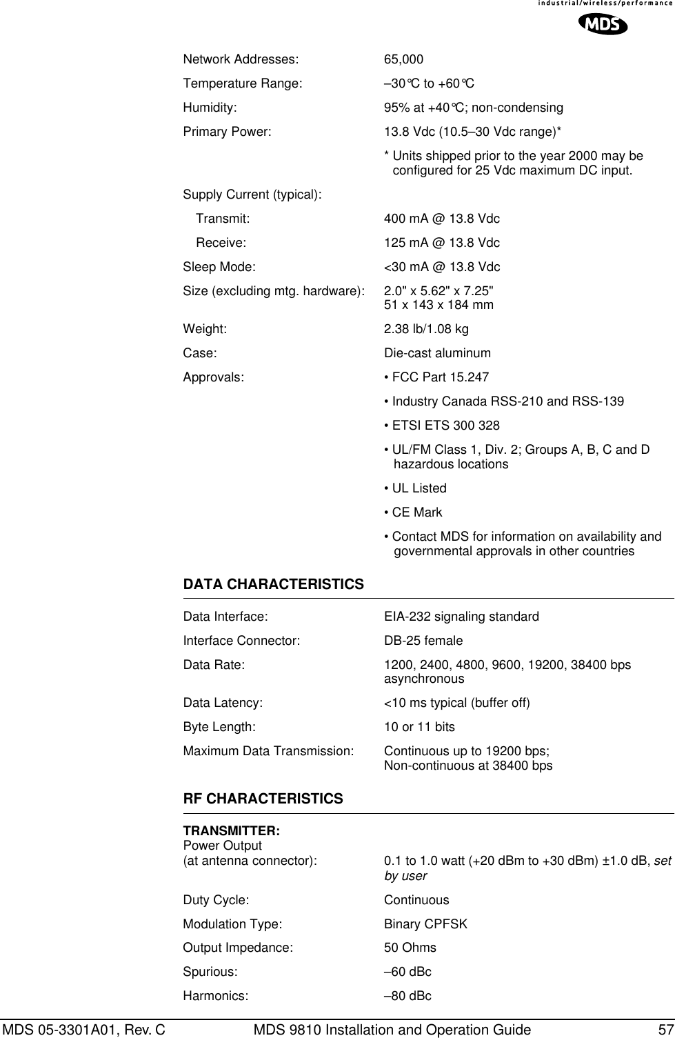
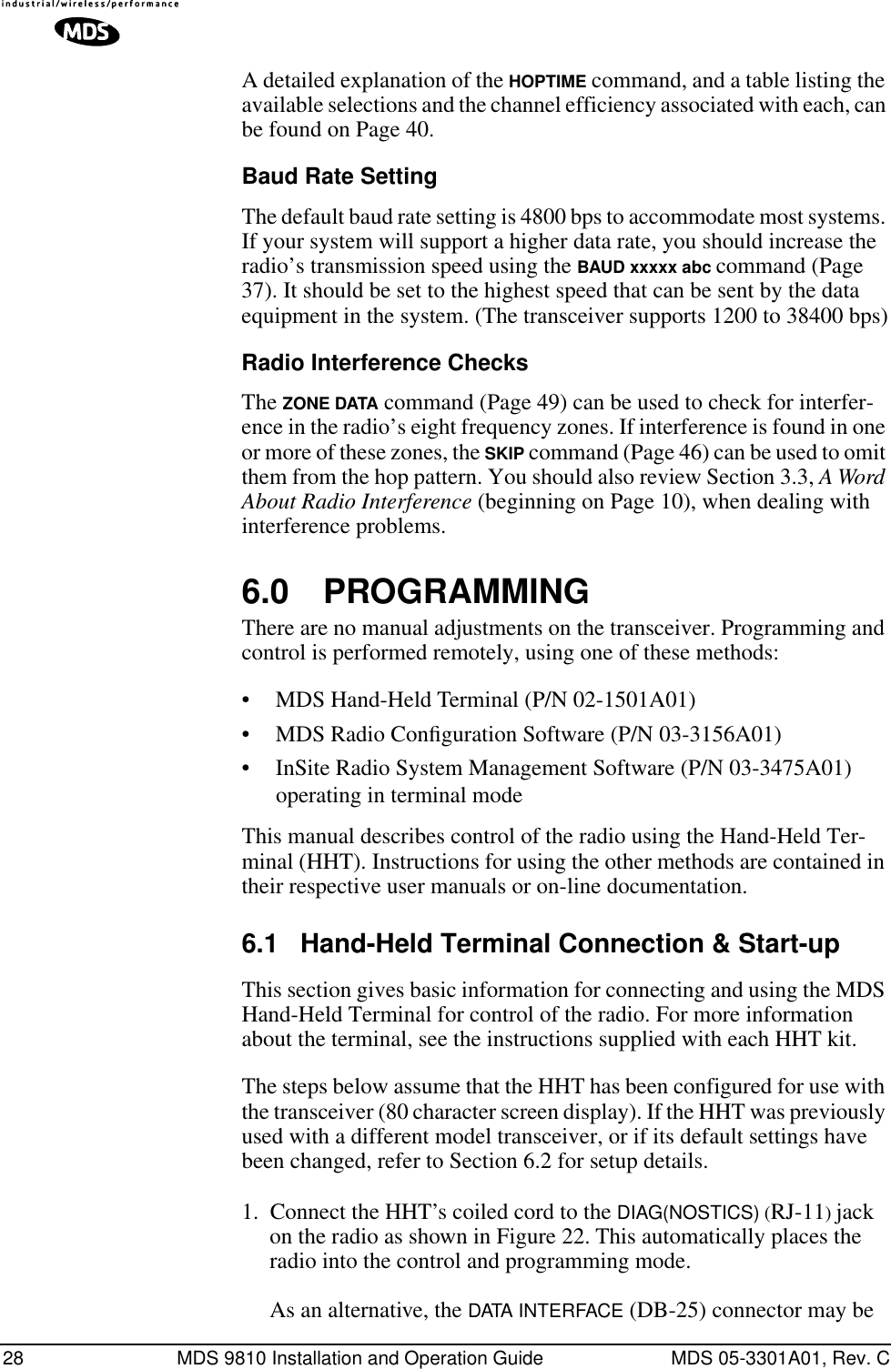
![MDS 05-3301A01, Rev. C MDS 9810 Installation and Operation Guide 23AntennasTwo antennas are required at repeater stations—one for each radio. Measures must be taken to minimize the chance of interference between these antennas. One effective technique for limiting interference is to employ vertical separation. In this arrangement, one antenna is mounted directly over the other, separated by at least 10 feet (3 Meters). This takes advantage of the minimal radiation exhibited by most antennas directly above and below their driven elements.Another interference reduction technique is to cross-polarize the repeater antennas. If one antenna is mounted in the vertical plane, and the other in the horizontal plane, an additional 20 dB of attenuation can be achieved. (Remember that the corresponding stations must use the same antenna orientation when cross-polarization is used.)System AddressesThe two radios that are wired together at the repeater site must have dif-ferent system addresses. To set or view the system address, see “ADDR [1...65000]” on page 36.Interface WiringA null-modem cable (Figure 19) is required between the DATA INTER-FACE connectors of the two radios forming a repeater station. This allows them to freely exchange data even though they are both config-ured as DCE devices.Invisible place holderFigure 19. Data Interface Cable Wiring for Null-Modem Cable(used for traditional repeater)Diagnostic LimitationsAs of the date of publication, over-the-air diagnostics is not fully sup-ported in repeater systems. Diagnostic data from these systems may be unavailable or unreliable. This is particularly true if a repeater radio is configured as the “root” in a diagnostics scheme (See “Performing Net-work-Wide Remote Diagnostics” on page 53.) Better success might be achieved by picking a standard remote to use as the root.DB-25 DB-25Spread Spectrum Master(DCE)237327Spread Spectrum Remote(DCE)TXDRXDGNDRXDTXDGND](https://usermanual.wiki/GE-MDS/DS-9810.Manual-revision-2/User-Guide-457660-Page-31.png)
![32 MDS 9810 Installation and Operation Guide MDS 05-3301A01, Rev. CTable 6. Command Summary COMMAND DESCRIPTION NETWORKCONFIGURATIONThese programming commandscan only be set at the master radio.BUFF [ON, OFF] Details Page 37 ON = Seamless data, OFF = Fast byte through-put.HOPTIME [XSHORT, 16, 20, 25, 32, SHORT, NORMAL, LONG] Details Page 40Select hop time—XSHORT, 16 ms, 20 ms, 25 ms, 32 ms, SHORT, NORMAL, LONGSEND [n, -n, +n] Details Page 43Sets/displays re-send count for data packets. Useful in areas with heavy radio interference.SIMPLEX [ON, OFF] Details Page 45 Program simplex/half-duplex selection.ON = simplex, OFF = half-duplexSKIP [NONE, 1...8] Details Page 46 Select combination of frequency operating zones to avoid.SKIPSYNC [ON/OFF] Details Page 46 May be used to suppress transmission of SYNC messages in skipped zones. (See also SKIP command). Default setting is OFF.TDD [ON/OFF] Details Page 47 Sets or displays time-division multiplex status of DATA INTERFACE connector. (Sometimes referred to as “simulated full-duplex” mode.)NETWORK-WIDEDIAGNOSTICSCONFIGURATIONDLINK [xxxxx] Details Page 39 Set baud rate of diagnostics linkDTYPE [NODE/ROOT/GATE/PEER] Details Page 39Set radio’s operational characteristics for net-work-wide diagnosticsUNIT [10000–65000] Details Page 48 Program unit address. Used to set a unique address for network-wide diagnostics.](https://usermanual.wiki/GE-MDS/DS-9810.Manual-revision-2/User-Guide-457660-Page-40.png)
![MDS 05-3301A01, Rev. C MDS 9810 Installation and Operation Guide 33SET/PROGRAM COMMANDSADDR [1...65000] Details Page 36 Program network addressAMASK [0000 0000–FFFF FFFF] Details Page 36Sets alarm response. Default is FFFF FFFF. ASENSE [HI/LO] Details Page 36 Changes the sense of the alarm output. Default sense is HI. BAUD [xxxxx abc] Details Page 36 Set data communication parametersCTS [0–255] Details Page 37 Program CTS delay in milliseconds.(A value of 0 returns CTS immediately)CTSHOLD [0-6000] Details Page 38 Set/display “hold time” that CTS remains present following last character transmission from DD-25 port.DEVICE [DCE, CTS KEY] Details Page 38 Set device behavior; DCE (normal) or CTS Key (Repeater)INIT Details Page 41 Initialize parameters to factory default valuesMODE [M, R, R-M] Details Page 41 Program operating mode, where M = Master,R = Remote, R-M = Remote-Master (Remote radio programmed to operate on Master fre-quencies)OWM [xxxxx] Details Page 42 Program owner’s message(30 characters maximum)OWN [xxxxx] Details Page 42 Program owner’s name(30 characters maximum)PWR [xx–30] Details Page 42 Program forward power output in dBm.RTU [ON/OFF/0-80] Details Page 43 Re-enables or disables the radio’s internal RTU simulator and sets the RTU address.RXTOT [NONE, 0–1440] Details Page 43 Specifies max. duration (in minutes) to wait before issuing a time-out alarm. Default is OFF. SEND [n, -n, +n] Details Page 43Sets/displays re-send count for data packets. Useful in areas with heavy radio interference.TDD [ON/OFF] Details Page 47 Sets or displays time-division multiplex status of DATA INTERFACE connector. (Sometimes referred to as “simulated full-duplex” mode.)UNIT [10000–65000] Details Page 48 Program unit address. Used to set a unique address for network-wide diagnostics.ZONE DATA Details Page 49 Show zone data statistics. Press “Q” to quitZONE CLEAR Details Page 50 Reset zone data statisticsTable 6. Command Summary (Continued)COMMAND DESCRIPTION](https://usermanual.wiki/GE-MDS/DS-9810.Manual-revision-2/User-Guide-457660-Page-41.png)
![34 MDS 9810 Installation and Operation Guide MDS 05-3301A01, Rev. CDISPLAY OPERATING STATUSADDR [1...65000] Details Page 36 Network address (1-65000)AMASK [0000 0000–FFFF FFFF] Details Page 36Sets alarm mask (response). Default is FFFF FFFF.ASENSE [HI/LO] Details Page 36 Changes the sense of the alarm output. Default sense is HI.BAUD [xxxxx abc] Details Page 36 Display data communication parameters. Example: BAUD 9600 8N1BUFF [ON, OFF] Details Page 37 Data buffering mode: ON = seamless dataOFF = fast byte throughputCTS [0–255] Details Page 37 CTS delay in ms (0-255 ms)DUMP Show all settings. Use with PC-based Radio Configuration software (P/N 03-3156A01).DEVICE [DCE, CTS KEY] Details Page 38 Device behavior (DCE, or CTS KEY)HOPTIME [XSHORT, 16, 20, 25, 32, SHORT, NORMAL, LONG] Details Page 40Show hop time in milliseconds (ms).HREV Hardware revision levelMODE [M, R, R-M] Details Page 41 Show operating mode: M = Master, R = Remote, R-M = Remote-Master (remote oper. on master freqs.)OWM Owner’s message or site nameOWN Owner’s name or system namePWR [xx–30] Details Page 42 Forward power output setting in dBmRSSI Details Page 42 Received signal strength in dBm (continuously updated). Not available at master radio unless SETUP is enabled.RXTOT [NONE, 0–1440] Details Page 43 Specifies amount of time (in seconds) to wait before issuing a time-out alarm. Default is NONE. SEND [n, -n, +n] Details Page 43Sets/displays re-send count for data packets. Useful in areas with heavy radio interference.SER Serial number of radioSHOW [PORT, DC, PWR] Details Page 45 Show active port, DC voltage or measured RF power (dBm)SIMPLEX [ON, OFF] Details Page 45 Simplex/half-duplex selectionON = Simplex, OFF = half-duplexSKIP [NONE, 1...8] Details Page 46 Skip a frequency operating zoneSKIPSYNC [ON/OFF] Details Page 46 When ON, suppresses transmission of SYNC messages in skipped zones. Default setting is OFF.Display parameters continued...Table 6. Command Summary (Continued)COMMAND DESCRIPTION](https://usermanual.wiki/GE-MDS/DS-9810.Manual-revision-2/User-Guide-457660-Page-42.png)
![MDS 05-3301A01, Rev. C MDS 9810 Installation and Operation Guide 356.4 Detailed Command DescriptionsThe essential commands for most applications are Network Address (ADDR), Mode, (MODE) and Baud Rate (BAUD). However, proper use of the additional commands allows you to tailor the transceiver for a spe-cific use, or to conduct basic diagnostics on the radio. This section gives more detailed information for many of the user commands listed in Table 6.Most of the commands below can be used in two ways. First, you can type only the command name (for example, ADDR) to view the currently programmed data. Second, you can set or change the existing data by typing the command, followed by a space, and then the desired entry (for example, ADDR 1234). In the list below, allowable programming variables, if any, are shown in brackets [ ] following the command name.DISPLAY OPERATING STATUS(CONTINUED)SNR Details Page 46 Signal-to-noise ratio. Expressed in dB.SREV Details Page 47Display transceiver firmware revision levelSTAT Details Page 47 Show current alarm statusTDD [ON/OFF] Details Page 47 Sets or displays time-division multiplex status of DATA INTERFACE connector. (Sometimes referred to as “simulated full-duplex” mode.)TEMP Details Page 48 Transceiver’s internal temperature (°C)UNIT [10000–65000] Details Page 48 Show programmed unit address for net-work-wide diagnosticsZONE DATA Details Page 49 Show zone data statistics (see text for details). Press “Q” to quit.DIAGNOSTIC/TESTKEY Enables the transmitter. (Radio must be in Setup mode.)DKEY Disables the transmitter. (Radio must be in Setup mode.)DMGAP [xx] Details Page 39 Sets the amount of time to wait after the receipt of a character before interpreting the next received character as the start of a new message.TX [xxxx] Details Page 48 Set/display transmit test frequency. (Radio must be in Setup mode.)RX [xxxx] Details Page 43 Set/display receive test frequency. (Radio must be in Setup mode.)SETUP Details Page 44 Enables Setup mode. Times out after 15 min-utes. Press “Q” to quit.Table 6. Command Summary (Continued)COMMAND DESCRIPTION](https://usermanual.wiki/GE-MDS/DS-9810.Manual-revision-2/User-Guide-457660-Page-43.png)
![36 MDS 9810 Installation and Operation Guide MDS 05-3301A01, Rev. CADDR [1...65000]This command sets or displays the radio’s network address. The net-work address can range from 1 to 65000.Network address must be programmed at the time of installation and must be common across each radio in a given network. Radios are typi-cally shipped with the network address unprogrammed. This causes the address to display as NONE. This leaves the system in an invalid state and prevents operation.NOTE: It is recommended that the last four digits of the master radio’sserial number be used for the network address (or chassis serialnumber if the radio is installed in a P-20 redundant chassis).AMASK [0000 0000–FFFF FFFF]This command sets the alarm bits that cause the alarm output signal to be triggered. The PWR LED will still flash for all alarms, but the alarm output signal will only be activated for those alarms that have the corre-sponding mask bit set. The hex value for the mask aligns directly with the hex value for the ALARM command. The default is FFFF FFFF. Through proper use of the AMASK command, it is possible to tailor the alarm response of the radio. Contact the factory for more information on configuring the alarm mask.ASENSE [HI/LO]This command is used to set or display the sense of the alarm output at Pin 25 of the DATA INTERFACE connector. The default for transceivers is active HI.BAUD [xxxxx abc]This command sets or displays the communication attributes for the DATA INTERFACE port. The command has no effect on the RJ-11 DIAG(NOSTICS) port.The first parameter (xxxxx) is baud rate. Baud rate is specified in bits-per-second and must be one of the following speeds: 1200, 2400, 4800, 9600, 19200, or 38400. In the worst case, the radio will always accept a minimum of 500 data bytes in a single continuous data trans-mission. At baud rates of 4800 bps or less, the radio can support unlim-ited continuous data transmission at any hop rate. If hop time is set to NORMAL or LONG, baud rates of up to 19200 bps with continuous unlim-ited data transmission are possible. (See HOPTIME command.)The second parameter of the BAUD command (abc) is a 3-character block indicating how the data is encoded. The following is a breakdown of each character’s meaning:](https://usermanual.wiki/GE-MDS/DS-9810.Manual-revision-2/User-Guide-457660-Page-44.png)
![MDS 05-3301A01, Rev. C MDS 9810 Installation and Operation Guide 37a = Data bits (7 or 8)b = Parity (N for None, O for Odd, E for Even)c = Stop bits (1 or 2)The factory default setting is 4800 baud, 8 data bits, no parity, 1 stop bit (Example: 4800 8N1).NOTE: 7N1, 8O2, and 8E2 are invalid communication settings and arenot supported by the transceiver.BUFF [ON, OFF]This command sets or displays the received data handling mode of the radio. The command parameter is either ON or OFF. (The default is ON.) The setting of this parameter affects the timing of received data sent out the DATA INTERFACE connector. Data transmitted over the air by the radio is unaffected by the BUFF setting.If data buffering is set to OFF, the radio will operate with the lowest pos-sible average latency. Data bytes are sent out the DATA INTERFACE port as soon as an incoming RF data frame is disassembled. Average and typ-ical latency will both be below 10 ms, but idle character gaps may be introduced into the outgoing data flow.If data buffering is ON, the radio will operate in a seamless mode. That is, data bytes will be sent over the air as quickly as possible, but the receiver will buffer the data until enough bytes have arrived to cover worst case gaps in transmission. The delay introduced by data buffering may range from 25 to 50 ms, but the radio will not create any gaps in the output data stream. This mode of operation is required for protocols such as MODBUS™ that do not allow gaps in their data transmission.Note that seamless mode (BUFF ON) is intended only for applications where the transmitter’s baud rate is greater than or equal to the receiver’s baud rate. Enforcement of this rule is left up to the user.Changes to the BUFF setting may only be made at the master radio. This is because the master radio broadcasts the buffer setting for the entire network. At remote radios, the buffer setting may be read when the radio is in synchronization with the master, but it may not be changed.CTS [0–255]The CTS (clear-to-send) command sets or displays the timer value asso-ciated with the CTS line response. The command parameter ranges from 0 to 255 milliseconds.](https://usermanual.wiki/GE-MDS/DS-9810.Manual-revision-2/User-Guide-457660-Page-45.png)
![38 MDS 9810 Installation and Operation Guide MDS 05-3301A01, Rev. CFor DCE operation, the timer specifies how long to wait after the RTS line goes high before asserting the CTS line. A timer value of zero means that the CTS line will always be asserted (unless the radio is attempting to throttle back data as part of normal flow control opera-tion).For CTS Key operation (see the DEVICE command), the timer specifies how long to wait after asserting the CTS line before sending data out the DATA INTERFACE port. A timer value of zero means that data will be sent out the data port without imposing a key-up delay. (Other delays may be in effect from other radio operating parameters.)CTSHOLD [0-6000]Used in DEVICE CTS KEY mode, this command sets the amount of time in milliseconds that CTS remains present following transmission of the last character out the RXD pin of the DATA INTERFACE port. This “hold time” can be used to prevent squelch tail data corruption when inter-working with other radios.The CTSHOLD setting can range from 0 to 6000 (i.e., 6 seconds). The default value is 0, which means that CTS will drop immediately after the last character is transmitted. If the command is entered when the radio is in DEVICE DCE mode, the response CTSHOLD N/A will be displayed.DEVICE [DCE, CTS KEY]The DEVICE command sets or displays the device behavior of the radio. The command parameter is either DCE or CTS KEY.The default selection is DCE. In this mode, CTS will go high following RTS, subject to the CTS programmable delay time. Keying is stimulated by the input of characters at the data port. Hardware flow control is implemented by dropping the CTS line if data arrives faster than it can be transmitted.If CTS KEY is selected, the radio is assumed to be controlling another radio, such as in a repeater system. The RTS line is ignored and the CTS line is used as a keyline control for the other radio. CTS is asserted immediately after the receipt of RF data, but data will not be sent out the DATA INTERFACE port until after the CTS programmable delay time has expired. (This gives the other radio time to key.)Following transmission of the last byte of data, CTS will remain asserted for the duration specified by the CTSHOLD command. CTSHOLD should be set sufficiently high.](https://usermanual.wiki/GE-MDS/DS-9810.Manual-revision-2/User-Guide-457660-Page-46.png)
![MDS 05-3301A01, Rev. C MDS 9810 Installation and Operation Guide 39DLINK [xxxxx]DLINK followed by the baud rate sets the baud rate (bps) of the diagnos-tics link. The following DLINK baud rates selections are allowed:• 1200• 2400• 4800• 9600• 19200 (default setting)Example: DLINK 4800 sets the RJ-11 DIAG port to operate at 4800 bps. The default is DLINK 19200 and DLINK ON.NOTE: The same baud rate must be entered into the InSite EquipmentList’s BAUD field.DMGAP [xx]The DMGAP command sets the amount of time in milliseconds to wait after the receipt of a character before interpreting the next received char-acter as the start of a new message. When data port baud rates are slow, the gap between characters within a poll may be so long that the radio interprets the next character as the start of a new poll. When diagnostics is being performed using passive messaging (see Performing Net-work-Wide Remote Diagnostics on page 53), this command may be used to change this behavior.DTYPE [NODE/ROOT/GATE/PEER]The DTYPE command specifies the radio’s operational characteristics for network-wide diagnostics. There are four possible types of nodes in a network-wide diagnostics system.The common types are: •NODE–The most common setting, and the default. This is the basic system radio device-type. Typically, the radio network is comprised of nodes and one root. Intrusive diagnostics can orig-inate from any node. However, non-intrusive diagnostics can only be conducted from the root node.•ROOT–Always one, and only one, per network. The root is the focal point of network-wide diagnostics information. Intrusive diagnostics can originate from any radio, including the root. However, the root is the only radio through which non-intrusive diagnostics can be conducted.The default radio device-type is NODE. Less used are:•GATE•PEER](https://usermanual.wiki/GE-MDS/DS-9810.Manual-revision-2/User-Guide-457660-Page-47.png)
![40 MDS 9810 Installation and Operation Guide MDS 05-3301A01, Rev. CThese node types are needed for repeater sub-networks and simplex sub-networks where simplex frequencies are used. See the Net-work-Wide Diagnostics System Handbook (05-3467A01) for an expla-nation of these node types.HOPTIME [XSHORT, 16, 20, 25, 32, SHORT, NORMAL, LONG]The HOPTIME command sets or displays the hop time setting. The com-mand is one of eight keywords whose parameters and related efficien-cies are shown in Table 7.Although the default setting is HOPTIME NORMAL, transmission effi-ciency can usually be improved by using HOPTIME LONG when message sizes typically exceed 256 bytes. This is because there will be less fre-quent channel hops when using this setting, contributing to a smoother flow of transmitted data.Normally, HOPTIME NORMAL and LONG are the only settings required. Other hoptimes can be used to customize performance based on SEND count settings and payload data poll length.The only time shorter settings (SHORT through XSHORT) should be con-sidered is when the message size is very small and strong interference of a persistent nature is occurring on many frequencies. In these cases, a shorter hop time may improve the chances of a message getting through—but at the cost of reduced channel efficiency.Changes to the HOPTIME setting may only be made at the master radio. (This is because the master radio establishes the hop time setting for the entire network.) At remote radios, the hop time setting may be read when the radio is in synchronization with the master, but it may not be changed.Table 7. Hoptime ParametersHop Time KeywordTime per HopMax. Bytesper Hop ChannelEfficiencyXSHORT 10 ms 9 32.1%16 16 ms 21 46.7%20 20 ms 30 53.6%25 25 ms 39 55.7%32 32 ms 57 63.3%SHORT 40 ms 72 64.3%NORMAL 80 ms 162 72.0%LONG 160 ms 336 74.5%](https://usermanual.wiki/GE-MDS/DS-9810.Manual-revision-2/User-Guide-457660-Page-48.png)
![MDS 05-3301A01, Rev. C MDS 9810 Installation and Operation Guide 41INITThe INIT command is used to reset the radio’s operating parameters to the factory defaults. This may be helpful when trying to resolve configura-tion problems that may have resulted from the entry of one or more improper command settings. If you are unsure of which command set-ting may have caused the problem, this command allows you to get back to a known working state.Use of the INIT command causes the changes shown in Table 8 to be applied.MODE [M, R, R-M]The MODE command sets or displays the operating mode of the radio. A master radio is designated by an M; a remote is designated by an R.Table 8. Factory Default ValuesProduced by INIT Command Default Setting CorrespondingCommandFor all radiosDevice operation DCE DEVICE DCERF output power 30 dBm (1 watt) PWR 30CTS delay 0(CTS is continuously asserted)CTS 0DATA INTERFACE port 4800 baud8 data bitsno parity1 stop bitBAUD 4800 8N1Remote radiosTransmittertest frequency Per factory default TX xxxReceivertest frequency Per factory default RX xxxMaster radiosTransmittertest frequency Per factory default TX xxxReceivertest frequency Per factory default RX xxxSkipped frequencies None (radio will hop across all 1019 frequencies)SKIP NONEHop time Normal (80 ms per hop) HOPTIME NORMALSimplex/duplexoperation Half-duplex SIMPLEX OFFBuffer mode Seamless data mode enabled BUFF ON](https://usermanual.wiki/GE-MDS/DS-9810.Manual-revision-2/User-Guide-457660-Page-49.png)
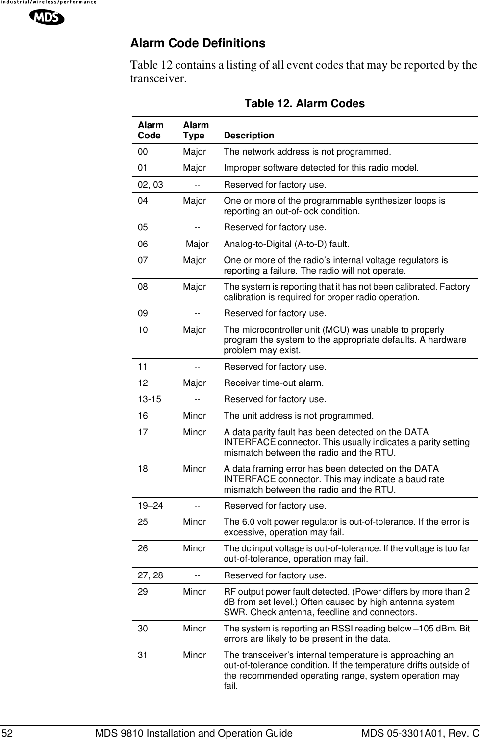
![42 MDS 9810 Installation and Operation Guide MDS 05-3301A01, Rev. CR-M indicates that the transceiver has been programmed to the special remote-master mode (remote radio operating on master frequencies) This is used in repeater-assisted peer-to-peer systems; see Section 2.2, Typical Applications (beginning on Page 3) for details. The R-M mode denotes a remote radio operating on master frequencies. In all other respects, a remote-master behaves the same as a normal remote.All units default to remotes; other modes must be specifically pro-grammed with the MODE command.OWM [xxxxx]The OWM command sets or displays an optional owner’s message, such as the system name. The entry can contain up to 30 characters.OWN [xxxxx]The OWN command sets or displays an optional owner’s name, such as the site name. The entry can contain up to 30 characters.PWR [xx–30]This command displays or sets the desired RF forward output power set-ting of the radio. The PWR command parameter is specified in dBm and can range from 20 to 30 dBm in 1 dBm steps. The default setting is 30 dBm (1 watt). To read the actual (measured) power output of the radio, use the SHOW PWR command.In the USA and Canada, maximum allowable power is governed by limits on Effective Isotropic Radiated Power output (EIRP). The EIRP limit of +36 dBm means that any user with a net antenna gain greater than 6 dBi must decrease the PWR setting accordingly. Section 3.5, How Much Output Power Can be Used? (beginning on Page 13) contains a detailed discussion of this topic.RSSIThis command displays the radio’s Received Signal Strength Indication in dBm (decibels relative to 1 mW). The output can range from –50 dBm to –110 dBm. Command availability and results depend on the mode of operation (master or remote). The closer to 0 dBm, the stronger the signal, thus a reading of –70 dBm is stronger than –80 dBm.For a remote radio, under normal operation, RSSI is based on the average signal strength of the SYNC message received in each of the eight frequency zones. (RSSI is sampled each time a SYNC message is received—every 1.6 seconds.) When using the RSSI reading to align a directional antenna, it is important to make changes slowly so that the RSSI reading will provide meaningful results. It will take several sec-onds to indicate a change in signal level. The radio stays in RSSI mode until is pressed.ENTER](https://usermanual.wiki/GE-MDS/DS-9810.Manual-revision-2/User-Guide-457660-Page-50.png)
![MDS 05-3301A01, Rev. C MDS 9810 Installation and Operation Guide 43For a master radio, under normal operation, entering the RSSI command causes the response NOT AVAILABLE to be returned. This is because a master is normally receiving signals from several remote stations and an RSSI reading would be continually changing. The only exception is when the SETUP command has been asserted. This disables hopping and allows reading a “raw” RSSI signal level in real time from a master or remote radio.NOTE: RSSI Readings are not accurate for incoming signals strongerthan –50 dBm.)RTU [ON/OFF/0-80]This command re-enables or disables the radio’s internal RTU simu-lator, which runs with MDS’ proprietary polling programs (poll.exe and rsim.exe). The internal RTU simulator is available whenever a radio has diagnostics enabled. This command also sets the RTU address that the radio will respond to.The internal RTU can be used for testing system payload data or pseudo bit error rate (BER) testing. It can be helpful in isolating a problem to either the external RTU or the radio.RX [xxxx]This command sets or displays the test receive frequency used in place of hopping whenever the radio is in Setup mode. The test receive fre-quency can be reprogrammed to any value between 927.975 MHz and 902.025 MHz, inclusive. The factory default settings are listed below and have been selected to be non-intrusive to normal operation.RXTOT [NONE, 0–1440]This command sets or displays the amount of time (in minutes) to wait for the next received data packet before issuing a receiver time-out alarm. The default is NONE.SEND [n, -n, +n]The SEND command selects or displays the number of times that a radio will re-transmit data. This command is associated with “robust” or “bul-letproof” operation of the radio and is intended for use in areas with heavy radio interference.Default Receive FrequenciesMaster Remote927.975 MHz 902.025 MHz](https://usermanual.wiki/GE-MDS/DS-9810.Manual-revision-2/User-Guide-457660-Page-51.png)
![MDS 05-3301A01, Rev. C MDS 9810 Installation and Operation Guide 45When the SETUP command is entered, the HHT prompt changes to SETUP>, and:• Hopping is disabled.• Synthesizer frequencies are reset to the test frequencies speci-fied by the TX and RX commands.• The radio can be keyed using the KEY command. DKEY is used to unkey the radio. (If the radio is left in a keyed state it is auto-matically unkeyed after several minutes.)• The RSSI is sampled in a raw, continuous fashion regardless of whether the unit is a master or a remote.Entering Q or QUIT returns the system to normal operation.A timer keeps the Setup mode from accidentally leaving the system dis-abled. After 10 minutes the system behaves as if Q or QUIT had been entered, returning to normal operation.SHOW [PORT, DC, PWR]The SHOW command displays three types of information based on the command variables. These are:•PORT—Displays which connector port (RJ-11 or DB-25) is cur-rently active for diagnostics and control.•DC—Displays DC input/output voltages.•PWR—Displays the actual (measured) RF power output in dBm. Unlike the PWR command, this command shows the actual level being measured, not the programmed RF power setting.SIMPLEX [ON, OFF]The SIMPLEX command sets or displays the radio’s mode of operation (simplex or half-duplex).By default, the system operates in half-duplex mode (SIMPLEX OFF). In this mode, the transmit frequency of the master is the receive frequency of the remote (and vice-versa). The transceiver uses a transmit/receive frequency split of ±1.6 MHz. The offset varies such that both frequen-cies will always fit within the same zone. (A zone is a 3.2 MHz sub-band—see the ZONE DATA command.)When simplex mode is selected (SIMPLEX ON), the master and remotes always transmit and receive on the same frequency. This setting is required for peer-to-peer simplex networks where remotes must be able to communicate with other remotes. A slight increase in end-to-end delay will occur when using this mode.This command is “read-only” at remote radios. (Remotes must be syn-chronized with the master radio to read the simplex status.)](https://usermanual.wiki/GE-MDS/DS-9810.Manual-revision-2/User-Guide-457660-Page-53.png)
![46 MDS 9810 Installation and Operation Guide MDS 05-3301A01, Rev. CSKIP [NONE, 1...8]This command sets or displays which, if any, of the eight 3.2 MHz (128 frequency) zones will be skipped from the radio’s hopping sequence. Skipping zones is one way of dealing with constant interference on one or more frequencies. See Section 3.3 (Page 10) for more information on dealing with interference.Figure 24 shows the frequency range covered by each zone. The com-mand parameter is either the keyword NONE or an undelimited string of up to seven digits where each digit 1...8 represents a corresponding zone to skip. (For zone parameter input, the digits can appear in any order and can be optionally separated by a blank space.) The SKIP command is read-only at remote radios. (Remotes must be synchronized with the master radio to read the skip status.)Figure 24. Frequency Zones for MDS 9810 TransceiverSKIPSYNC [ON/OFF]Selectively suppresses transmission of SYNC messages in skipped zones (see SKIP command above). With SKIPSYNC set to ON, the trans-ceiver will not transmit SYNC messages in skipped frequency zones.This command is only available to transceivers that are set to be a master (MODE M). The default setting for this command is OFF.NOTE: Using SYNCSKIP when many zones are skipped will signifi-cantly lengthen the time it takes a remote to achieve synchro-nization with the master. (This will also manifest itself as veryslow RSSI reading response).SNRThis command displays the signal-to-noise ratio of the received signal expressed in dB. As used in this guide, the definition of signal-to-noise is based upon the signal level following equalization, for valid frames only. (A valid frame is defined as containing no more than one bit error, and belonging to a frame addressed for the receiving radio.) SNR is updated and latched for each valid frame received. A filter in the DSP tempers the effect of any sudden changes in the value.ZONE 1902.200to905.375ZONE 2905.400to908.575ZONE 3908.600to911.775ZONE 4911.800to914.975ZONE 5915.000to918.175ZONE 6918.200to921.375ZONE 7921.400to924.575ZONE 8924.600to927.775](https://usermanual.wiki/GE-MDS/DS-9810.Manual-revision-2/User-Guide-457660-Page-54.png)
![MDS 05-3301A01, Rev. C MDS 9810 Installation and Operation Guide 47SNR output ranges from 10 dB to 33 dB. A value of 10 dB represents little or no signal. A value of 24 dB represents a very strong signal. For remote radios, a value of 0 is reserved to mean “no signal”; it is dis-played whenever a remote is not in synchronization with the master sta-tion.When the SNR command is used, it causes the DIAG(NOSTIC) port to enter an update mode, and it will provide an updated signal-to-noise ratio every 1.6 seconds. It stays in this mode until the key is pressed.SREVThis command displays the software version currently loaded into the transceiver.A display of 06-3111A01, 3.5.1 is an example of the software version iden-tifier.STATThis command is used to check alarm status. If no alarms exist, the mes-sage NO ALARMS PRESENT appears at the top of the HHT display.If an alarm does exist, a two-digit event code (00–31) is displayed and the event is identified as a “major” or “minor” alarm. A brief description of the event is also given.If more than one alarm exists, the word MORE appears at the bottom of the screen and additional alarms are viewed by pressing the key. Detailed descriptions of the alarm codes are provided in Table 12 on Page 52.TDD [ON/OFF]The TDD command selects or displays whether or not the DATA INTER-FACE port is operating in time division duplex (sometimes called “sim-ulated full-duplex”) mode. This command is “read-only” at remote radios.The x810 Transceiver is physically a half-duplex device. The radio can never actually transmit and receive RF data at the same time. However, TDD mode enables the radio to simulate full-duplex at the data port, by designating alternate hops as transmit or receive hops, and buffering (storing) data when transmission is not permitted. Default operation is TDD OFF.ENTERENTER](https://usermanual.wiki/GE-MDS/DS-9810.Manual-revision-2/User-Guide-457660-Page-55.png)
![48 MDS 9810 Installation and Operation Guide MDS 05-3301A01, Rev. CNote that when TDD is enabled (TDD ON), there is a significant impact on both data throughput and latency. Data throughput is roughly cut in half. Worst case data latency is increased by two hoptimes. The effect in seamless mode (BUFF ON) is even more pronounced, as shown in Table 10.TEMPThis command displays the internal temperature of the transceiver in degrees Celsius. (Note that the radio is specified to operate in an envi-ronment between –30 C° and +60 C°). This internal reading may be higher than the outside temperature by several degrees.TX [xxxx]This command sets or displays the test transmit frequency used in place of hopping whenever the radio is in Setup mode. The test transmit fre-quency can be reprogrammed to any value between 902.025 MHz and 927.975 MHz, inclusive. The factory default settings are listed below and have been selected to be non-intrusive to normal system operation.UNIT [10000–65000]This command sets the unit addressing for network-wide diagnostics. The unit address is factory programmed to the last four digits of the serial number. If re-programmed in the field, the entry must consist of five digits between 10000 and 65000.Table 10. Hoptime Setting vs. Delay (BUFF ON—”Seamless Mode”)HOP TIME MINIMUM DELAY MAXIMUM DELAYXSHORT 33 ms 66 msec16 39 ms 78 ms20 43 ms 86 ms25 48 ms 96 ms32 55 ms 110 msSHORT 63 ms 126 msecNORMAL 103 ms 206 msecLONG 183 ms 366 msecDefault Transmit Frequencies Master Remote902.025 MHz 927.975 MHz](https://usermanual.wiki/GE-MDS/DS-9810.Manual-revision-2/User-Guide-457660-Page-56.png)
![MDS 05-3301A01, Rev. C MDS 9810 Installation and Operation Guide 49ZONE DATAThe transceiver divides its frequency operating spectrum into eight con-tiguous 3.2 MHz zones. (These are the same zones referenced by the SKIP command described earlier.) Data frame statistics are maintained for each zone to indicate the transmission quality through the network. This information is useful for identifying zones where significant inter-ference exists.Zone quality information can be accessed using the ZONE DATA com-mand on a connected HHT. For each zone (1–8), it shows you the number of data frames sent, the number received, and the number received with errors. If an excessive number of errors are seen in one or more frequency zones, it may indicate interference, and you should con-sider “skipping” those zones using the SKIP command.The ZONE DATA command displays its information on four lines as shown in Figure 25. If the display seems to “roll off” the screen, verify that your HHT is set for an 80 character screen size. See Section 6.2, Hand-Held Terminal Setup (beginning on Page 29).Invisible place holderFigure 25. HHT Display for ZONE DATA CommandIf ZONE DATA alone is entered, the information for Zone 1 is displayed first. Successive zones can be viewed by pressing the ENTER key, or by entering the zone number of your choice (1...8) at the NEXT ZONE?> prompt.It is also possible to go directly to a specific zone by entering ZONE DATA [1...8], where the number entered equals the desired zone. Data for the specified zone is displayed and then control returns to the command prompt.Entering Q or QUIT causes the program to exit and return to the command prompt.TOTAL SENTTOTAL RECEIVEDTOTAL REC'D WITH ERRORSZONE #DATA FRAME STATISTICS](https://usermanual.wiki/GE-MDS/DS-9810.Manual-revision-2/User-Guide-457660-Page-57.png)
![54 MDS 9810 Installation and Operation Guide MDS 05-3301A01, Rev. CA complete explanation of remote diagnostics can be found in MDS’ Network-Wide Diagnostics System Handbook (MDS P/N 05-3467A01).1. Program one radio in the network as the root radio by entering the DTYPE ROOT command at the radio.2. At the root radio, use the DLINK ON and DLINK [baud rate] commands to configure the diagnostic link protocol on the RJ-11 port.3. Program all other radios in the network as nodes by entering the DTYPE NODE command at each radio.4. Use the DLINK ON and DLINK [baud rate] commands to configure the diagnostic link protocol on the RJ-11 port of each node radio.5. Connect same-site radios using a null-modem cable at the radios’ diagnostic ports.6. Connect a PC on which MDS InSite software is installed to the root radio, or to one of the nodes, at the radio’s diagnostic port. (This PC may be the PC being used to collect payload data, as shown in Figure 30.)To connect a PC to the radio’s DIAG. port, an RJ-11 to DB-9 adapter (MDS P/N 03-3246A01) is required. If desired, an adapter cable may be constructed from scratch, using the information shown in Figure 27.Invisible place holderFigure 27. RJ-11 to DB-9 Adapter CableTable 13. Network-Wide Diagnostics Radio Setup CommandsCOMMAND DESCRIPTION NETWORK-WIDEDIAGNOSTICSCONFIGURATIONDLINK [xxxxx] Details Page 55 Set baud rate of diagnostics linkDTYPE [NODE/ROOT/GATE/PEER] Details Page 55Set radio’s operational characteristics for network-wide diagnosticsRXDTXDGND235DB-9 FEMALE(TO COMPUTER)TXDRXDGND456RJ-11 PLUG(TO RADIO)RJ-11 PIN LAYOUT16](https://usermanual.wiki/GE-MDS/DS-9810.Manual-revision-2/User-Guide-457660-Page-62.png)
![MDS 05-3301A01, Rev. C MDS 9810 Installation and Operation Guide 557. Launch the MDS InSite application at the PC. (Refer to the InSite user’s manual for details.)DLINK [xxxxx]DLINK followed by the baud rate sets the baud rate (bps) of the diagnos-tics link. The following DLINK baud rates selections are allowed:• 1200• 2400• 4800• 9600• 19200 (default setting)Example: DLINK 4800 sets the RJ-11 DIAG port to operate at 4800 bps. The default is DLINK 19200 and DLINK ON.NOTE: The same baud rate must be entered into the InSite EquipmentList’s BAUD field.DTYPE [NODE/ROOT/GATE/PEER]The DTYPE command specifies the radio’s operational characteristics for network-wide diagnostics. There are four possible types of nodes in a network-wide diagnostics system.The common types are:•NODE–The most common setting, and the default. This is the basic system radio device-type. Typically, the radio network is comprised of nodes and one root. Intrusive diagnostics can orig-inate from any node. However, non-intrusive diagnostics can not be facilitated through a node.•ROOT–Always one, and only one, per network. The root is the focal point of network-wide diagnostics information. Intrusive diagnostics can originate from any radio, including the root. However, the root is the only radio enabling non-intrusive diag-nostics.The default radio device-type is NODE. Less used are:•GATE•PEERThese node types are needed for repeater sub-networks and simplex sub-networks where simplex frequencies are used. See the Net-work-Wide Diagnostics System Handbook for an explanation of these node types.](https://usermanual.wiki/GE-MDS/DS-9810.Manual-revision-2/User-Guide-457660-Page-63.png)