GE MDS DS-5800-2 MDS 5800 II Digital Radio Transceiver User Manual MK MAN 01
GE MDS LLC MDS 5800 II Digital Radio Transceiver MK MAN 01
UserManual.wiki
>
GE MDS
>
DS-5800-2 User Manual
>
manual
Contents
1.
Manual
2.
manual
manual
Navigation menu
Upload a User Manual
Namespaces
Wiki Guide
HTML
PDF
Info
Views
User Manual
Discussion / Help
Navigation

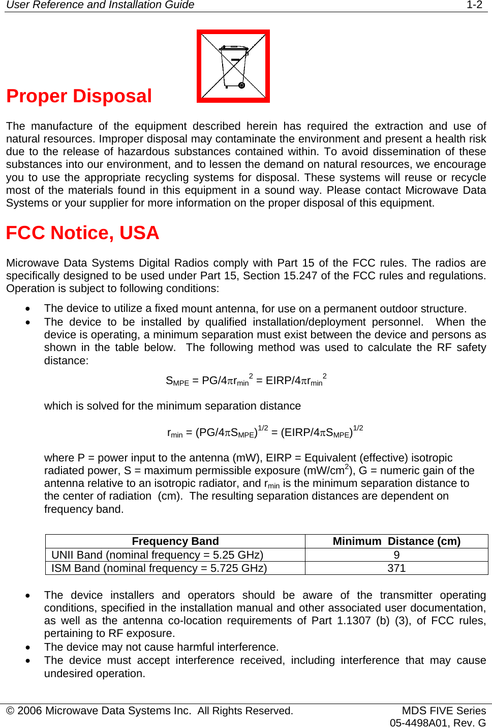
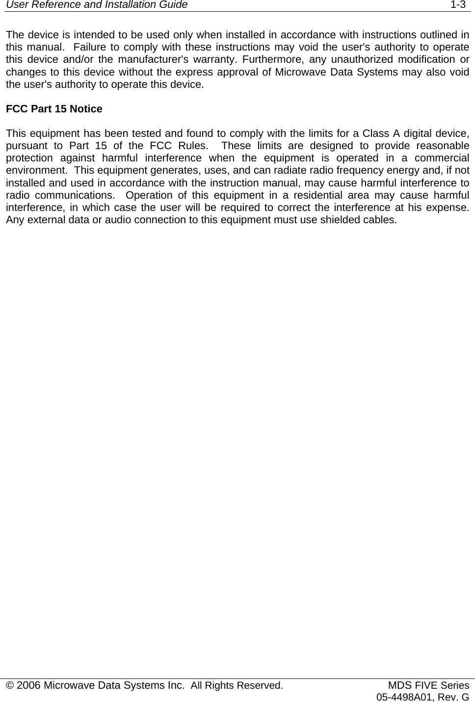
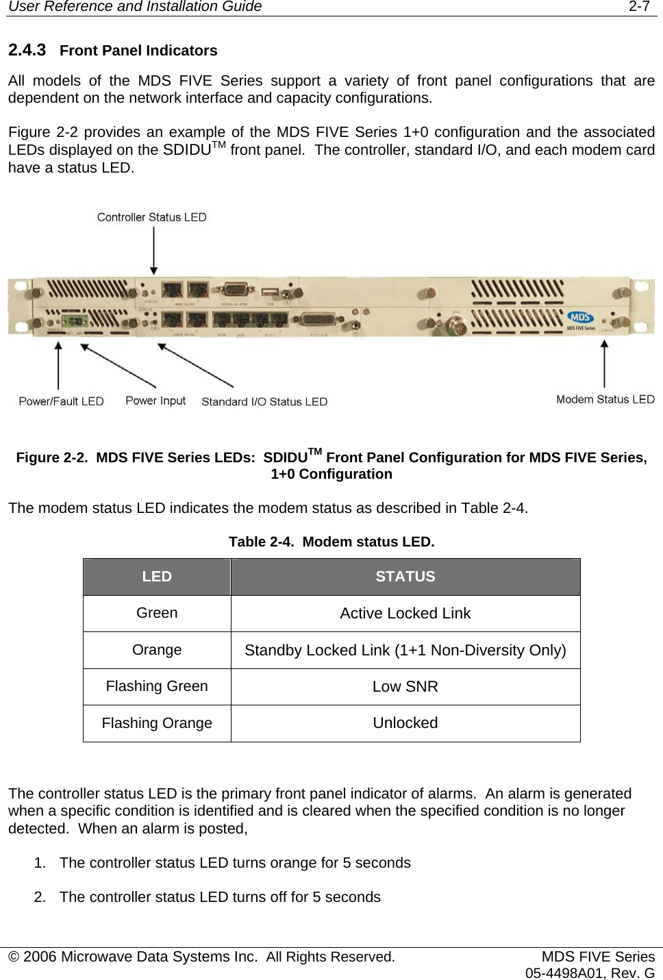
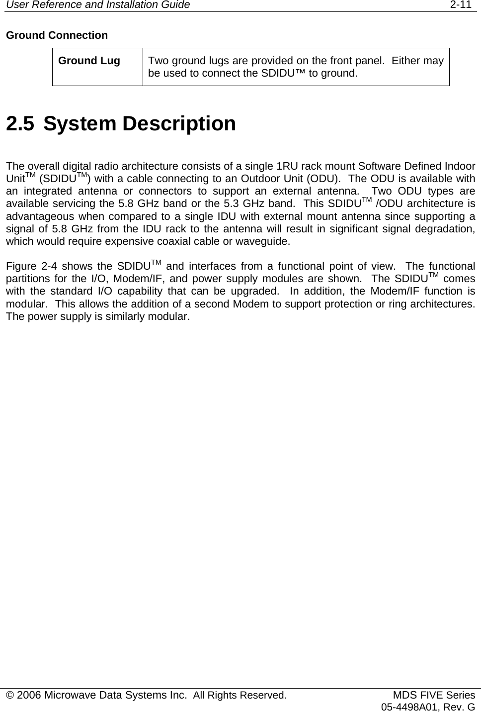
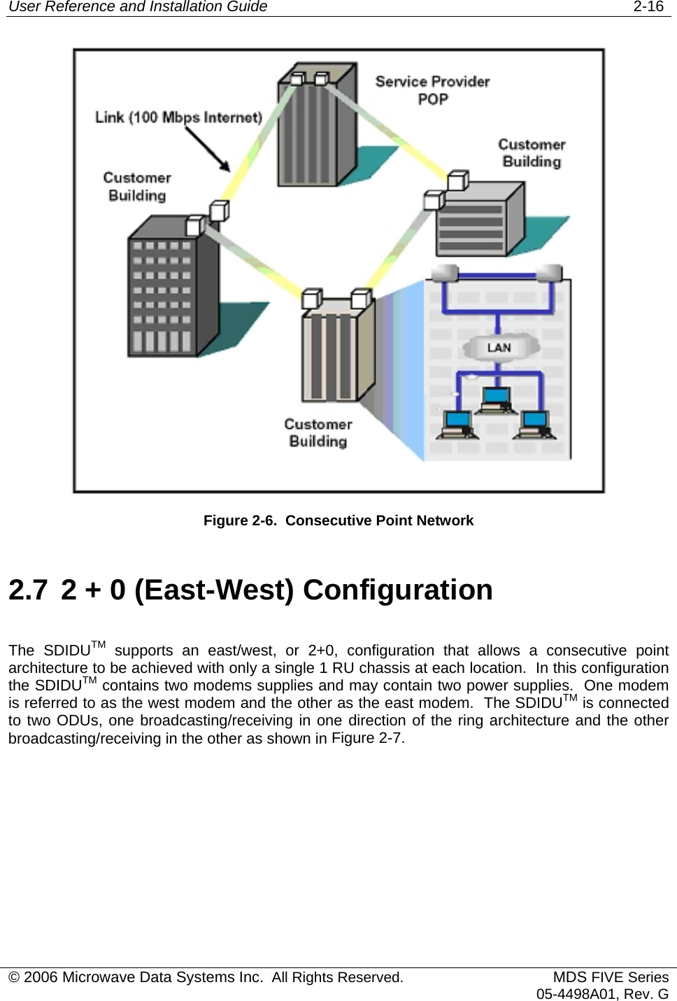
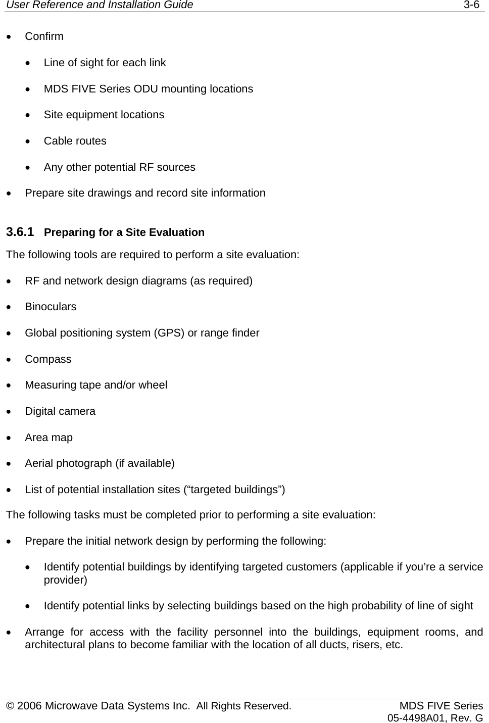
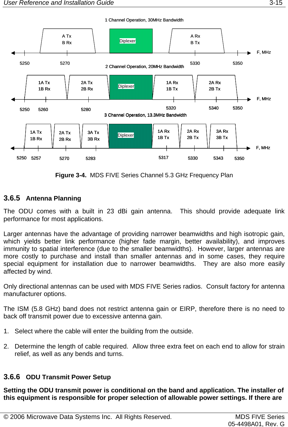
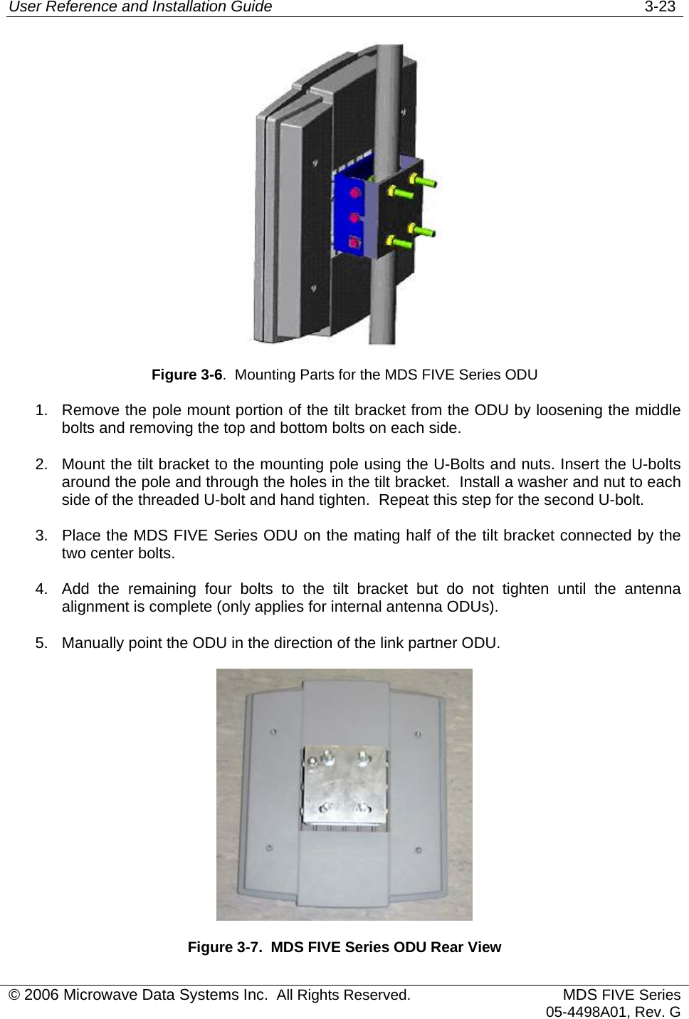
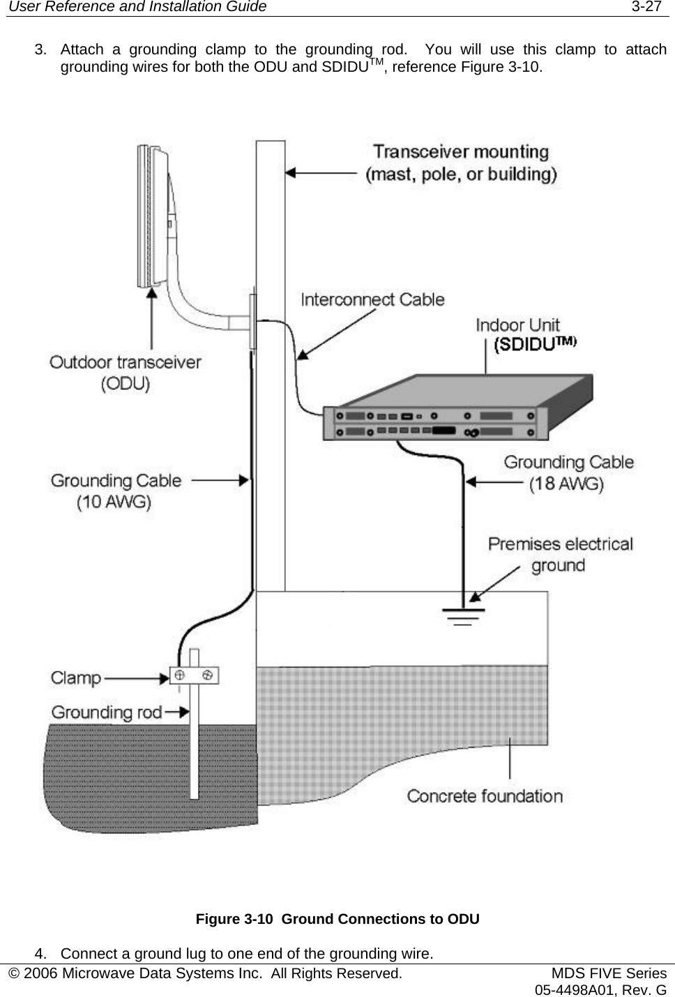
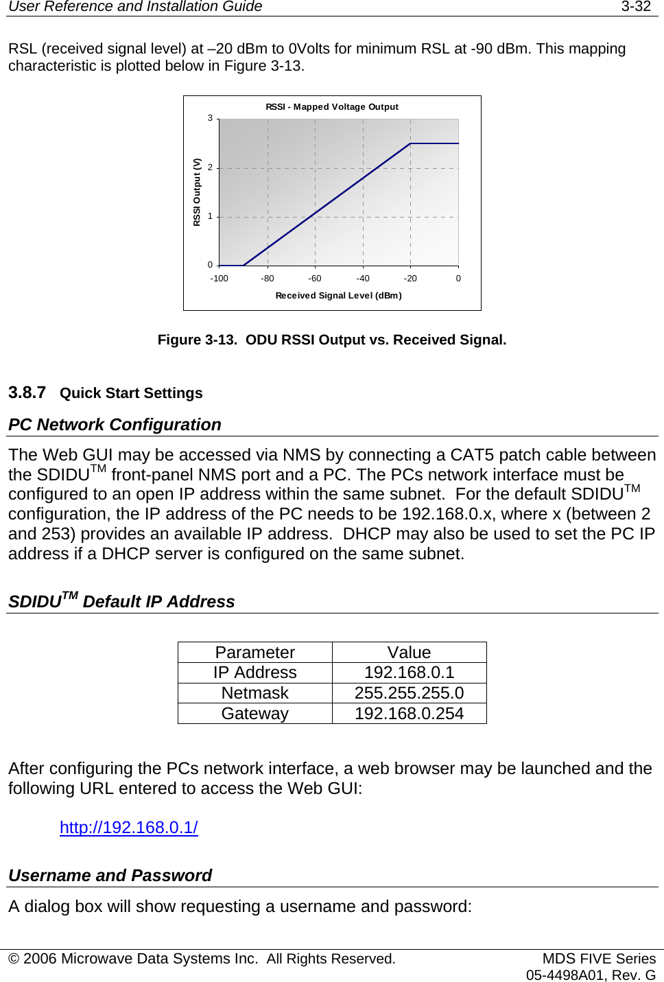
![User Reference and Installation Guide 3-10 MDS FIVE series Link Planner: 5.3GHz AvailabilityParameterOperating Frequency (MHz)Transmit Antenna Gain (dBi)Transmitter Output Power (dBm)Receive Antenna Gain (dBi)Link Distance 3.93 milesFresnel Clearance Ratio1,2Climate FactorTerrain FactorMDS FIVE series Mode5.3GHz Band Modem Data Rate (Mbps)Channel Bandwidth (MHz)Receiver Sensitivity3 (dBm)Link Fade Margin (dB) ODU RSSI (dBm) Availability (%)5.3G-25FE1 31.112E+6 30.0 -83 12 -71 99.99875.3G-25FE2 31.112E+6 20.0 -82 11 -71 99.99845.3G-25FE3 31.112E+6 13.3 -82 11 -71 99.99845.3G-50FE1 56.733E+6 30.0 -80 9 -71 99.99755.3G-50FE2 56.733E+6 20.0 -77 6 -71 99.99505.3G-50FE3 56.733E+6 13.3 -72 1 -71 99.98455.3G-100FE1 107.797E+6 30.0 -73 2 -71 99.98765.3G-16E1-2 36.918E+6 20.0 -82 11 -71 99.99845.3G-16T1-2 28.655E+6 20.0 -84 13 -71 99.99905.3G-16E1-3 36.918E+6 13.3 -82 11 -71 99.99845.3G-16T1-3 28.655E+6 13.3 -84 13 -71 99.9990Note1: FCC's definition; negative clearance indicates no optical LOS; range is [-1,…,0.6]; 0.6 is radio LOS condition.Note2: Accounting for single knife-edge diffraction loss only.Note3: BER<<1e-6.Note4: Listed data rates inlcudes 2 E1 Wayside channels, except for 16E1/T1 modes.(miles)99.9%99.99%99.999%5.3G-25FE1 QPSK 3/4 -83 9535.3G-25FE2 16QAM 3/4 -82 9535.3G-25FE3 16QAM 3/4 -82 9535.3G-50FE1 16QAM 3/4 -80 8535.3G-50FE2 32QAM 4/5 -77 7425.3G-50FE3 64QAM 11/12 -725325.3G-100FE1 32QAM 9/10 -735325.3G-16E1-2 16QAM 3/4 -82 9535.3G-16T1-2 16QAM 3/4 -84 9635.3G-16E1-3 16QAM 7/8 -82 9535.3G-16T1-3 16QAM 7/8 -84 96323for Various AvailabilityMax DistanceValue5300236MDS FIVE series Mode Modulation and Code RateReceiver Sensitivity3 (dBm)0.600.251 © 2006 Microwave Data Systems Inc. All Rights Reserved. MDS FIVE Series05-4498A01, Rev. G](https://usermanual.wiki/GE-MDS/DS-5800-2.manual/User-Guide-766081-Page-44.png)