Futaba T4GRS-24G Radio Control User Manual Part 3
Futaba Corporation Radio Control Part 3
UserManual.wiki
>
Futaba
>
T4GRS-24G User Manual
>
User Manual Part 3
Contents
1.
User Manual Part 1
2.
User Manual Part 2
3.
User Manual Part 3
User Manual Part 3
Navigation menu
Upload a User Manual
Namespaces
Wiki Guide
HTML
PDF
Info
Views
User Manual
Discussion / Help
Navigation
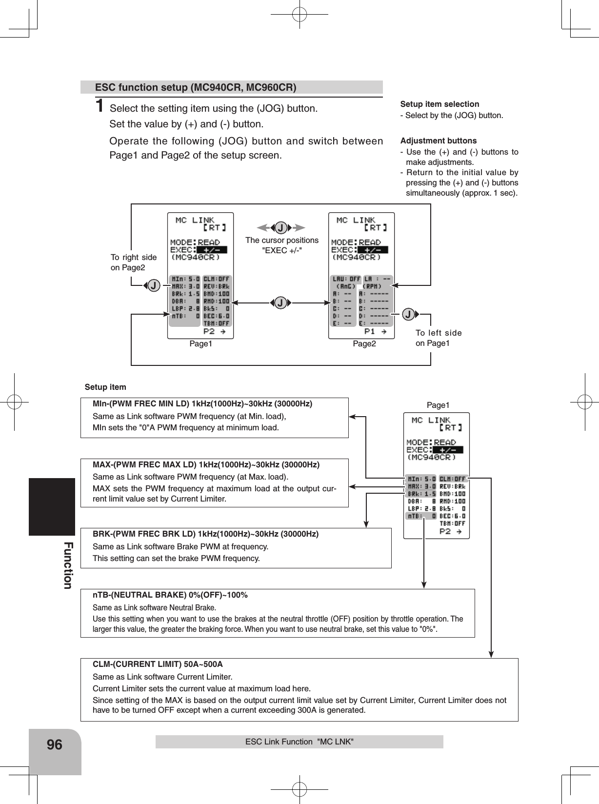
![99FunctionLAU-(LEAD ANGLE USE) ON /OFFSame as Link software Lead Angle UseThis function is effective when TBM (Turbo Mode) is LEV1 or LEV2 and sets whether or not lead angle is used. This setting has priority over the TURBO MODE setting. When using in races in which the lead angle func-tion is inhibited by the ESC set this function to OFF.OFF : Lead angle function not used.ON : Lead angle usedLA-(LEAD ANGLE) 0~59 degSame as Link software Lead AngleWhen LAU (LEAD ANGLE USE) is turned on the motor lead angle can be set at the MC960CR. The lead angle can be set up to 59 degrees in 1 degree increments.A,B,C,D,E BA-(A,B,C,D,E BOOST ANGLE) 0~59 degSame as Link software Boost AngleA,B,C,D,E RPM-(A,B,C,D,E BOOST ANGLE RPM) 0~99990 rpmSame as Link software Boost Angle rpmWhen LAU (LEAD ANGLE USE) is turned on the lead angle versus motor speed of the 5 points A to E can be set. The lead angle can be set up to 59 degrees in 1 degree increments.Note: Do not read to the T4GRS an MC940/960CR whose speed was set to over 99990rpm by Link software side Boost Angle rpm setting.Page2When using in races in which the lead angle setting function is inhibited by the ESC, set LAU (LEAD ANGLE USE) to OFF. The LAU setting has priority over TBM-(TURBO MODE). If LAU is set to "OFF", the lead angle setting function can be turned off even if TBM is set to "LV1" or "LV2".The MC940,960CR shows that the lead angle setting function is OFF ("0" timing) by flashing an LED.The LA-(LEAD ANGLE) and A, B, C, D, E BA- (A, B, C, D, E BOOST ANGLE) relationship is shown on the graphs below. Graph [A] shows the relationship when the same value is set at points A, B, C, D, E BA-(A, B, C, D, E BOOST ANGLE) of [A] and [B] and the LA-(LEAD ANGLE) was set to "0" and graph [B] shows the relationship when a value other than "0" was set at LA-(LEAD ANGLE).As shown in the graphs, [B] is added to the A, B, C, D, E BA-(A, B, C, D, E BOOST ANGLE) set lead an-gle and [A] is added to the LA-(LEAD ANGLE) set lead angle. For example, if "3" is set at ABA and LA of [B] is set to "2", the actual ABA becomes 3+2=5 (deg). Since LA of [A] is "0", the actual ABA also becomes 3+0=3 (deg).RPM(A) RPM(B) RPM(C) RPM(D) RPM(E)AnG(A)AnG(B)AnG(C)AnG(D)AnG(E)RPM(A) RPM(B) RPM(C) RPM(D) RPM(E)AnG(A)LAAnG(B)AnG(C)AnG(D)AnG(E)B (LA >"0")A (LA ="0") Lead Angle(deg) Lead Angle(deg)rpmrpmESC Link Function "MC LNK"](https://usermanual.wiki/Futaba/T4GRS-24G.User-Manual-Part-3/User-Guide-2495376-Page-14.png)
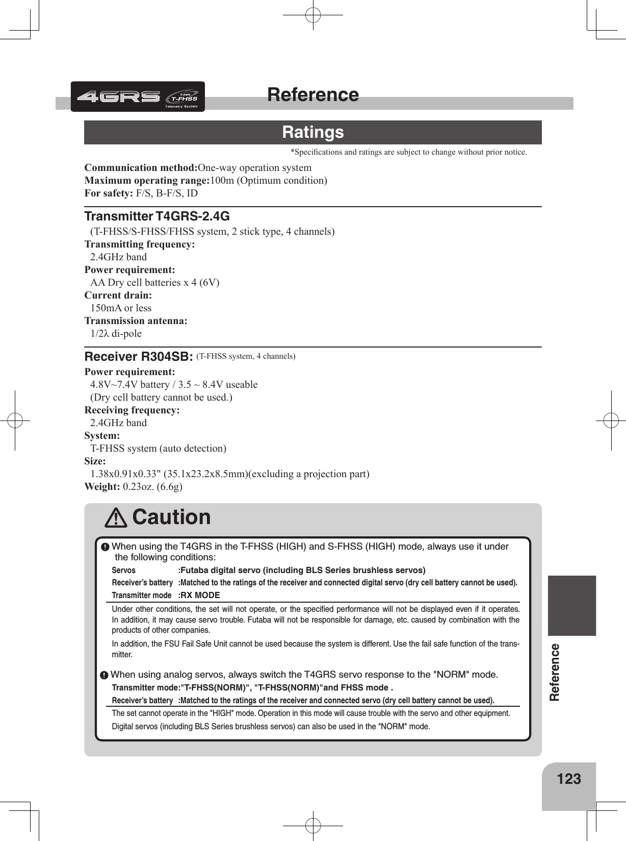
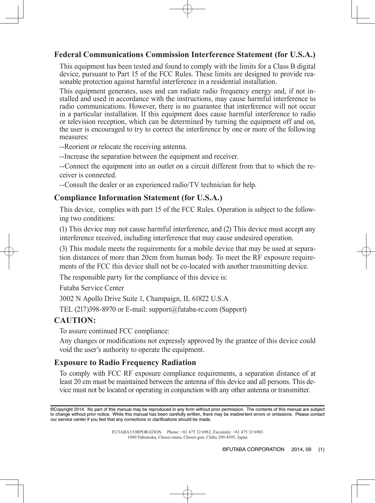
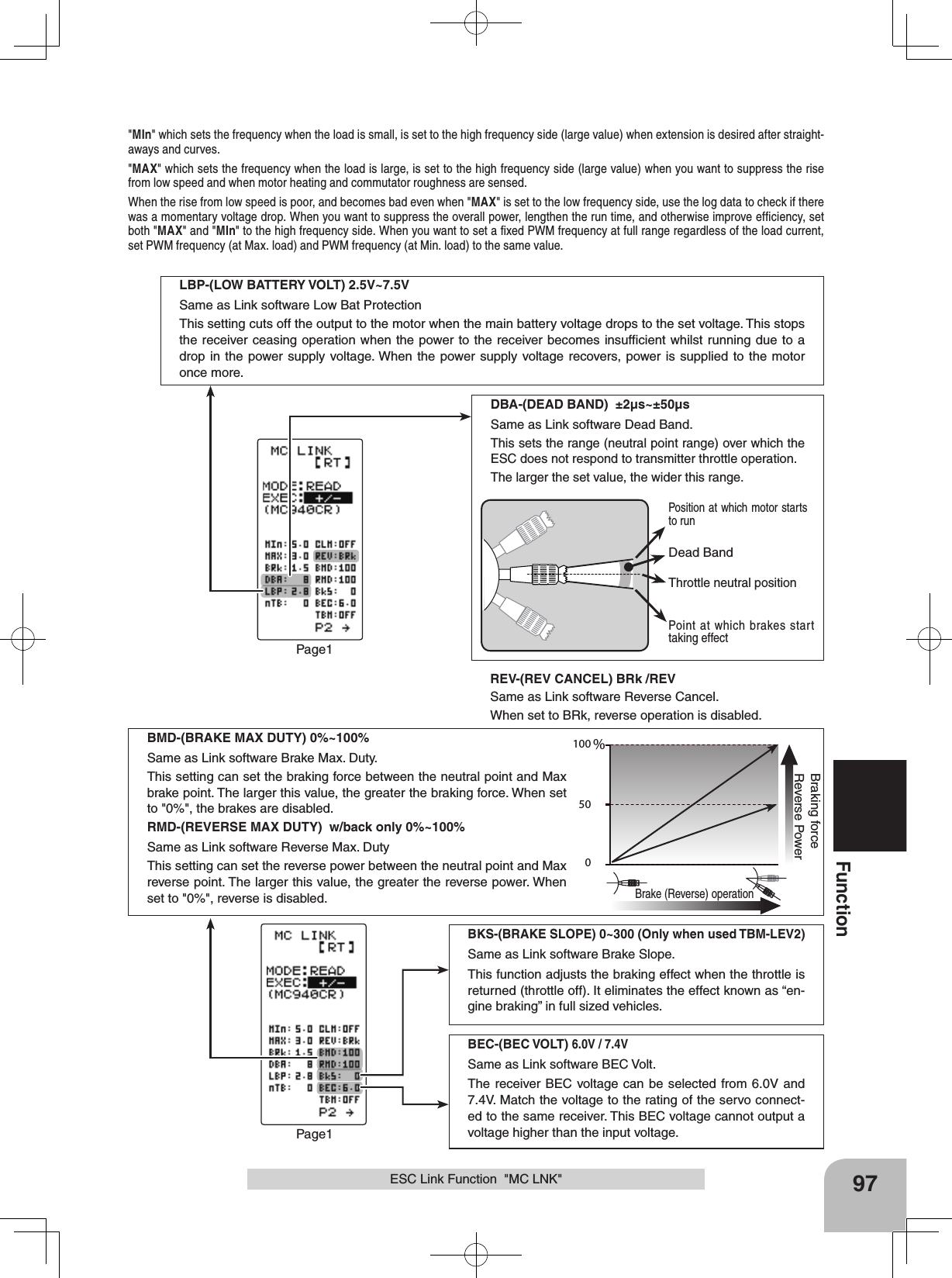
![Display "SYSTEM" screen by the following method:PressPressCONTRALHT-TMBK-LHTSYSTEMLHT-PWBATT DRY4OPE-TMBUZZERMENUTH-STKDISP0ALL10s1565OFFTLMTRENG5 5 RT PressPressSelect "SYSTEM"(HOME screen) (MENU 1 screen) (SYSTEM screen)(MENU 2 screen)Contrast (CONTRA) -10~0~+10 Initial value: 0CONTRALHT-TMBK-LHTSYSTEM[ RT ]LHT-PWBATT DRY4OPE-TMBUZZERMENUTH-STKDISPALL10s1565OFFTLMTRENG5 50109FunctionSystem Functions "SYSTEM"System Functions "SYSTEM"The graphic liquid crystal screen display mode, buzzer sound and menu character mode, etc. can be set. - "CONTRA"---Liquid crystal screen contrast adjustment (20 steps) - "BK-LHT"---Liquid crystal screen backlighting display mode setup (OFF, ON at button operation, normally ON) - "LHT-TM"---Setting of ON time (1~30 secs) when [ON at button operation] was selected above. - "LHT-PM"---Liquid crystal screen backlighting brightness adjustment (30 steps) - "BATT"---Battery type setting (LiFe2/NiMH5/DRY4) The T4GRS can use an optional rechargeable battery. However, the battery alarm setting is dif-ferent from that of the dry cell battery (alkaline battery recommended). Therefore, always set the battery type to match the power source used. If used with the incorrect setting, the normal low battery alarm function will not work and the sys-tem may stop before a battery alarm is generated. The usage time may also become extremely short. - "BUZZER"---Buzzer sound tone adjustment (OFF, 100 steps) - "OPE-TM"---Alarm Setting if Tx is left switched ON (OFF, 10 m) - "MENU"---Item which displays the basic menu screen in katakana characters for Japanese use.- “TH-STK”---This is used, when the neutral adjuster of throttle stick is changed, or when it is changed into ratchet.(5:5, 7:3, F10) - "DISP"---HOME screen display mode setting (Telemetry data, Timer, Users name)1(Setting of each item)(Adjusting the liquid crystal contrast)Select the setting item "CONTRA" using the (JOG) button, and use the (+) and (-) buttons to adjust the screen contrast.- Adjust to an easy-to-see contrast.When completed, return to the MENU2 screen by pressing the (JOG) button.System function setup Adjustment buttons- Use the (+) and (-) buttons to make adjustments.- Press the (+) and (-) buttons si-multaneously (approx. 1 sec) to return to the initial value.](https://usermanual.wiki/Futaba/T4GRS-24G.User-Manual-Part-3/User-Guide-2495376-Page-24.png)
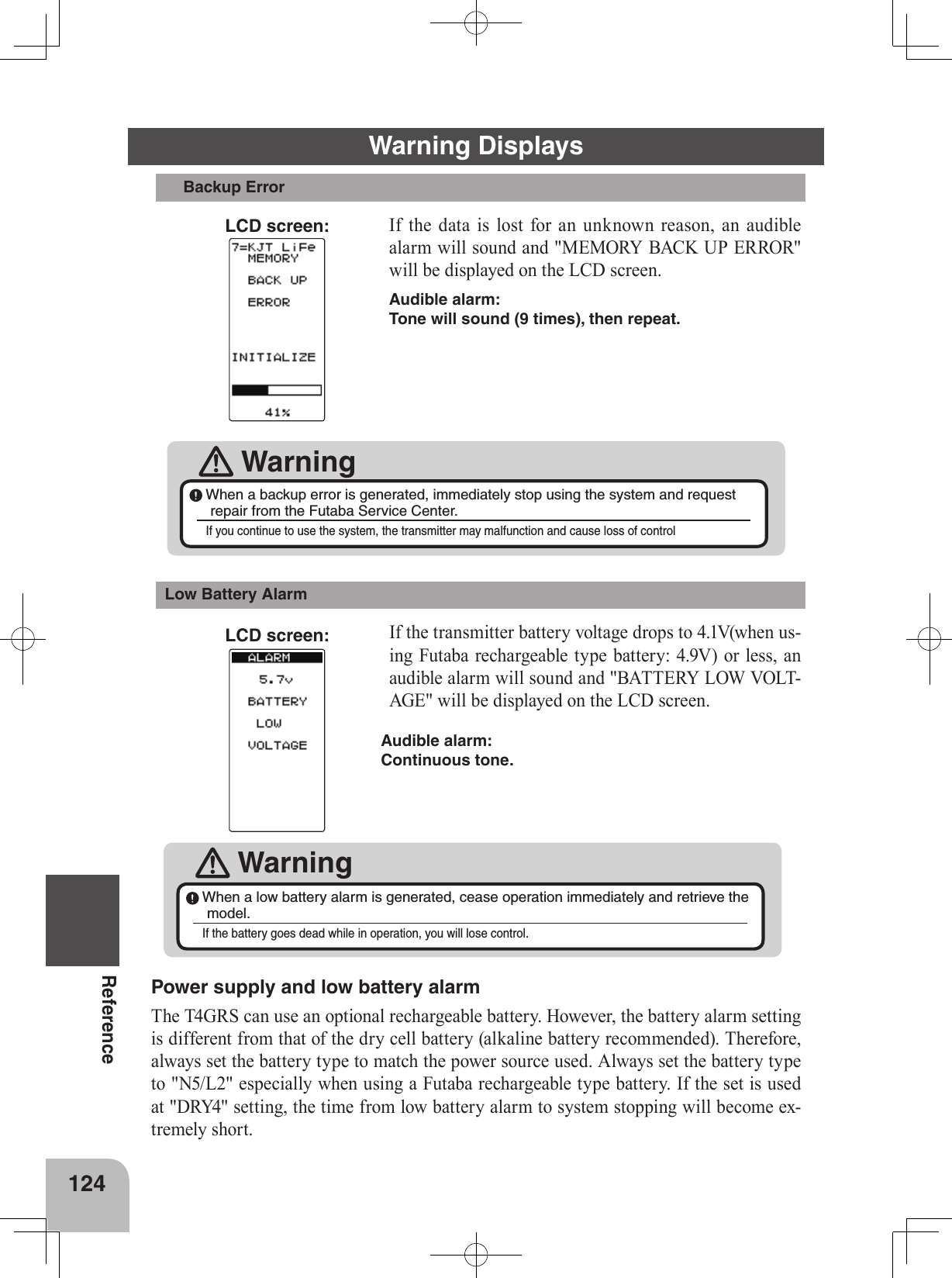
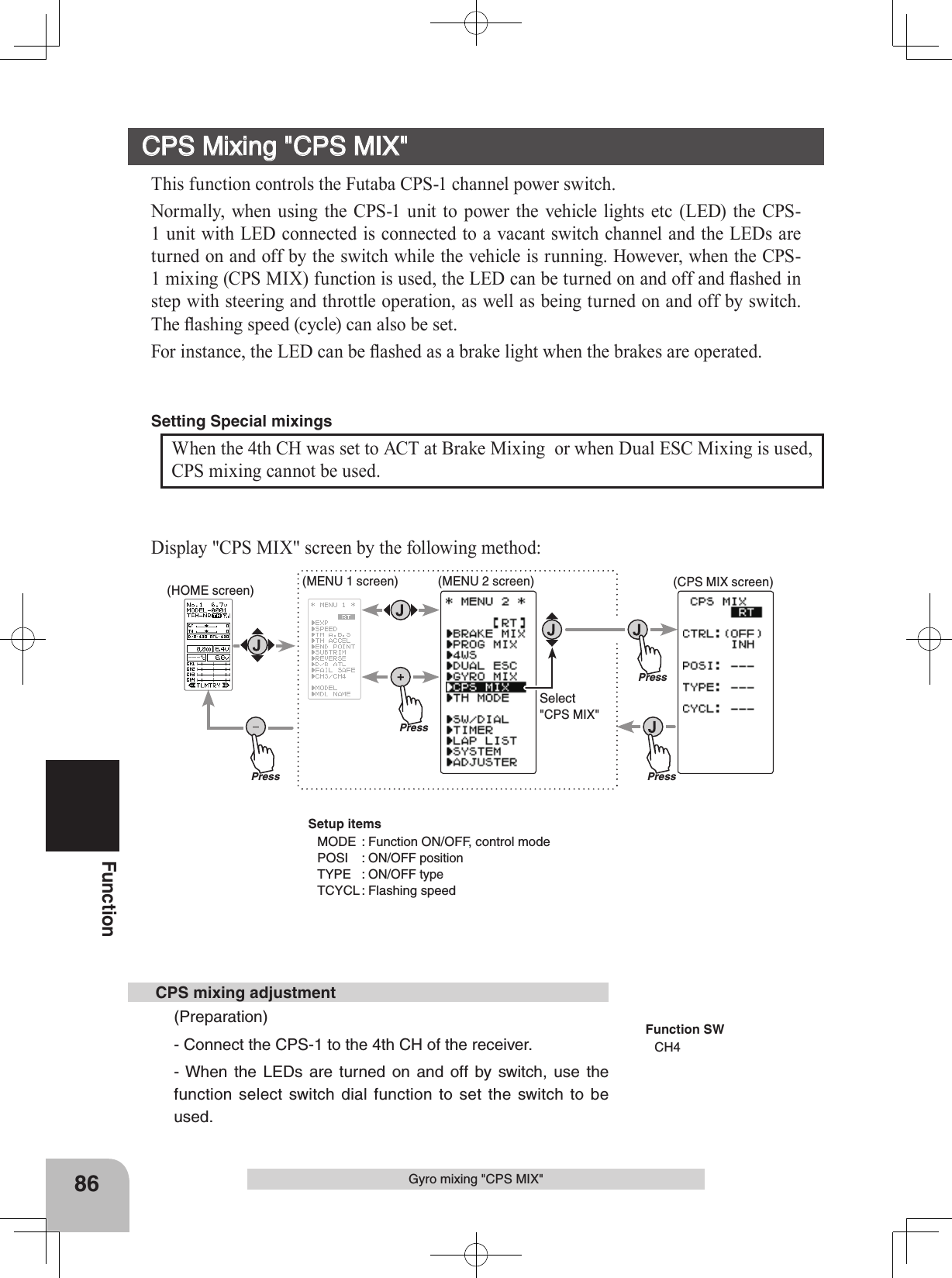
![Backlight mode (BK-LHT) KEY, ALL, OFFBacklighting time (LHT-TM) 1~30 Initial value: 10Backlighting brightness (LHT-PW) 1~30 Initial value: 15CONTRALHT-TMBK-LHTSYSTEM[ RT ]LHT-PWBATT DRY4OPE-TMBUZZERMENUTH-STKDISP1565OFFTLMTRENG5 50ALL10sCONTRALHT-TMBK-LHTSYSTEM[ RT ]LHT-PWBATT DRY4OPE-TMBUZZERMENUTH-STKDISP10s1565OFFTLMTRENG5 50ALLCONTRALHT-TMBK-LHTSYSTEM[ RT ]LHT-PWBATT DRY4OPE-TMBUZZERMENUTH-STKDISP65OFFTLMTRENG5 50ALL10s15Battery Type (BATT) LiFe2, DRY4, NiMH5CONTRALHT-TMBK-LHTSYSTEM[ RT ]LHT-PWBATTOPE-TMBUZZERMENUTH-STKDISP65OFFTLMTRENG5 50ALL10s15DRY4110FunctionSystem function setup(Setting the liquid crystal backlighting mode)Select the setting item "BK-LHT" using the (JOG) button, and select the mode by pressing the (+) or (-) button."KEY" :Fixed time backlighting ON after button operated."ALL" :Backlighting always ON"OFF" :Backlighting OFFWhen completed, return to the MENU2 screen by pressing the (JOG) button.(Setting liquid crystal backlighting time)Select the setting item "LHT-TM" using the (JOG) button, and use the (+) and (-) buttons to set the ON time.- When "KEY" is set at the preceding item, this ON time be-comes effective.When completed, return to the MENU2 screen by pressing the (JOG) button.(Setting liquid crystal backlighting brightness)Select the setting item "LHT-PW" using the (JOG) button, and use the (+) and (-) buttons to set the ON time.-If too set too bright, the battery will quickly be flattened.When completed, return to the MENU2 screen by pressing the (JOG) button.(Setting the battery type)Select the setting item "BATT" using the (JOG) button, and select the mode by pressing the (+) or (-) button. When changing the battery type, press the (JOG) button after thorough-ly checking that the correct battery type has been entered. An electronic beeping sound is generated and the setting is changed.Note: If the battery type is changed to the wrong setting, the low battery alarm will be generated immediately after the change and operation will become impossible.When the low battery alarm was generated, turn off the power and replace the bat-tery with a fully charged battery or a new dry cell battery and then reset the battery type. System Functions "SYSTEM"](https://usermanual.wiki/Futaba/T4GRS-24G.User-Manual-Part-3/User-Guide-2495376-Page-25.png)
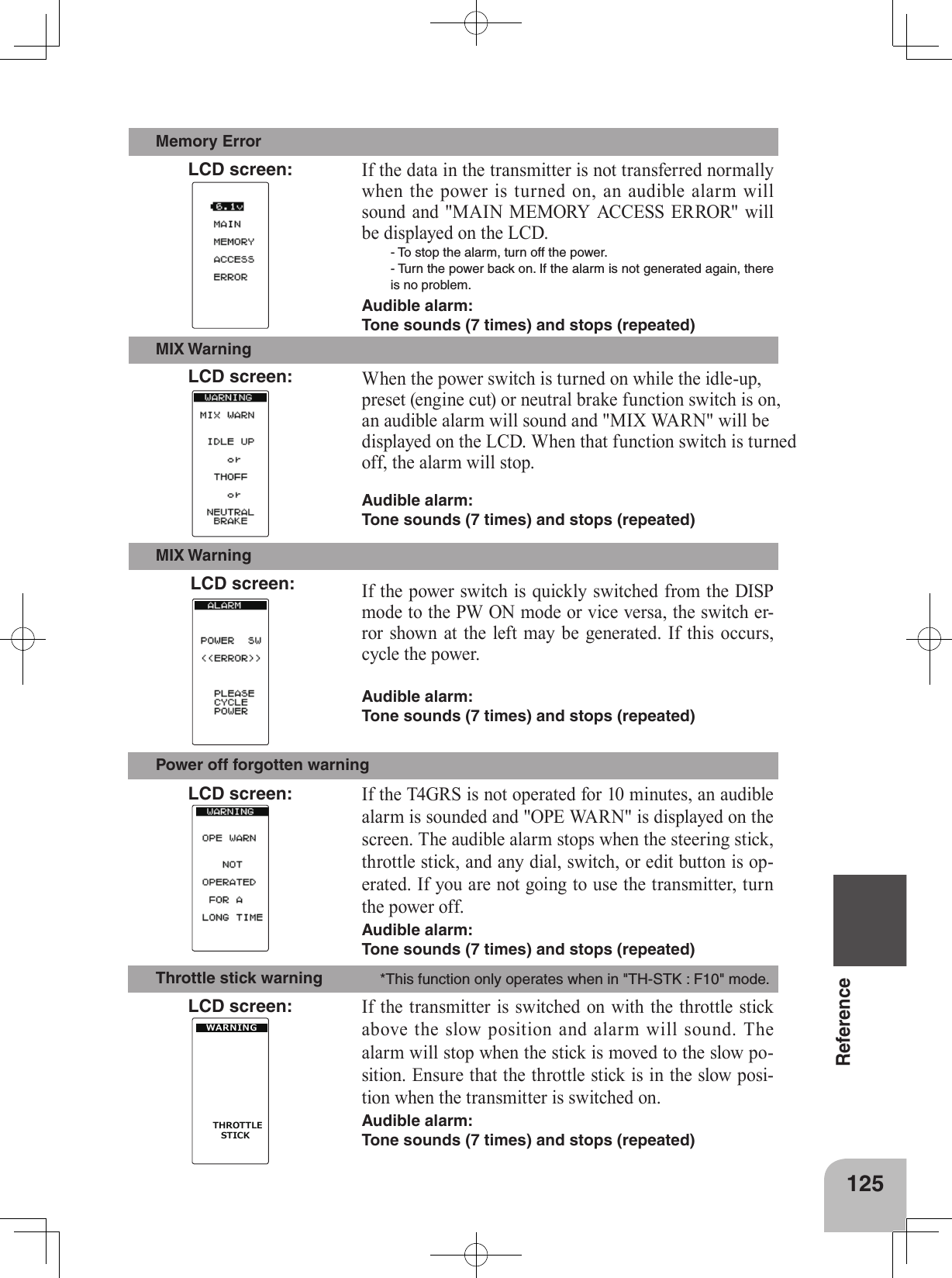
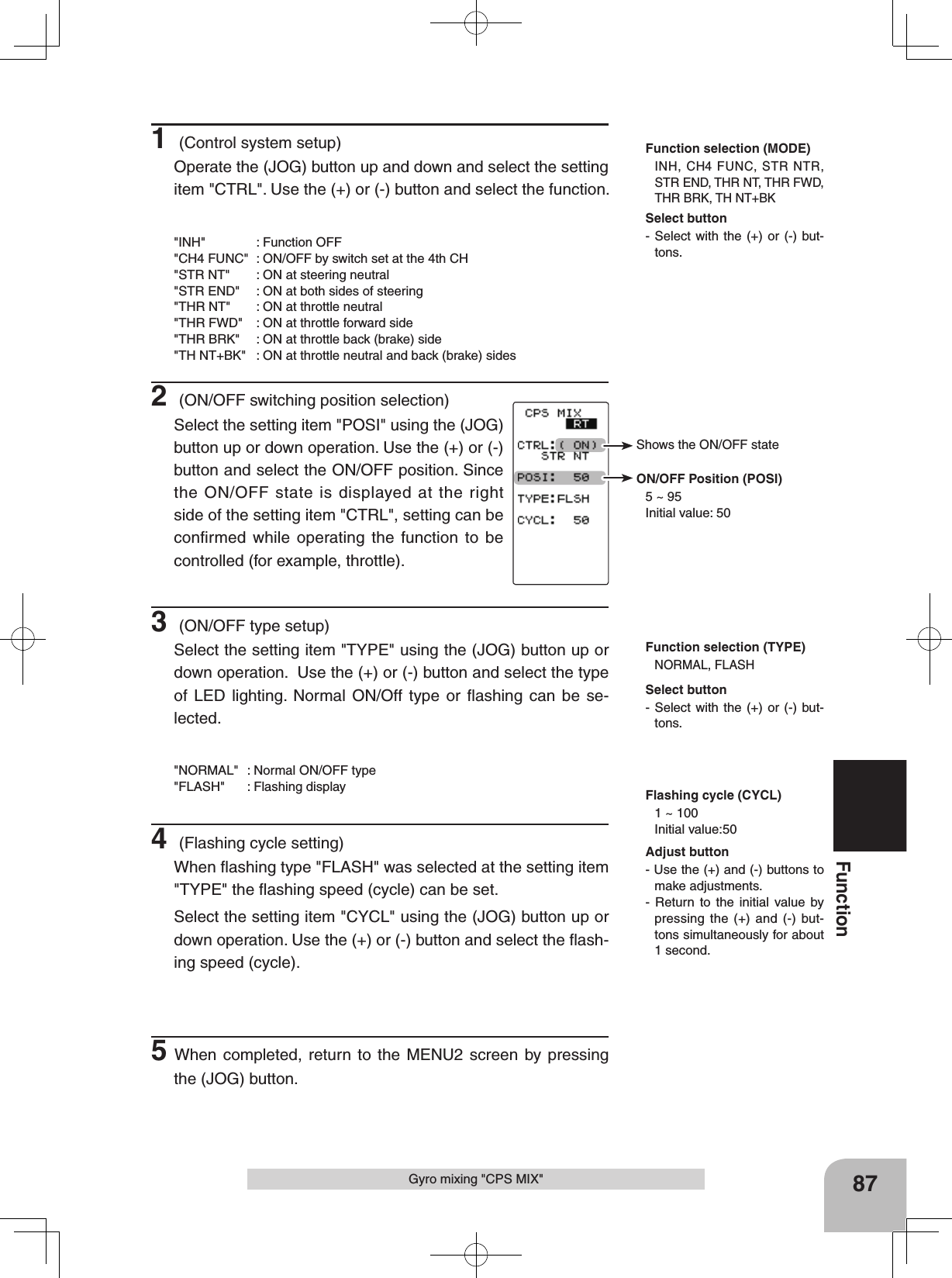
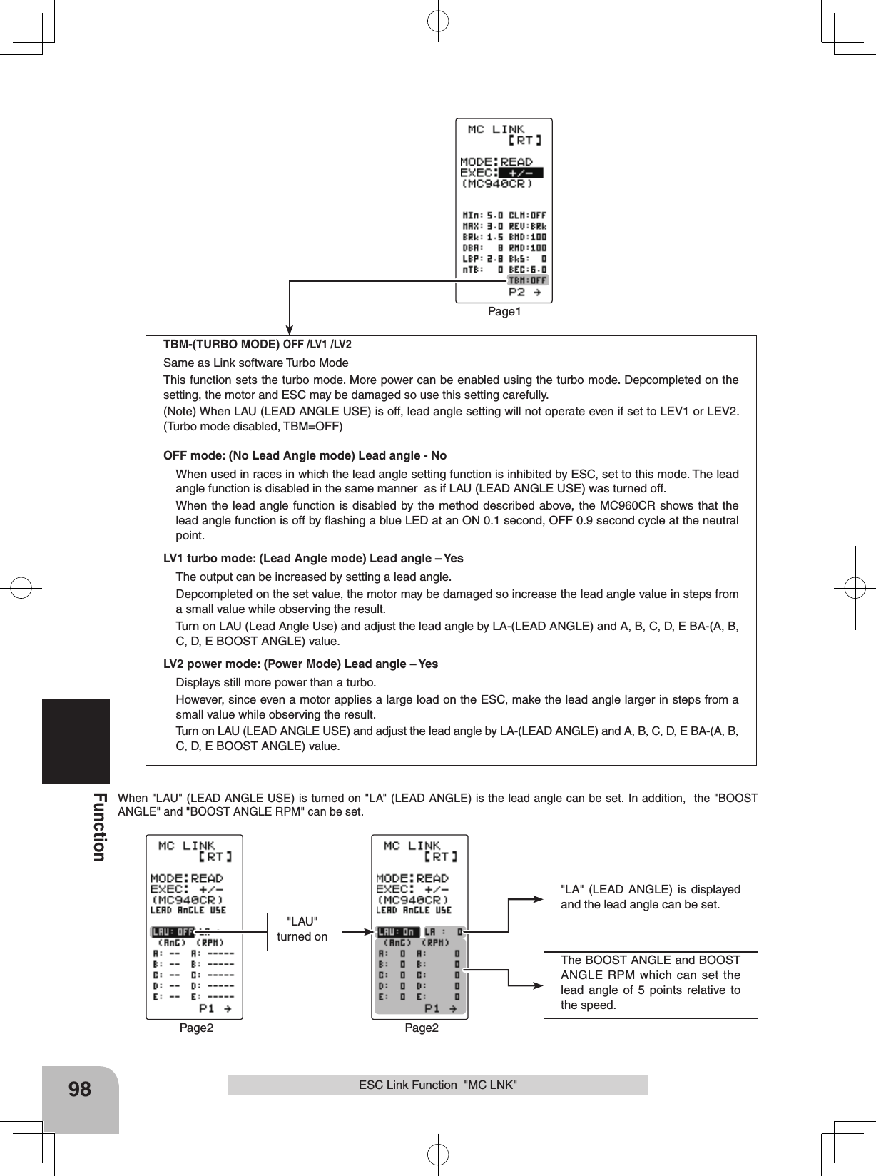
![Buzzer tone (BUZZER) OFF, 1~100 Initial value: 85Voltage display When BATT is set to dry cell use DRY4 or LiFe2/NiMH5, the voltage display of the HOME screen changes.CONTRALHT-TMBK-LHTSYSTEM[ RT ]LHT-PWBATTOPE-TMBUZZERMENUTH-STKDISPOFFTLMTRENG5 50ALL10s15DRY465DRY4 LiFe2, NiMH5The power off forgotten alarm (OPE-TM) 10m, OFFCONTRALHT-TMBK-LHTSYSTEM[ RT ]LHT-PWBATTOPE-TMBUZZERMENUTH-STKDISP TLMTRENG5 50ALL10s15DRY465OFF111FunctionNote: If used with the incorrect setting, a normal low battery alarm will not be gen-erated and the system may stop before the battery alarm is generated. The usage time may also become extremely short."LiFe2" :Futaba LiFe type battery (FT2F1700BV2 / 2100BV2)"NiMH5" :Futaba MiMH type battery (HT5F1800B)"DRY4" :Dry cell battery (alkaline battery recommended) 4 batteriesSystem Functions "SYSTEM"When completed, return to the menu screen by pressing the (JOG) button.(Adjusting the buzzer tone)Select the setting item "BUZZER" using the (JOG) button, and use the (+) and (-) buttons to adjust the tone.- Decide by referring to the tone at adjustment.When completed, return to the menu screen by pressing the (JOG) button.(Changing the Alarm Setting if Tx is left switched ON)Select the setting item "OPE-TM" using the (JOG) button, and use the (+) and (-) buttons to select the alarm setting if Tx is left switched ON mode."10m" :If an operation is not performed within 10 min-utes while the power is on, an audible alarm sounds."OFF" :Alarm setting if Tx is left switched ON is OFFWhen completed, return to the menu screen by pressing the (JOG) button.](https://usermanual.wiki/Futaba/T4GRS-24G.User-Manual-Part-3/User-Guide-2495376-Page-26.png)
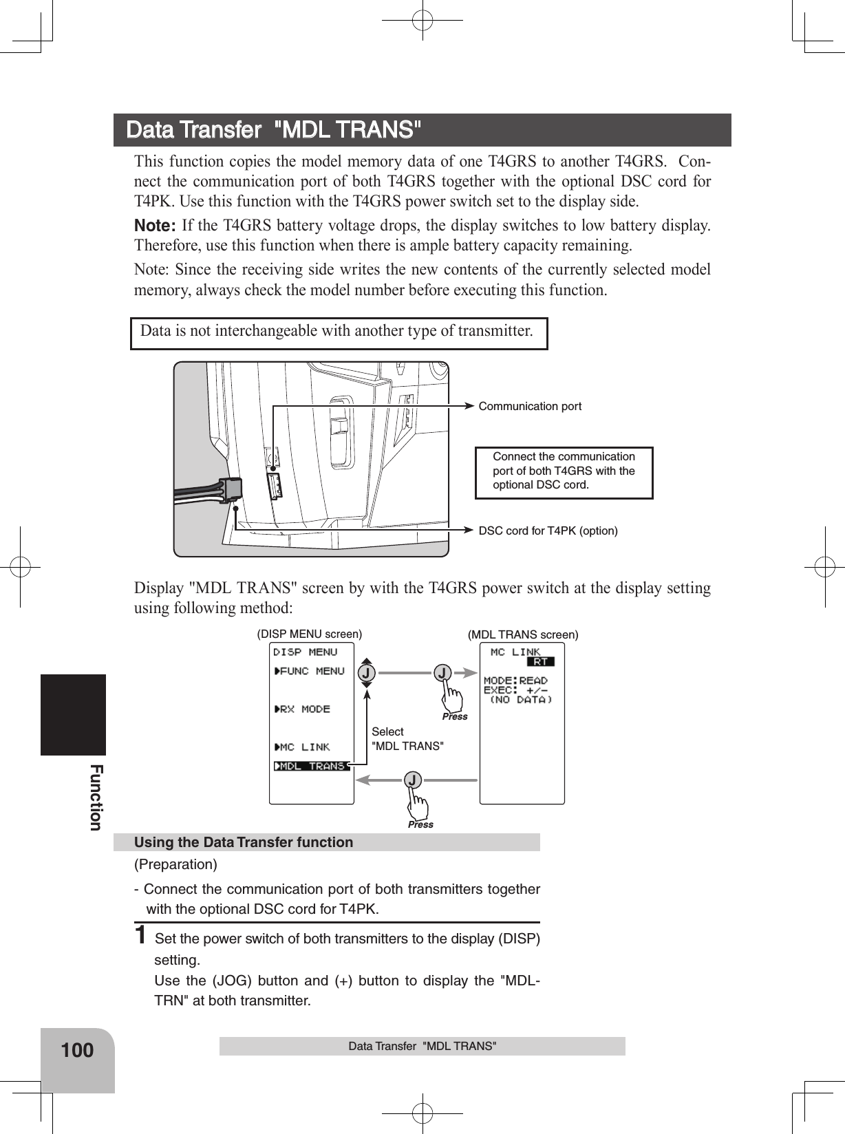
![CONTRALHT-TMBK-LHTSYSTEM[ RT ]LHT-PWBATTOPE-TMBUZZERMENUTH-STKDISP5 50ALL10s15DRY465OFFENGTLMTRUSERTIMERTLMTRMenu character (MENU) ENG, CONTRALHT-TMBK-LHTSYSTEM[ RT ]LHT-PWBATT DRY4OPE-TMBUZZERMENUTH-STKDISP0ALL10s1565OFFTLMTR5 5ENGThrottle stick (TH-STK) 5:5, 7:3, F10 (forward only)CONTRALHT-TMBK-LHTSYSTEM[ RT ]LHT-PWBATT DRY4OPE-TMBUZZERMENUTH-STKDISP0ALL10s1565OFFTLMTRENG5 5HOME screen mode (DISP) TLMTR, TIMER, USERWhen changed into F10 (forward only), brake set-up cannot be activated. The display of "NO BRAKE" or " ---" comes out on each screen, and a setup is impossible. GR112FunctionSystem Functions "SYSTEM"(Changing the menu character display)Select the setting item "MENU" using the (JOG) button, and set the basic menu char-acter display with the (+) or (-) button. "ENG" : Basic menu displayed in Alphabetic character." " : Basic menu displayed in katakana character.When completed, return to the menu screen by pressing the (JOG) button.(When the neutral adjuster of throttle stick is changed )Select the setting item "TH-STK" using the (JOG) button, and set the neutral adjuster po-sition mode with the (+) or (-) button."5:5" :Normal"7:3" :Forward stick travel is increased"F10" :When ratchet is being used (for GP boat) Press the (JOG) button after thoroughly checking whether or not the mistake was made again. An electronic beeping sound is generated and the setting is changed.When completed, return to the menu screen by pressing the (JOG) button.(Changing the HOME screen display mode)Select the setting item “DISP” using the (JOG) button, and set the HOME screen display mode with the (+) or (-) button.“TLMTR” :Telemetry data is displayed“TIMER” :Timer is displayed“USER” :User name is displayed Only the T-FHSS system can display telemetry data. Nothing is displayed with an S-FHSS/FHSS system.](https://usermanual.wiki/Futaba/T4GRS-24G.User-Manual-Part-3/User-Guide-2495376-Page-27.png)
![fig-1fig-4fig-2 fig-3PressPressADJUSTER*STEERING*THROTTLE[ RT ]PressPressSelect "ADJUSTER"113FunctionAdjuster "ADJUSTER"(Preparation)On the ADJUSTER screen, select the setting item "Steering" using the (JOG) button, and pressing the (JOG) button.1 (Steering neutral adjustment)In the neutral setup screen (fig-1) state, pull the stick back slightly then allow to return to neutral and press the (JOG) button whilst ensuring the stick is not touched.2 (Steering throw adjustment)In the throw setup screen state (fig-2), lightly turn the stick fully to the left or right and when button mark (fig-3) is dis-played, pressing the (JOG) button.Internal check is performed automatically. When each adjust-ment point is within a fixed range, correction is performed and "COMPLETE" (fig-4) is displayed.If an adjustment point is not within a fixed range, correction is not performed and the correction data is not updated.When button mark is not displayed even though correction was performed again, please contact a Futaba Radio Control Customer Center.3When completed, return to the MENU2 screen by pressing the (JOG) button. Steering adjustmentAdjuster "ADJUSTER"Steering stick and throttle stick neutral position and servo operating angle correction can be applied. This is used when a mechanical offset has occurred for some reason. *However, when correction is made, the set value of all the setting functions must be rechecked.Display the adjuster screen from the system menu.(HOME screen) (MENU 1 screen) (ADJUSTER screen)(MENU 2 screen)](https://usermanual.wiki/Futaba/T4GRS-24G.User-Manual-Part-3/User-Guide-2495376-Page-28.png)
![5:5 7:3Neutral Adjuster(Throttle stick)114FunctionAdjuster "ADJUSTER"(Preparation)On the ADJUSTER screen, select the setting item "THROT-TLE" using the (JOG) button, and press the (JOG) button.Throttle adjustment will not be made if it has been converted to ratchet operation. It is necessary to return to a self neutral. Throttle adjustmentKeyCANCELADJUSTERTHROTTLEN5 5KeyCANCELADJUSTERTHROTTLEN5 5N7 3KeyCANCELADJUSTERTHROTTLEN5 5N7 3BRKFWDKeyCANCELADJUSTERTHROTTLEN5 5N7 3BRKFWDfig-1fig-3fig-2fig-41 (Throttle 5:5 neutral adjustment )Neutral adjuster is set to 5:5 by the Neutral Adjuster switch. In the 5:5 neutral setup screen (fig-1) state, pull the stick back slightly then allow to return to neutral and press the (JOG) button whilst ensuring the stick is not touched.2 (Throttle 7:3 neutral adjustment )Neutral adjuster is set to 7:3 by the Neutral Adjuster switch. In the 7:3 neutral setup screen (fig-2) state, pull the stick back slightly then allow to return to neutral and press the (JOG) button whilst ensuring the stick is not touched.Note that both the 5:5 and 7:3 neutral adjustment procedures have to be completed as part of the set-up process. Once complete the required option should be selected. 3 (Throttle throw adjustment)In the throw setup screen state (fig-3), gently move the stick fully to the brake side and the forward side and when button mark (fig-4) is displayed, pressing the (JOG) button.Internal check is performed automatically. When each adjust-ment point is within a fixed range, correction is performed and “COMPLETE!” (fig-5) is displayed.If an adjustment point is not within a fixed range, correction is not performed and the correction data is not updated.When button mark is not displayed even though correction was performed again, please contact a Futaba Radio Control Customer Center.4When completed, return to the ADJUSTER screen by press-ing the (JOG) button. 5Next, move the cursor to [RT] using the (JOG) button, and press the (JOG) button. KeyCANCELADJUSTERTHROTTLEN5 5N7 3BRKFWDCOMPLETE!fig-5](https://usermanual.wiki/Futaba/T4GRS-24G.User-Manual-Part-3/User-Guide-2495376-Page-29.png)
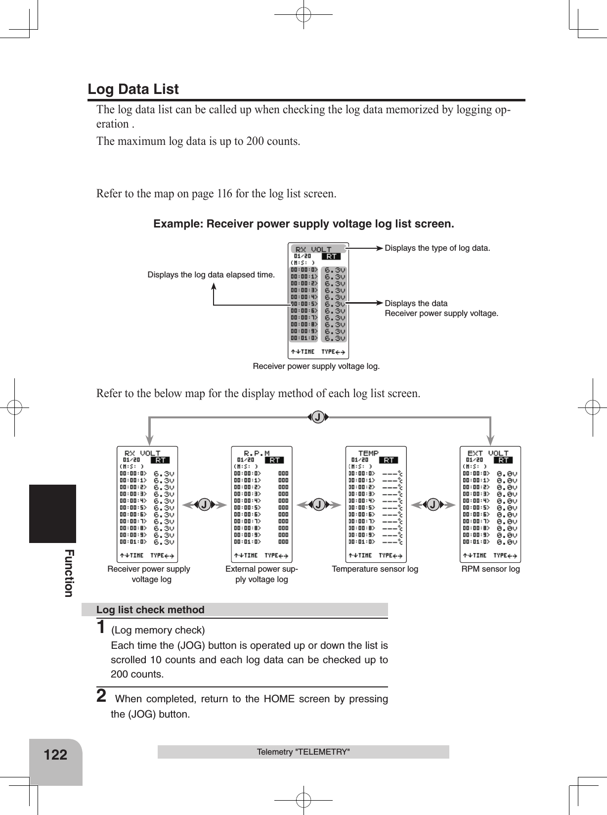
![(Sensor Set Screen)(Log Set Screen)(Telemetry Function ON/OFF Screen)(HOME screen)PressPressPressPressPressPressPressPressPressPressp.117p.120p.118The cursor on [RT] The cursor on [RT] (Log Data Screen)116FunctionTelemetry "TELEMETRY"Telemetry/Log Screen Map](https://usermanual.wiki/Futaba/T4GRS-24G.User-Manual-Part-3/User-Guide-2495376-Page-31.png)
![Function ON/OFF (MODE) INH, ACTSelect button- Select with the (+) or (-) but-tons.Telemetry function :OFF- Telemetry function :ON- Receiver ID before setting or ID mis-match.- When the receiver ID is set, before ID check in the receiver power OFF state.- Telemetry function :ON- Receiver ID setting complete.- Data receiving sensitivity display.- shows that data cannot be received be-cause it is outside the data receiving range or because of the effects of an obstruction or the receiver power is OFF after receiver ID check. Receiver -> Transmitter: The reception strength is shown.The reception strengthNo signal receptionHighLowTelemetry turned ON, LED of the jog key will blink twice. 117FunctionTelemetry "TELEMETRY"(HOME screen)Temperature Sensor infoRPM Sensor info Receiver voltage infoVoltage Sensor info(TELEMETRY ON/OFF screen)Temperature Sensor infoRPM Sensor infoReceiver voltage infoVoltage Sensor infoTelemetry Function ON/OFFThe telemetry data can be viewed at the HOME screen and telemetry ON/OFF screen. The telemetry function can also be turned on and off at the telemetry ON/OFF screen. The telemetry ON/OFF and communication status can be checked at the HOME screen.Refer to the map on page 116 for the telemetry ON/OFF (telemetry) screen display.(Preparation)- On the HOME screen, open the TELEMETRY ON/OFF screen by pressing the (+) button.1Select the setting item "MODE" using the (JOG) button up or down operation. Set the function by pressing the (+) or (-) button."OFF" : Function OFF"ON" : Function ON2When completed, move the cursor to [RT] by the (JOG) but-ton, and return to the HOME screen by pressing the (JOG) button.Telemetry function ON/OFF](https://usermanual.wiki/Futaba/T4GRS-24G.User-Manual-Part-3/User-Guide-2495376-Page-32.png)
![Alarm ON/OFF ON, OFF- Select with the (+) or (-) but-tons.Voltage alarm 3.8V~8.0V Initial value: 5VAdjust button- Adjust with the (+) and (-) but-tons.- Return to the initial value "0" by pressing the (+) and (-) buttons simultaneously for about 1 sec-ond.118FunctionTelemetry "TELEMETRY" Receiver power sup-ply voltage setting External power supply Voltage sensor settingPage1 Temperature sensor setting RPM sensor settingPage2Telemetry Sensor SettingAn audible alarm can be generated by the T4GRS from the data from a telemetry sen-sor. This setting sets alarm ON/OFF and the alarm conditions.Refer to the map on page 116 for the sensor setting (SENS MODE) screen display.There are receiver power source (battery) voltage and external power source (drive bat-tery) voltage settings on page 1 of the sensor setting screen and temperature and speed settings on page 2. Pages 1 and 2 are switched by (JOG) button left or right operation. (Setting of each item)Setting the receiver power supply voltage alarmDisplay page 1 using (JOG) button left or right operation.Select "ALRM" of the "*RX VOLT" setting items using (JOG) button up or down opera-tion, and set alarm ON/OFF with the (+) but-ton or (-) button."OFF" : Alarm OFF"ON" : Alarm ON by a voltage drop below the specified voltageSelect "VOLT" of the "*RX VOLT" setting items using (JOG) button up or down operation, and set the voltage at which the alarm begins to sound with the (+) button or (-) button. The number of digits can be shifted using (JOG) button left or right operation.When completed, move the cursor to [RT] using the (JOG) button, and return to the HOME screen by pressing the (JOG) button twice.Setting method](https://usermanual.wiki/Futaba/T4GRS-24G.User-Manual-Part-3/User-Guide-2495376-Page-33.png)
![Alarm ON/OFF ON, OFF- Select with the (+) or (-) but-tons.Voltage alarm 0.0V~90.0V Initial value: 5VAdjust button- Adjust with the (+) and (-) but-tons.- Return to the initial value "0" by pressing the (+) and (-) buttons simultaneously for about 1 sec-ond.Sensor typeSBS-01T, Temp 125Select button- Select with the (+) or (-) but-tons.Display type °C, °F - Select with the (+) or (-) but-tons.Alarm ON/OFF ON, OFF- Select with the (+) or (-) but-tons.Temperature alarm -20~200°C/ -4~392°F Initial value: 200°C/ 212°FAdjust button- Adjust with the (+) and (-) but-tons.- Return to the initial value "0" by pressing the (+) and (-) buttons simultaneously for about 1 sec-ond.119FunctionTelemetry "TELEMETRY"Setting external power supply voltage alarmDisplay page 1 using (JOG) button left or right operation.Select "ALRM" of the "EXT VOLT" setting items using (JOG) button up or down opera-tion, and set alarm ON/OFF with the (+) but-ton or (-) button."OFF" : Alarm OFF"ON" : Alarm ON by a voltage drop below the specified voltageSelect "VOLT" of the "*EXT VOLT" setting items using (JOG) button up or down operation, and set the voltage at which the alarm begins to sound with the (+) button or (-) button. The number of digits can be shifted using (JOG) button left or right operation.When completed, move the cursor to [RT] using the (JOG) button, and return to the HOME screen by pressing the (JOG) button twice.Setting the temperature alarmDisplay page 2 using (JOG) button left or right operation.Select "UNIT" of the "*TEMP" setting items using (JOG) but-ton up or down operation, and select Celsius or Fahrenheit temperature display with the (+) button or (-) button."°C" : Celsius display"°F" : FahrenheitSelect "ALRM" of the "*TEMP" setting items using (JOG) button up or down operation, and set alarm ON/OFF with the (+) button or (-) button."OFF" : Alarm OFF "ON" : Alarm ON at the specified temperatureSelect "TEMP" of the "*TEMP" setting items using (JOG) button up or down operation, and set the temperature at which the alarm begins to sound with the (+) button or (-) button. Select "TYPE" of the "*TEMP" setting items using (JOG) button up or down operation, and set the type of sensor with the (+) button or (-) button"SBS-01T" : Option sensor"Temp 125" : Option sensor for EuropWhen completed, move the cursor to [RT] by the (JOG) but-ton, and return to the HOME screen by pressing the (JOG) button twice.](https://usermanual.wiki/Futaba/T4GRS-24G.User-Manual-Part-3/User-Guide-2495376-Page-34.png)
![Function ON/OFF (MODE) INH, ACT- Select with the (+) or (-) but-tons.Gear ratio (moderating ratio) 0.001~64 Initial value: 1Adjust button- Adjust with the (+) and (-) but-tons.- Return to the initial value "0" by pressing the (+) and (-) buttons simultaneously for about 1 sec-ond.120FunctionTelemetry "TELEMETRY"Setting the gear ratioDisplay page 2 using (JOG) button left or right operation. Select "RATIO" of the "R.P.M" set-ting items using (JOG) button up or down op-eration, and set the location the sensor is to actually measure and the gear ratio of the mo-tor and engine with the (+) button or (-) button. There is no alarm function. When completed, move the cursor to [RT] using the (JOG) button, and return to the HOME screen by pressing the (JOG) button twice.Log Setting Start/StopThe data from a telemetry sensor can be saved to the T4GRS as a data log. Since the data is sequentially updated, when data logging is performed, the old data is erased. Only 1 data is saved.The interval at which the data is acquired can be selected from a minimum 0.1 second to a maximum 60 seconds. Because the maximum count is 200, if the count is made 200 counts at 0.1 second intervals, 20 seconds worth of data is acquired, and if the count is made 200 counts at 60 second intervals, 3 hours 20 minutes worth of data is acquired.Data logging is started and stopped by setting SW1 set by SW/Dial function to "LOG-GER" and by switch (SW1). If the switch (SW1) is not set, data logging is started by throttle stick from the log setting screen.Data logging can also be started by throttle stick from this screen and stopped by switch (SW1) set by SW/dial function.Refer to the map on page 116 for the log setting (LOG MODE) screen display.(Preparation)When using a switch (SW1) to start and stop data logging, set SW1 to "LOGGER" by SW/dial function.- On the HOME screen, open the LOG MODE screen by pressing the (-) button.1 (Log function ON/OFF)Move the cursor to the "MODE" setting item using (JOG) button up or down operation, and turn on the log function by setting "MODE" to "ACT" by pressing the (+) button or (-) button. If "MODE" is not set to "ACT", the log function will not be performed even if the switch etc, is operated."INH" : Function OFF"ACT" : Function ONLog setting method](https://usermanual.wiki/Futaba/T4GRS-24G.User-Manual-Part-3/User-Guide-2495376-Page-35.png)
![Log recording cycle0.1~60s(sec) 0.1~10s(sec)0.1s step 10s~60s(sec)1s step Initial value: 1.0secAdjust button- Adjust with the (+) and (-) but-tons.- Return to the initial value "0" by pressing the (+) and (-) buttons simultaneously for about 1 sec-ond.Log recording time 20s (seconds)~3h 20m (3 hours 20 minutes) The maximum recordable time set by CYCL is displayed auto-matically.Status display RDY :Throttle stick operation wait STA :Logger running STP : Logger stoppedAlarm ON/OFF ON, OFF- Select with the (+) or (-) but-tons.121FunctionTelemetry "TELEMETRY"1 (Log start operation)-Start by switch (SW1) When the switch (SW1) set by SW/dial func-tion is pressed, data logging starts.-Starting by throttle stickDisplay the log setting (LOG MODE) screen and select the "STATE" setting item using (JOG) button up or down operation, and press the (JOG) button for approximately 1 second.Log function start/stop operation2 (Recording cycle setting)Select the "CYCL" setting item using (JOG) button up or down operation, and set the data acquisition interval from a minimum 0.1 sec-ond to a maximum 60 seconds with the (+) button or (-) button.The maximum recordable time set by CYCL is displayed at END TIME shown below.3 (Count alarm ON/OFF) Select the "ALRM" setting item using (JOG) button up or down operation. To sound an electronic beep at each log count, set "ALRM" to ON with the (+) button or (-) button."OFF" : Alarm OFF "ON" : Alarm ON at each log countWhen completed, move the cursor to [RT] using the (JOG) button, and return to the HOME screen by pressing the (JOG) button twice.An electronic beeping sound is generated and the "STATE" display switches from "RST" to blinking "RDY", and the logger enters the stick operation wait state. When the stick is operated in the forward direction, data logging begins. (STATE display "STA") When the end time arrives, an electronic beep sounds and data logging stops. To return to the HOME screen during data logging, move the cursor to [RT] using (JOG) button up or down operation, and press the (JOG) button or (+) button.2 (Log forced end)To abort logging, press the switch (SW1), in the same way as starting, or display the log setting (LOG MODE) screen and select the "STATE" setting item using (JOG) button up or down operation and press the (JOG) button for approximately 1 second. An electronic beeping sound is generated and logging is stopped.](https://usermanual.wiki/Futaba/T4GRS-24G.User-Manual-Part-3/User-Guide-2495376-Page-36.png)