Futaba FP-PK-FM-75B Radio Control Transmitter User Manual II
Futaba Corporation Radio Control Transmitter II
UserManual.wiki
>
Futaba
>
FP-PK-FM-75B User Manual
>
User Manual II
Contents
1.
User Manual I
2.
User Manual II
User Manual II
Navigation menu
Upload a User Manual
Namespaces
Wiki Guide
HTML
PDF
Info
Views
User Manual
Discussion / Help
Navigation
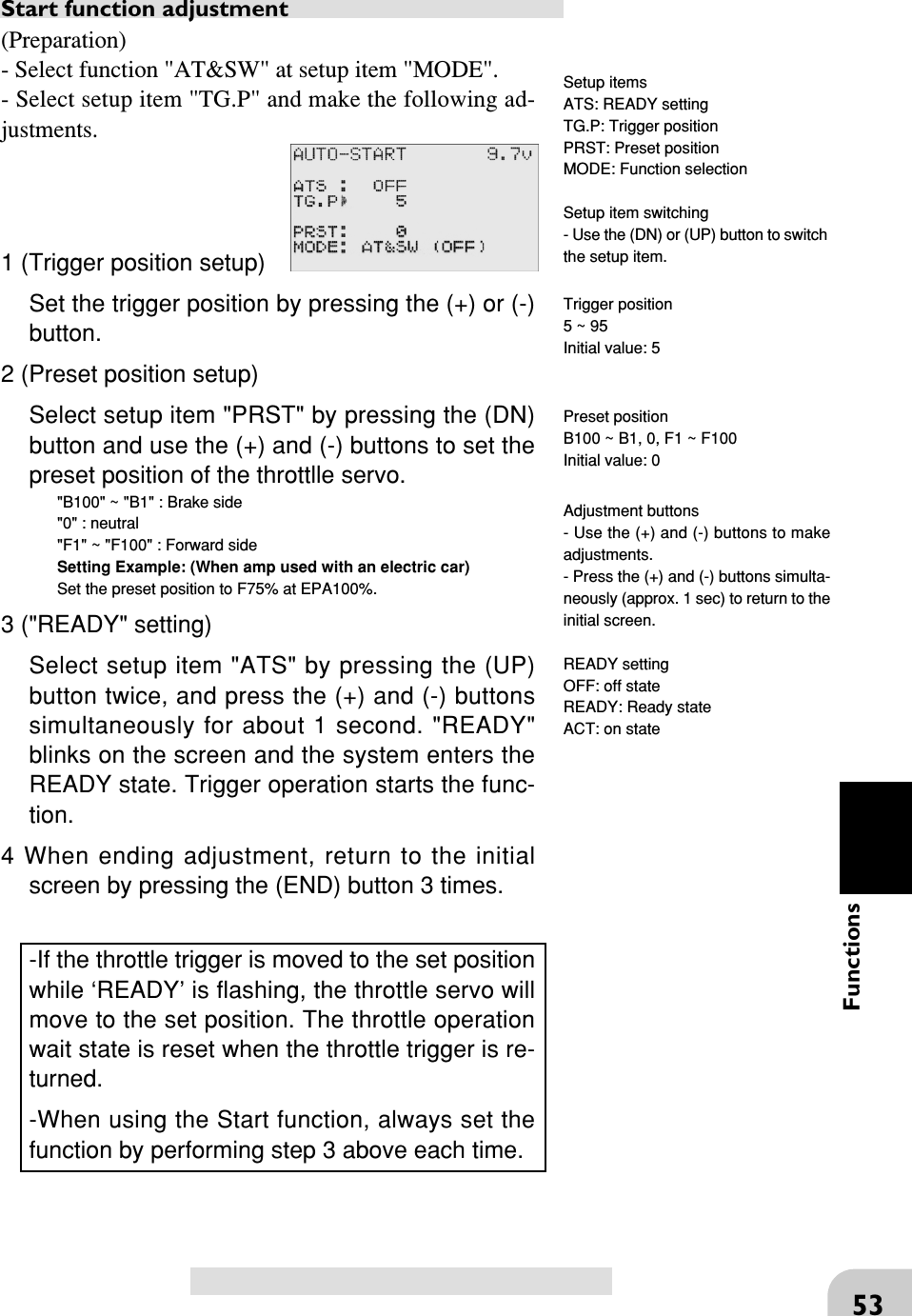
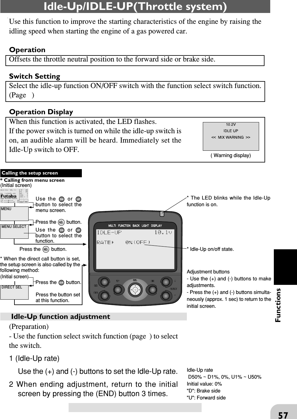
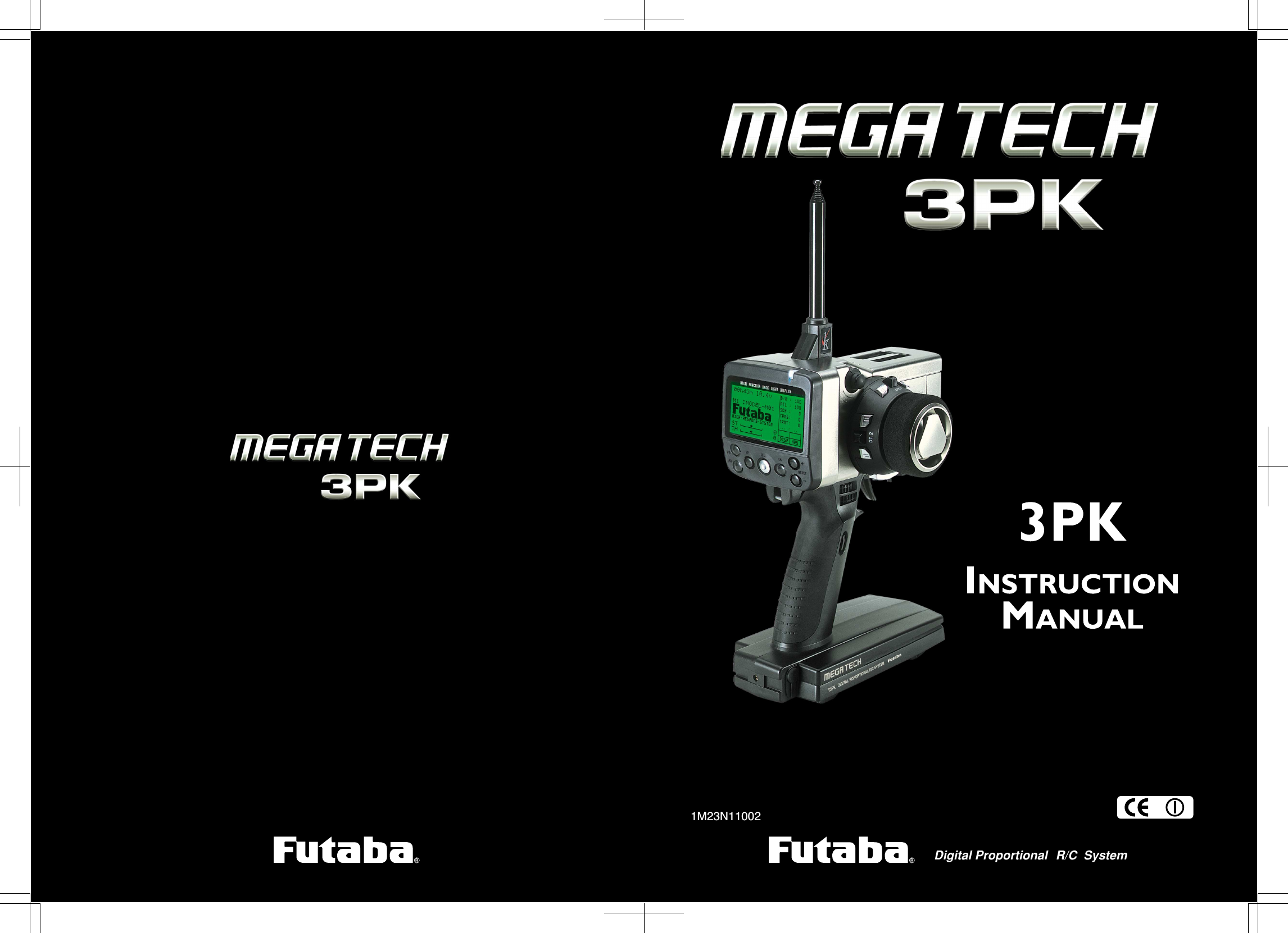
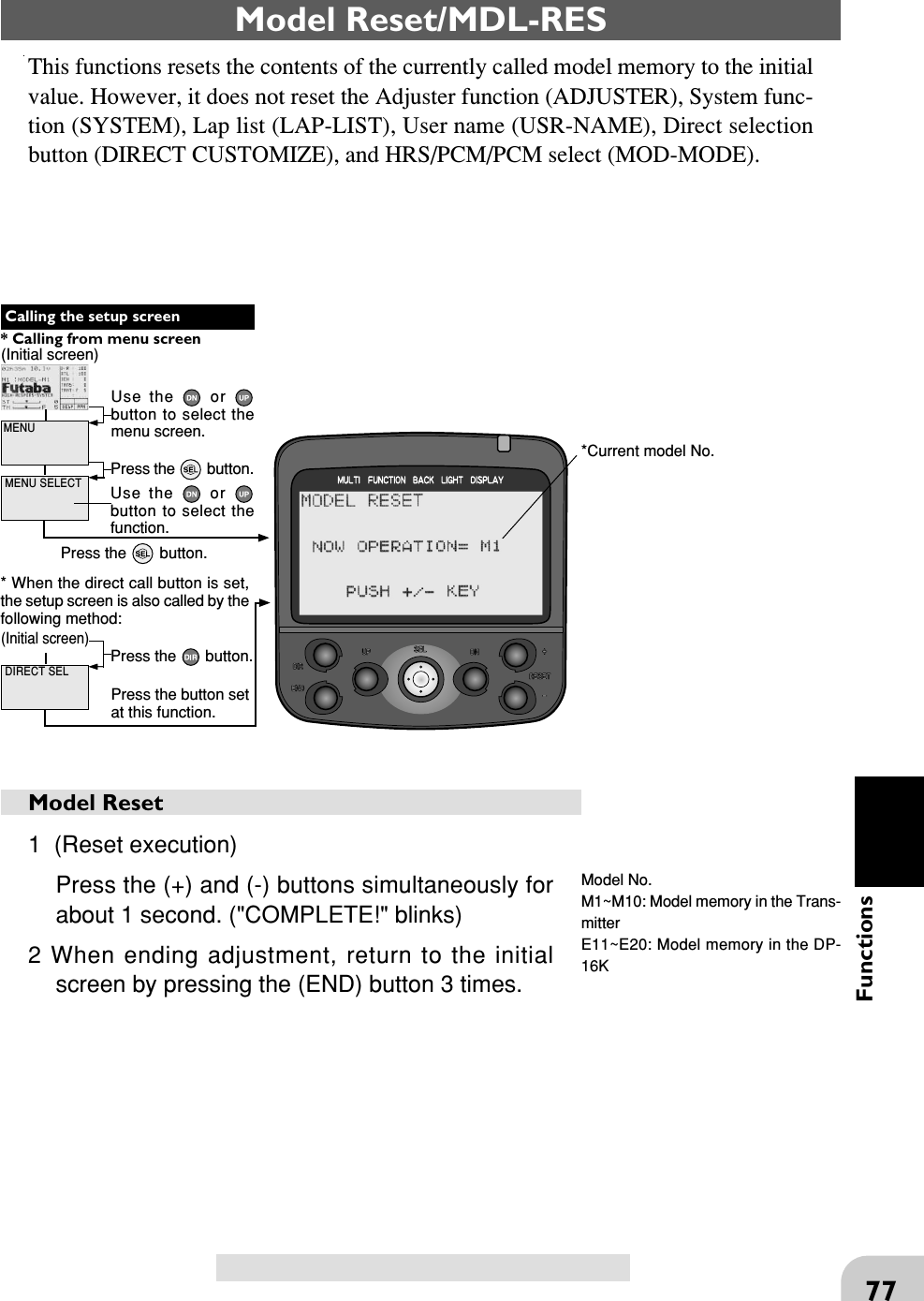
![58FunctionsTimer/TIMERUse the timer by selecting one of the four timers UP TIMER, DOWN TIMER, LAPTIMER and LAP NAVIGATE timer.UP TIMER function- The UP TIMER can be used to count the time between start and stop, etc.- The timer repeatedly starts and stops each time the switch is operated andaccumulates the time between each start and stop. (When the count reaches 99 min-utes 99 seconds, it returns to 00 minutes 00 seconds and repeats the count.)- The first start operation can be linked to the throttle trigger.- An alarm sound can be set. The passage of time is announced by sounding of abuzzer ([pee] sound) each minute after starting.Alarm: Generates a [pee] sound at the set time (min-utes).Prealarm: Alarm advance announcement sound.Sounding starts the set time (seconds) before the alarm.(PeePeePee, PeePeePee, -----)- After starting, the timer is enabled and can be stopped by switch even when thedisplay switches to another screen.UP TIMERDOWN TIMER function- The DOWN TIMER can be used to count the time between start and stop, etc. (Thetime remaining is displayed.)- Start and stop are repeated at each switch operation and the time between each startand stop is counted down and displayed. The start time becomes the alarm set time.(When the count reaches 00 minute 00 second, the down timer operates like an uptimer.)- The first start operation can linked with the throttle trigger.- An alarm sound can be set. The passage of time is announced by sounding of abuzzer ([pee] sound) each minute after starting.Alarm: Generates a [pee] sound at the set time(minute).Prealarm: Alarm advance announcement sound.Sounding starts the set time (seconds) before the alarm.(PeePeePee, PeePeePee, -----)- After starting, the timer is enabled and can be stopped by switch even when thedisplay switches to another screen.DOWN TIMER](https://usermanual.wiki/Futaba/FP-PK-FM-75B.User-Manual-II/User-Guide-856694-Page-9.png)
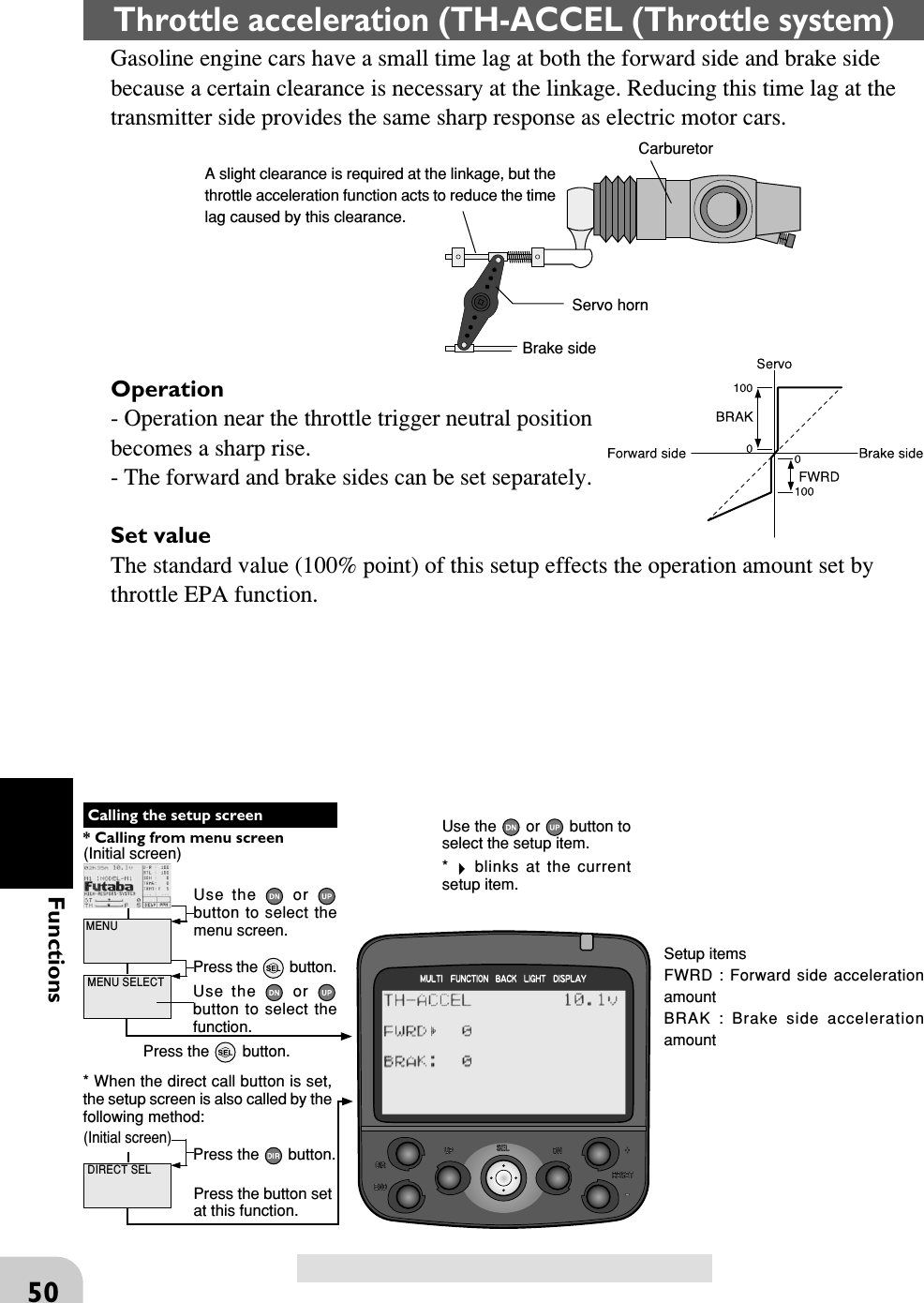
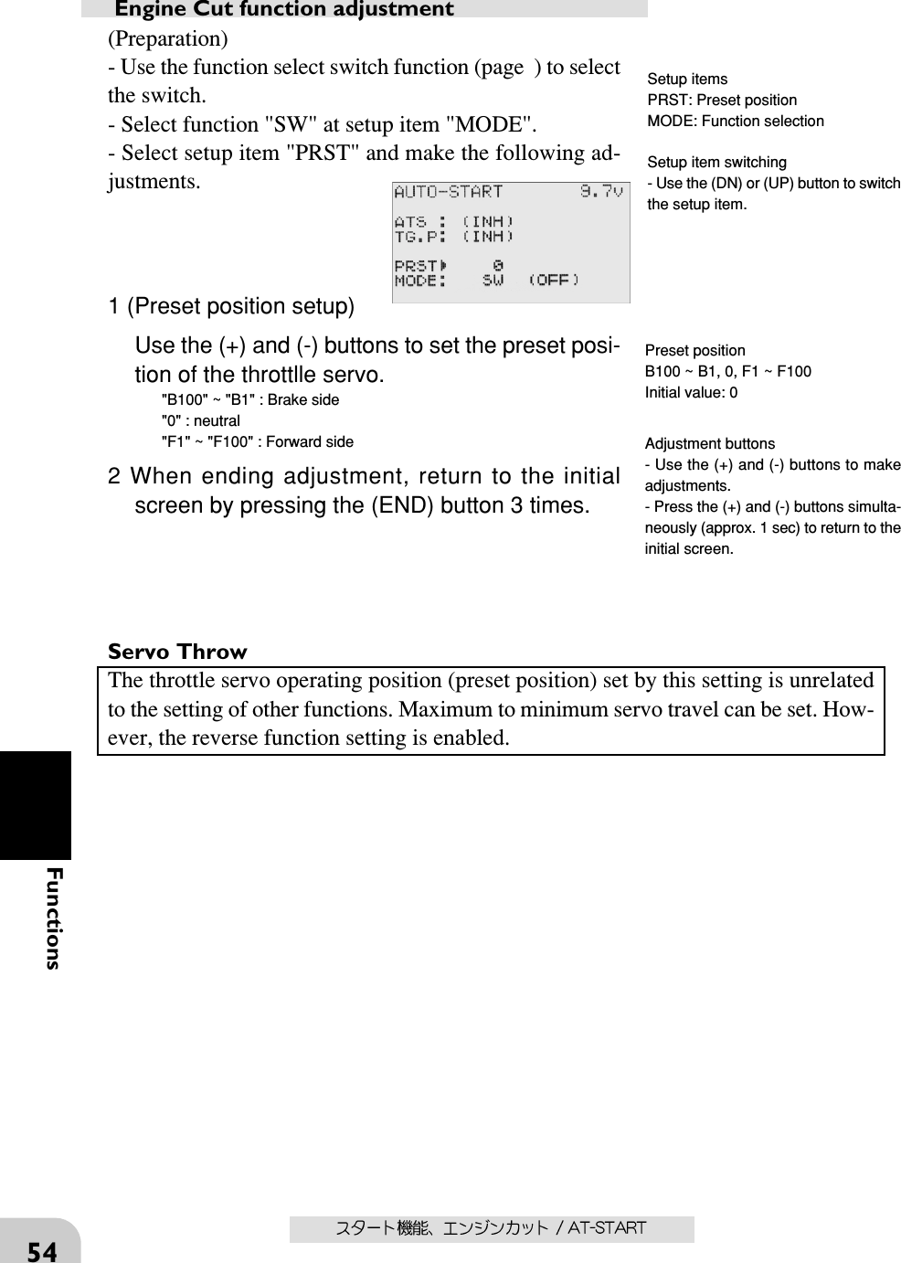
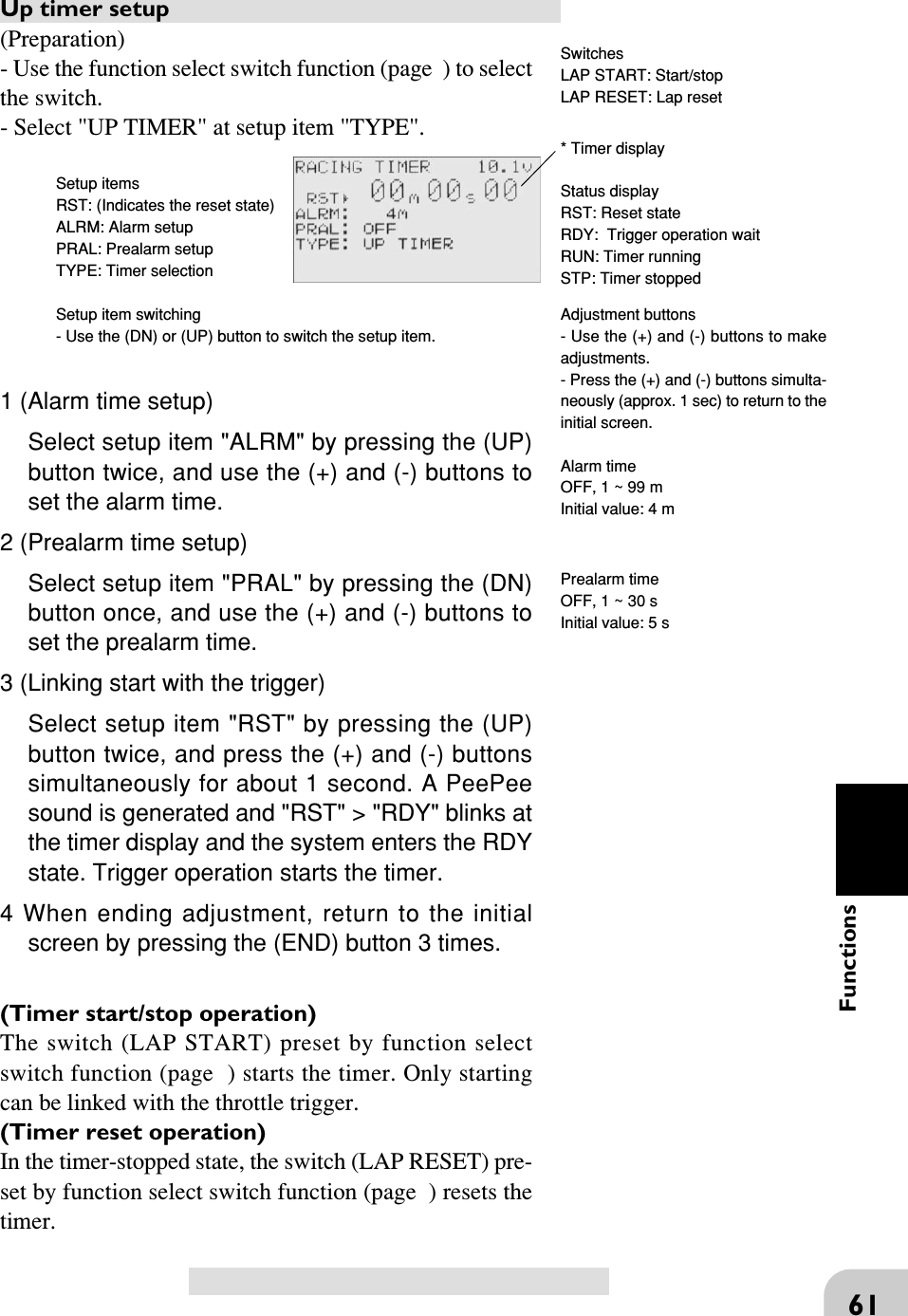
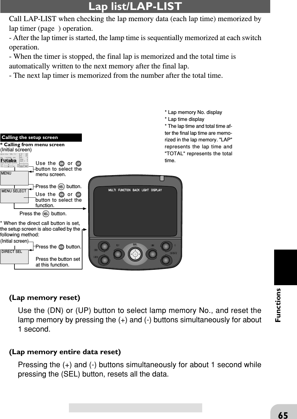
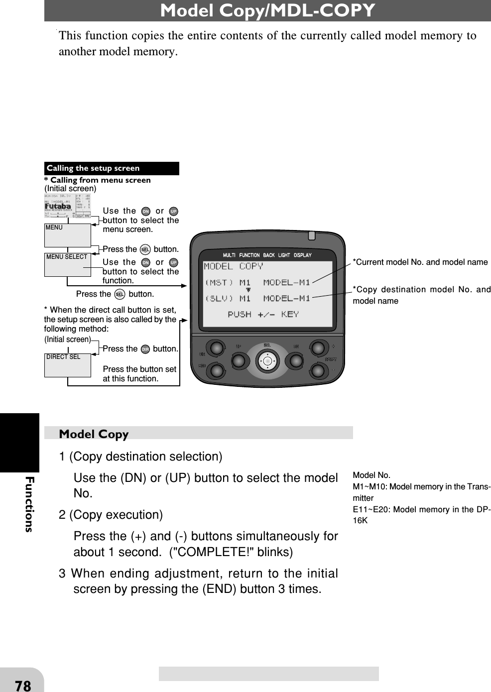
![59FunctionsLAP TIMERLAP TIMER function- The LAP TIMER can memorize each lap time of each switch operation. (99 laps)- The race time can be set. Switch operation after the set time by alarm has elapsedautomatically stops the timer.. Prealarm can also be set. The passage of time isannounced by sounding of a buzzer ([Pee] sound) each minute after starting.Alarm: Generates a [Pee] sound at the set time.Prealarm: Starts sounding the set time (second) beforethe alarm. (PeePeePee, PeePeePee, -----)- The first start operation can be linked with the throttletrigger.(LAP TIMER operation)- When lap timer is selected, the number of laps (LAP) and the lap memory No. (No.)and current lap time (TIME) are displayed on the setup screen.Number of laps (LAP): Counts up each time the switch is pressed after starting. Thenumbers blink for 3 seconds after the switch was pressed. To prevent erroneouscounting, switch operation is not accepted during this period..Lap memory No. (No.): Each lap time is memorized in a lap memory. The lap timesare written sequentially from the number after the preceding data. After lap memory"No. 100", the lap No. returns to "No. 1".The lap time data memorized in the lap memory can be checked at the lap list (page )screen.Lap time (TIME) : During the first 3seconds, the last lap time is displayed and thenthe current lamp time is displayed. At starting, "0" is displayed for 3 seconds.](https://usermanual.wiki/Futaba/FP-PK-FM-75B.User-Manual-II/User-Guide-856694-Page-10.png)
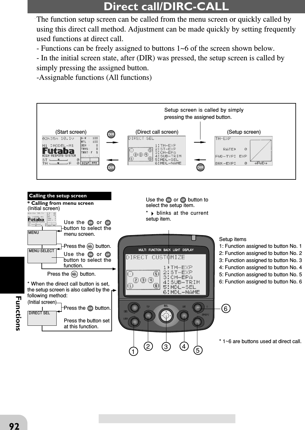
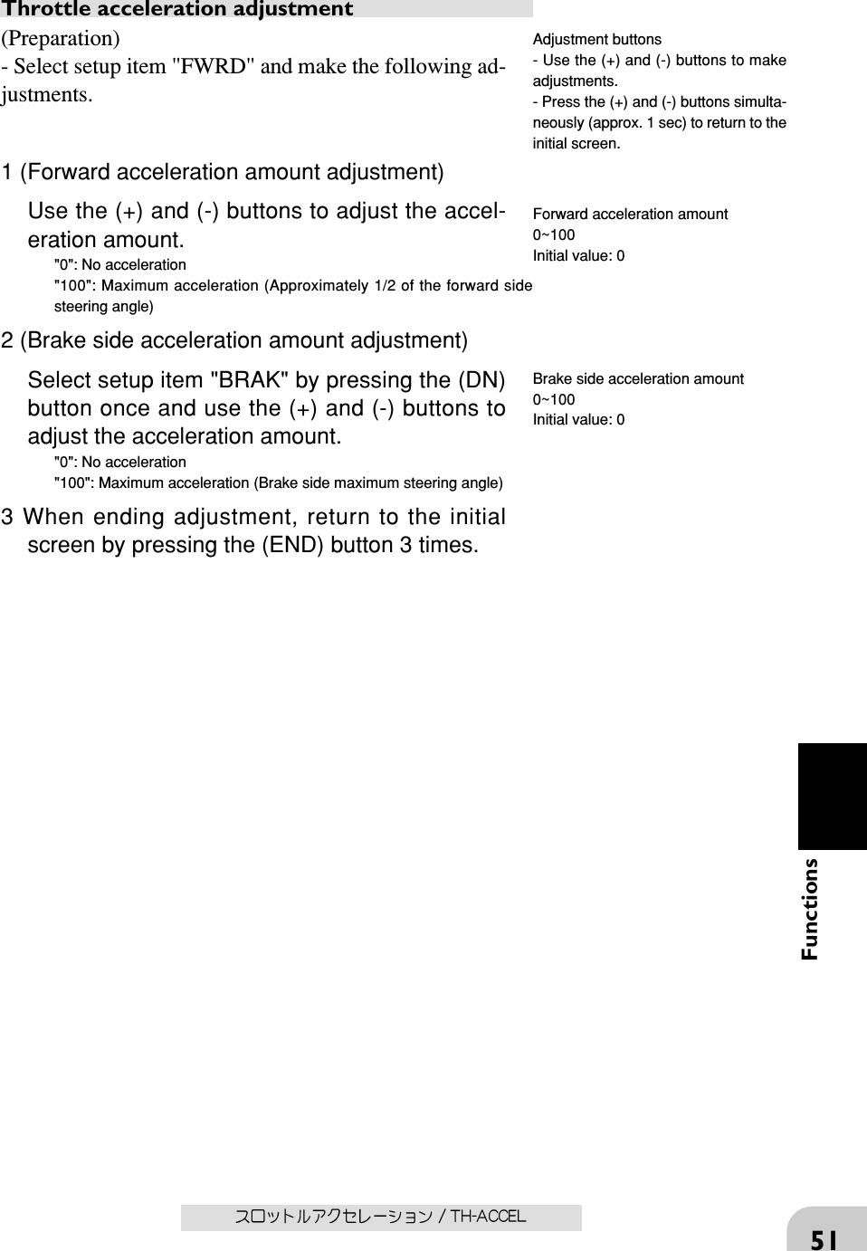
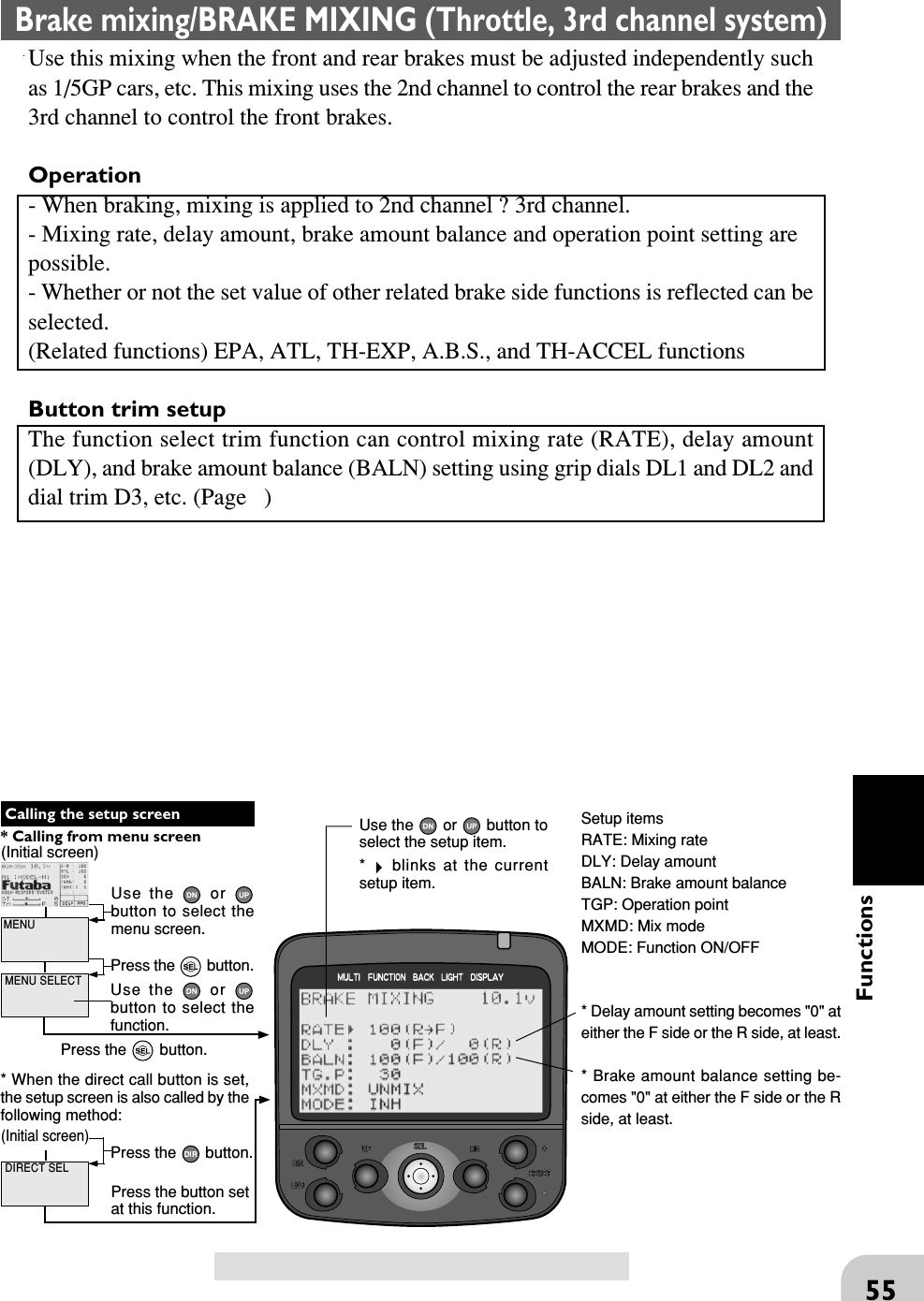
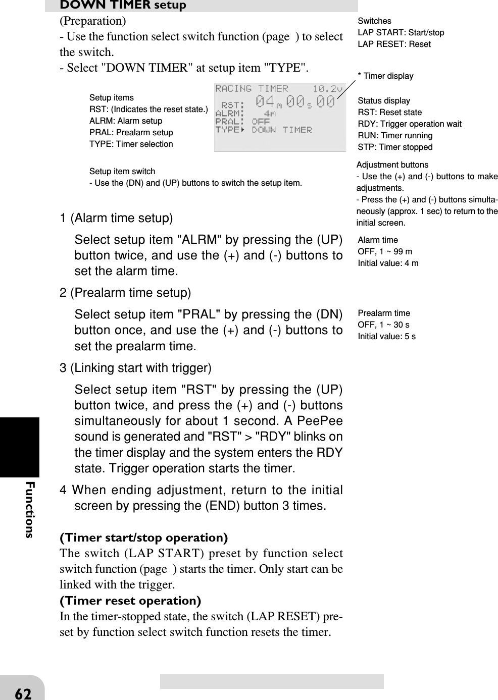
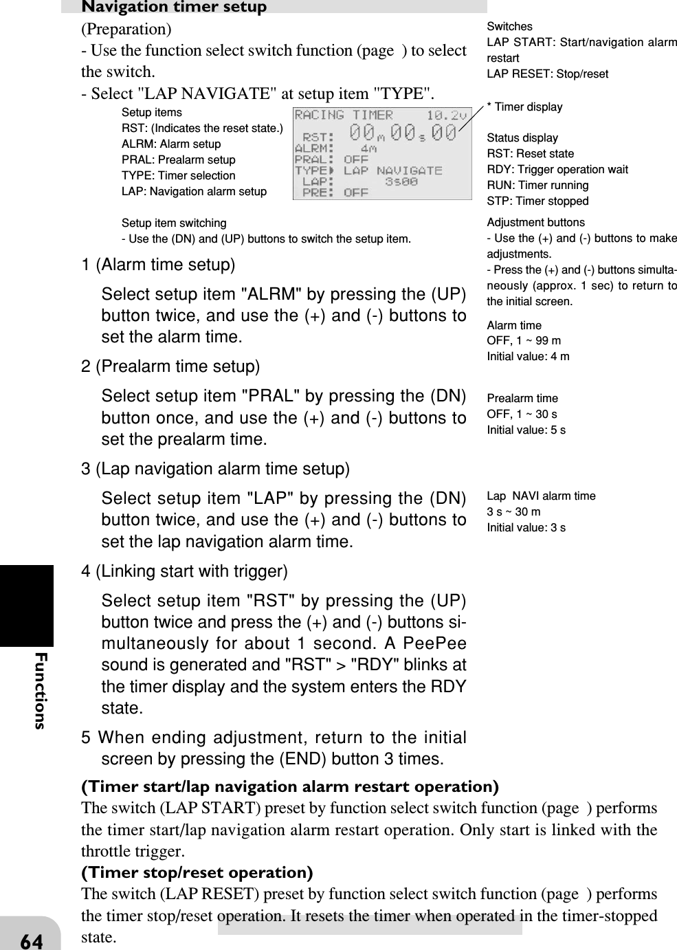
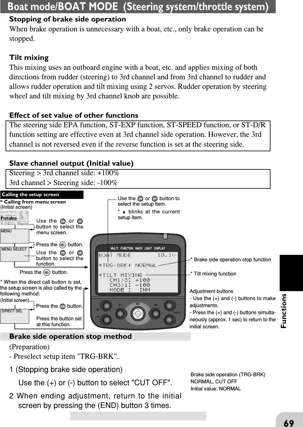
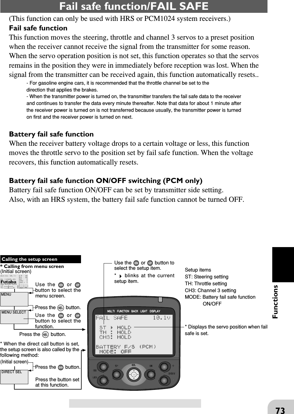
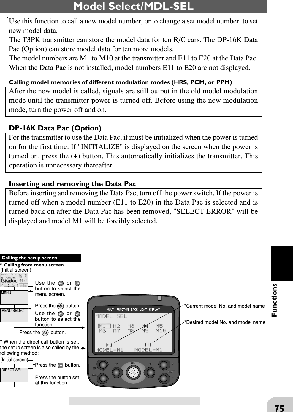
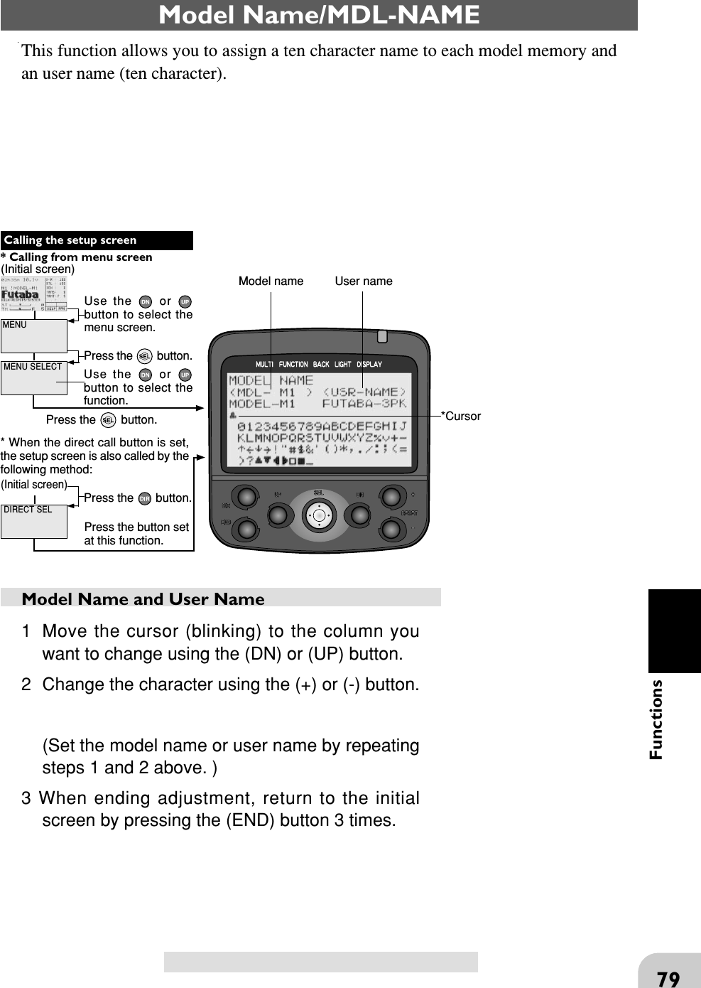
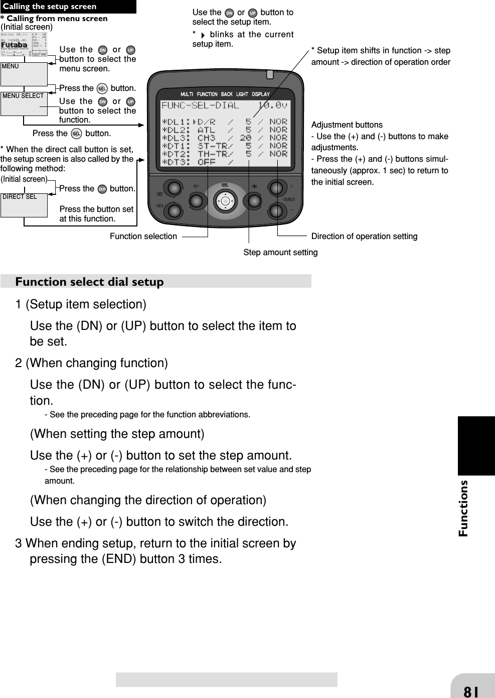
![60Functions(Initial screen) MENUUse the or button to select themenu screen.Press the button.Use the or button to select thefunction.Press the button. Calling the setup screen* When the direct call button is set,the setup screen is also called by thefollowing method: MENU SELECT DIRECT SELPress the button.Press the button setat this function.* Calling from menu screen Use the or button toselect the setup item.* blinks at the currentsetup item.(Initial screen)LAP NAVIGATE timerLAP NAVIGATE timer function- This function sounds a buzzer at a fixed interval after the timer starts. Since only thebuzzer can be restarted when the switch is pressed during timer operation, this func-tion can be used as the training run, etc. target time. (Lap navigation alarm) Thepassage of time is announced by sounding of a buzzer ([Pee] sound) every minuteafter starting.- The first start operation can be linked with the throttle trigger.- The alarm sounds (alarm/prealarm) can be set separately from the fixed intervalbuzzer.Alarm: Generates a [Pee] sound at the set time (min-utes).Prealarm: Alarm advance announcement sound.Sounding starts the set time (seconds) before the alarm.(PeePeePee, PeePeePee, -----)- After starting, the timer is enabled and can be stopped by switch even when thedisplay switches to another screen.* Minute display (m)* Second display (s)* 1/100 second displayTimer selectionFirst, select the type of timer at the"TYPE" item. The setup screenvaries depending on the type oftimer. This figure shows the UPTIMER setup screen.Timer selection (TYPE)UP TIMER: Up timerDOWN TIMER: Down timerLAP MEMORY: Lap timerLAP NAVIGATE: Navigation timer](https://usermanual.wiki/Futaba/FP-PK-FM-75B.User-Manual-II/User-Guide-856694-Page-11.png)
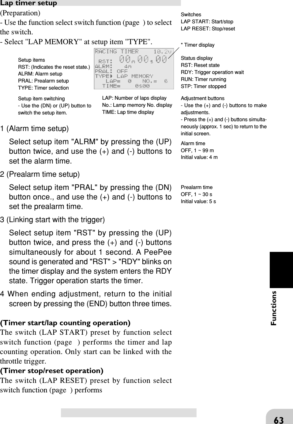
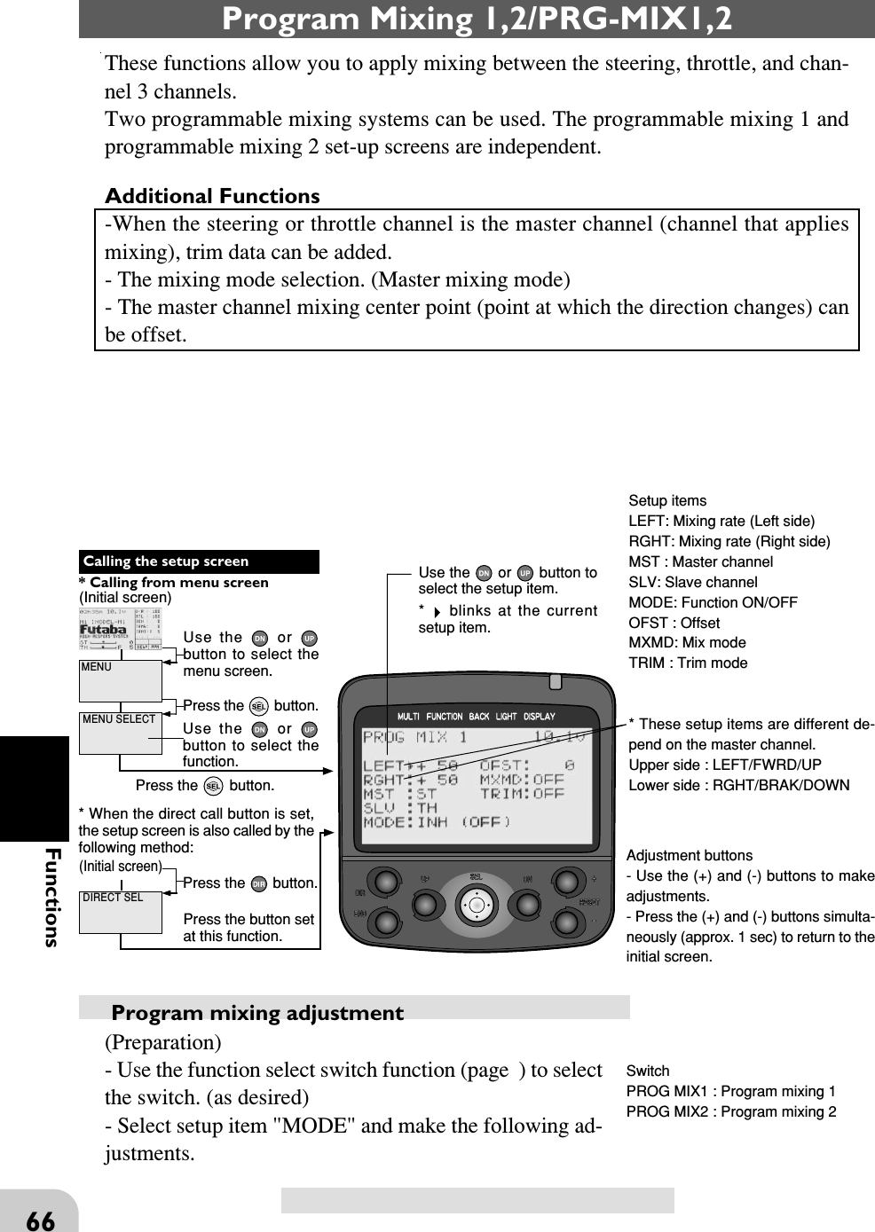
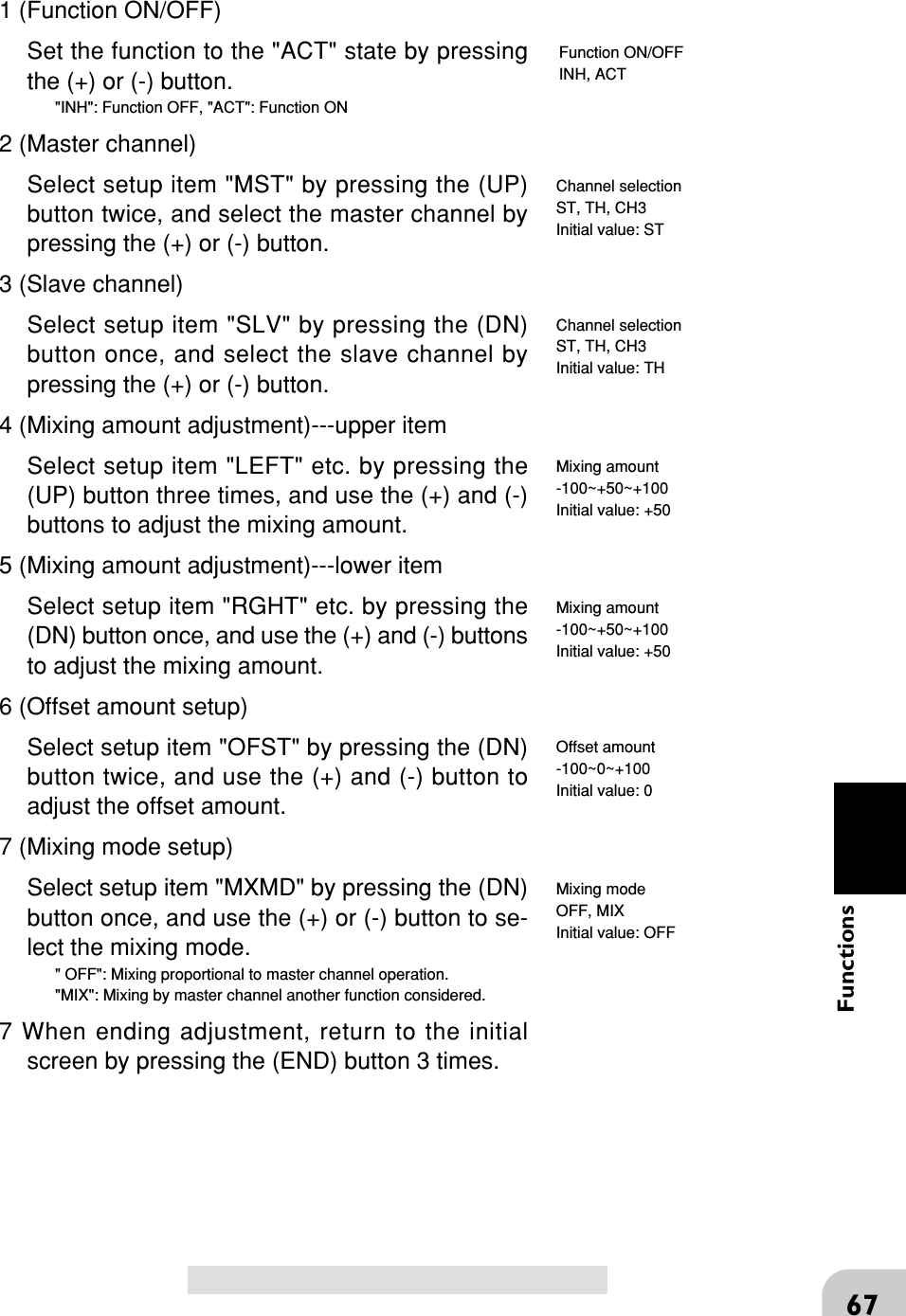
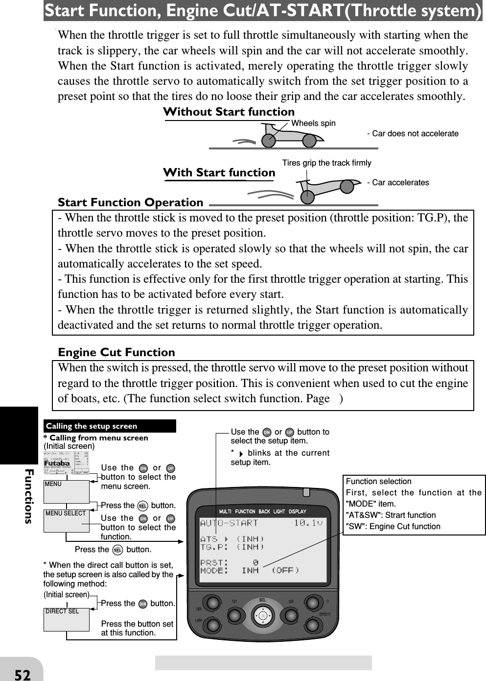
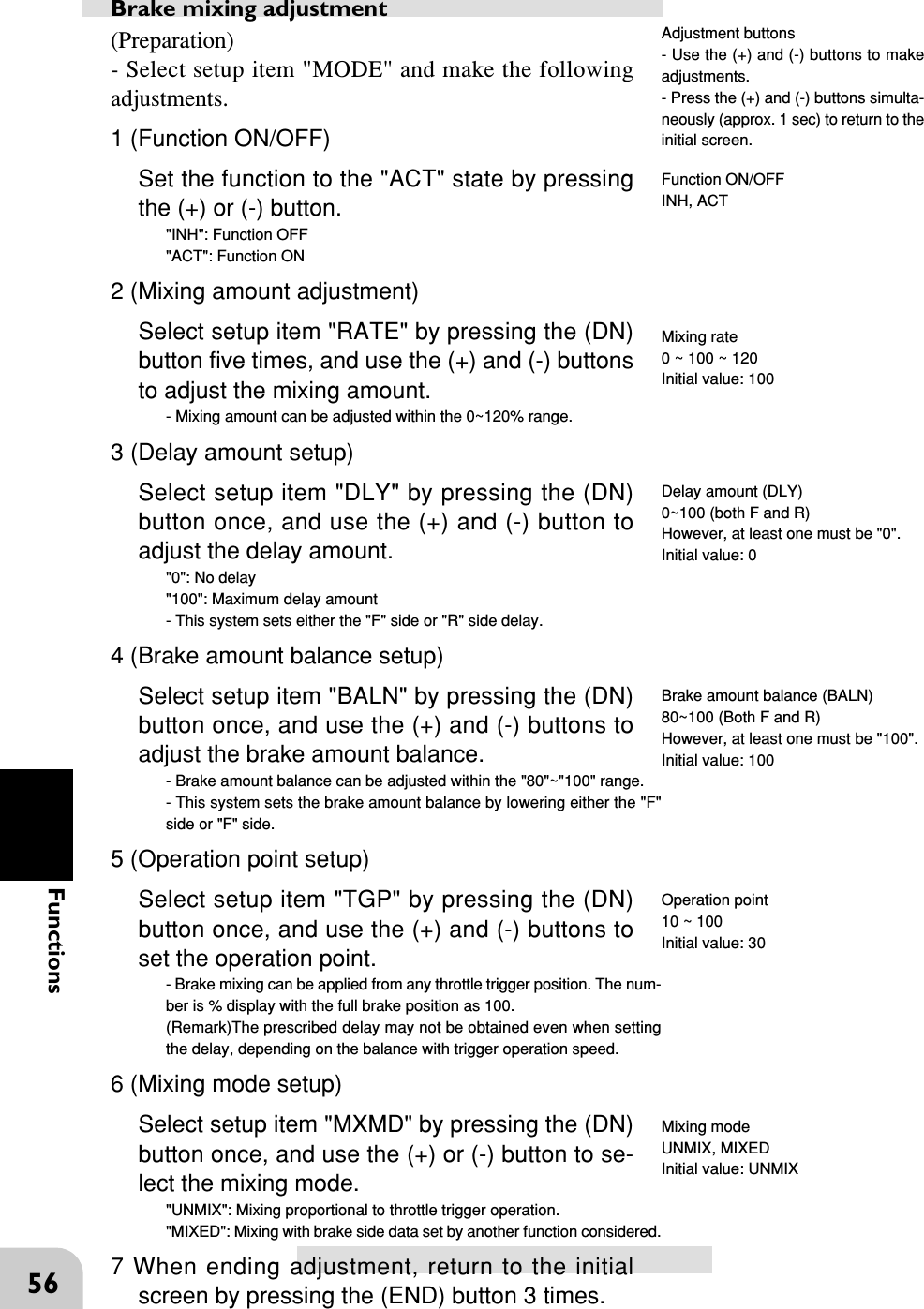
![68FunctionsWhen Steering and Throttle Travel is InsufficientWhen the steering servo travel is insufficient even when D/R is 100% and EPA is120%, programmable mixing can be used to increase the travel somewhat.(Reference data)- PM1->ON- MST (master channel) -> ST Mixing is applied from steering- SLV (slave channel) ->ST Mixing is applied to steering and the travel is increased.- RIGH -> 10% [When subtrim is centered (0%)]- LEFT -> 10% [When subtrim is centered (0%)]- Trm -> OFF- OFS -> 0%- MXMD -> MIXHowever, the operating range of the servo is exceededeven if a large value is input at RIGH and LEFT and azone over which the servo does not operate even whenthe wheel is moved to the left or right is created. A zoneover which the servo does not operate is also generatedat the moving side when the subtrim is moved to theleft and right. Therefore, set the RIGH and LEFT valueby checking servo operation.When the throttle servo travel is insufficient at ATL 100% and EPA120%, the sameaction can be performed by making TH (throttle) both the MST and SLV when steer-ing.When both steering and throttle operations are performed, use both PROG MIX1 andPROG MIX2 program mixing.Full leftZone over which servodoes not operateFull right](https://usermanual.wiki/Futaba/FP-PK-FM-75B.User-Manual-II/User-Guide-856694-Page-19.png)
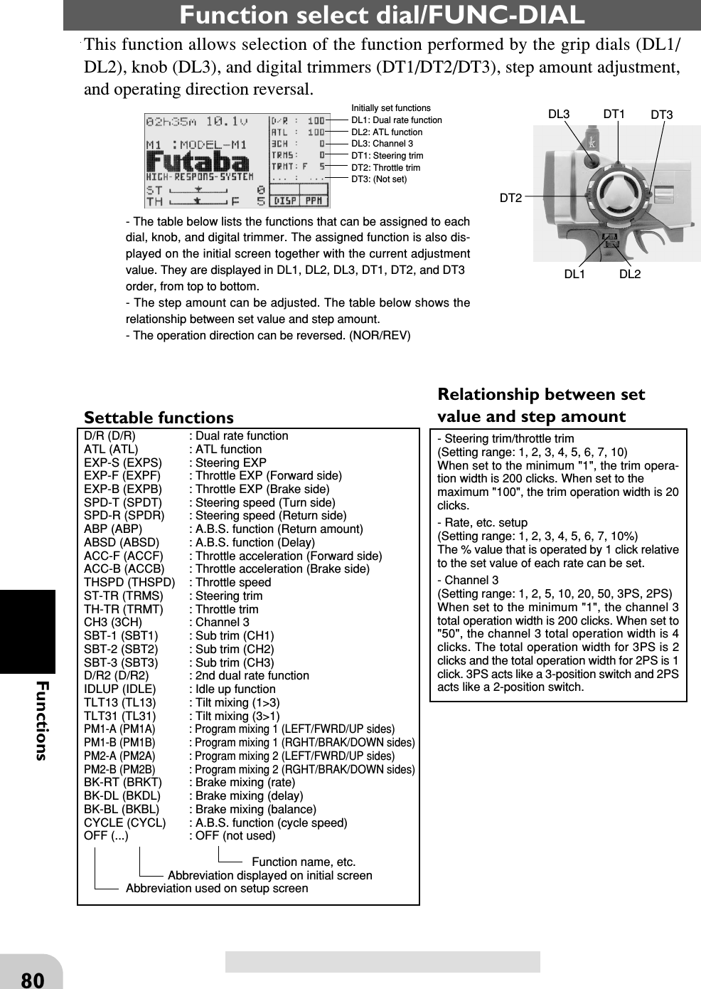
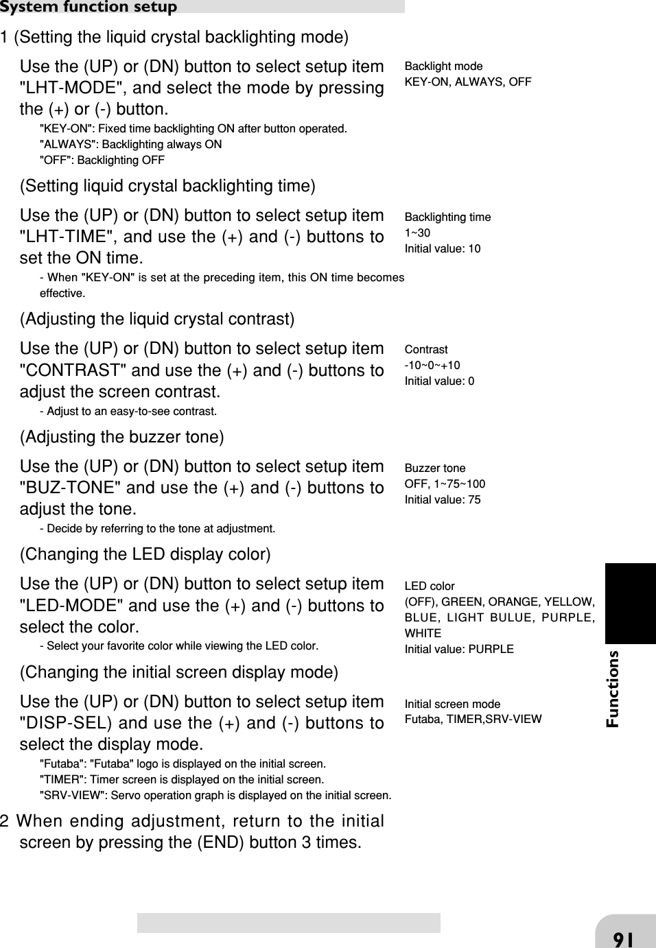
![90Functions(Initial screen) MENUUse the or button to select themenu screen.Press the button.Use the or button to select thefunction.Press the button. Calling the setup screen* When the direct call button is set,the setup screen is also called by thefollowing method: MENU SELECT DIRECT SELPress the button.Press the button setat this function.* Calling from menu screen Use the or button toselect the setup item.* blinks at the currentsetup item.(Initial screen)System function/SYSTEMThe graphic liquid crystal screen display mode, buzzer sound, pilot lamp displaymode and initial screen display mode can be set.The system function setup items cannot be set for each model.- Liquid crystal screen backlighting display mode setup (OFF, ON at button opera-tion, normally ON)- Setting of ON time (1~30 secs) when [ON at button operation] was selected above.- Liquid crystal screen contrast adjustment (20 steps)- Buzzer sound tone adjustment (OFF, 100 steps)- Pilot lamp display color setup (OFF, 7 colors)- Initial screen display mode setting ("Futaba" display, timer display, servo display)Setup itemsLHT-MODE: Backlighting modeLHT-TIME: Backlighting timeCONTRAST: ContrastBUZ-TONE: Buzzer toneLED-MODE: LED colorDISP-SEL: Initial screen mode*When "KEY-ON" was selected atbacklighting mode, "ACT" is displayedand the backlighting time setting be-comes effective.Adjustment buttons- Use the (+) and (-) buttons to makeadjustments.- Press the (+) and (-) buttons simulta-neously (approx. 1 sec) to return tothe initial screen.](https://usermanual.wiki/Futaba/FP-PK-FM-75B.User-Manual-II/User-Guide-856694-Page-41.png)