Furuno USA 9ZWWR2100 Dual Polarimetric X-band Weather Radar User Manual III
Furuno USA Inc Dual Polarimetric X-band Weather Radar III
UserManual.wiki
>
Furuno USA
>
9ZWWR2100 User Manual
>
User Manual III
Contents
1.
User Manual
2.
User Manual II
3.
User Manual III
User Manual III
Navigation menu
Upload a User Manual
Namespaces
Wiki Guide
HTML
PDF
Info
Views
User Manual
Discussion / Help
Navigation
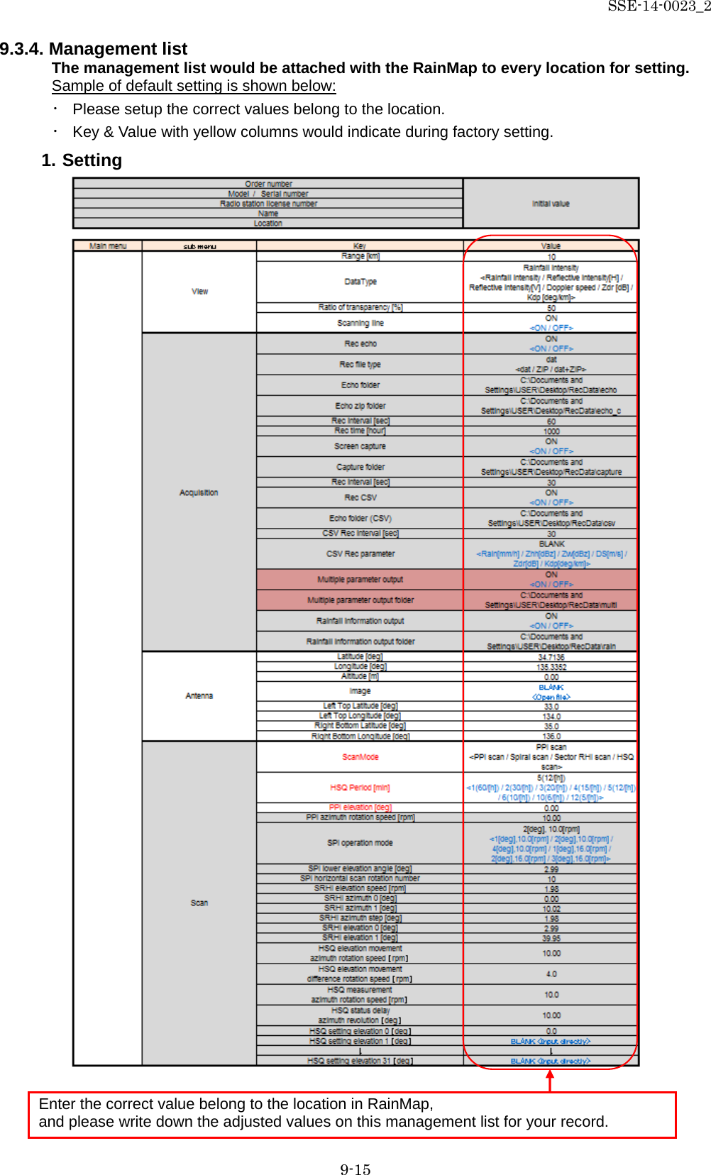
![SSE-14-0023_2 9-1 9. PC operation 9.1. File 1) File Play: To play a regular echo recorded file (idx) (Refer “2) Acquisition” on 9.3.1.) 2) Snapshot: To indicate captured radar screen (jpg). 3) Exit: To exit the software of RainMap. 4) Operation mode: (Click “File” + [Ctrl] + [Alt] at same time to Indicate the menu) Do this operation mode after changed some parameters to operate a radar. - Observation: Select the entered values at “Setting” menu with regular mode. - Verify operation during installation: Change some parameters automatically to verify operation during installation. All parameters will set back to previous setting (before this verify operation) if go back to “Observation” 9.2. Disp 1) DispSelect - 2D: Indicate the echo by 2 dimension. - 3D: Indicate the echo by 3 dimension. 2) Sub echo: To show another screen to indicate the echo 3) Information Indication: *Under construction. 9.3. Setting 9.3.1. Setting 1) View Range [km] To setup an indication range. ♦ Confirm and setup the value before shipping. DataType To select an indication of the radar parameter. ・ Rainfall intensity: Intensity of rainfall [mm/h] ・ Reflective intensity (H): Reflection factor of the horizontal polarimetric radar [dBz] ・ Reflective intensity (V): Reflection factor of the vertical polarimetric radar [dBz] ・ Doppler speed: Doppler speed [m/s] ・ Zdr [dB]: Radar reflection factor difference. ・ Kdp [deg/km]: Propagation phase difference rate of change.](https://usermanual.wiki/Furuno-USA/9ZWWR2100.User-Manual-III/User-Guide-2470825-Page-1.png)
![SSE-14-0023_2 9-2 Ratio of transparency [%] To setup a Transmittance of the indication echo. 2) Acquisition Notice: Turn “OFF” all the setting before shipping. Rec echo Turn ON or OFF a Log of echo data. Rec file type To select a log form of echo data. (dat (idx) / ZIP / dat (idx) + ZIP) Echo folder To setup a log folder of echo data. Echo zip folder To setup a log folder of echo zip data file. Rec interval [sec] To setup a recording interval of echo data. Rec time [hour] To setup a time of recording echo data. Screen capture Turn ON or OFF a screen capture. Capture folder To setup a folder of capture (jpg). Rec interval [sec] To setup an interval time of capture. Rec CSV Turn ON or OFF a recording of CSV data. Echo folder (CSV) To setup a folder of CSV data. CSV Rec interval [sec] To setup an interval time of CSV data. CSV Rec parameter To select a weather parameter of recording CSV. - Rain [mm/h]: Intensity of rainfall - Zhh [dBz]: Reflection factor of the horizontal polarimetric radar - Zvv [dBz]: Reflection factor of the vertical polarimetric radar - DS [m/s]: Doppler speed - Zdr [dB]: Radar reflection factor difference - Kdp [deg/km]: Propagation phase difference rate of change. Multiple parameter output Turn ON or OFF an output record of multi-parameter. (*It could setup only when Echo data mode of TRX is applied) Multiple parameter output folder To setup a folder of recording multi-parameter (scn). (*It could setup only when Echo data mode of TRX is selected) Rainfall information output (*It will indicate during factory setting) Turn ON or OFF an output record of rainfall information. Rainfall information output folder (*It will indicate during factory setting) To setup a folder of recording rainfall information. Scanning line Turn ON or OFF a scan line of screen.](https://usermanual.wiki/Furuno-USA/9ZWWR2100.User-Manual-III/User-Guide-2470825-Page-2.png)
![SSE-14-0023_2 9-3 3) Antenna Notice: Follow a value of the management list to setup. Latitude [deg] To setup a latitude of the installed point. Longitude [deg] To setup a longitude of the installed point. Altitude [m] To setup an altitude of the installed point. Image To setup a filename of map. This program treats as the equidistant cylindrical projection. Left Top Latitude [deg] To setup a latitude of left top corner of Map Image. Left Top Longitude [deg] To setup a longitude of left top corner of Map Image. Right Bottom Latitude [deg] To setup a latitude of bottom right corner of “Map Image”. Right Bottom Longitude [deg] To setup a longitude of bottom right corner of “Map Image”. 4) Scan There are 5 scan patterns that could customize and save a setting. Notice: Follow a value of the management list to setup on scan pattern 1. ScanMode To select a scan mode of antenna. ・ PPI scan: Equiangular elevation with horizontal rotation mode. It generates 2 dimension data. ・ Spiral scan: The mode to rotate horizontal while shifting elevation continuously, and scans in a spiral. It generates 3 dimension data. ・ Sector RHI scan: The mode to scan elevation direction on special direction area, and generate 3 dimension of rectangular solid angle. ・ HSQ scan: The mode to activate PPI scan while shifting an elevation. It generates 3 dimension data. HSQ Period [min] To select an periodic movement of HSQ during HSQ mode. (1(60/(H)) / 2(30/(H)) / 3(20/(H)) / 4(15/(H)) / 5(12/(H)) / 6(10/(H)) / 10(6/(H)) / 12(5/(H))) e.g. HSQ will activate every 2 minutes if select 2/30/(H). (It turns 30 times per hour) PPI elevation [deg] To setup an angle of antenna’s elevation during PPI mode. PPI azimuth rotation speed [rpm] To setup a rotation speed of azimuth in rotation per minutes (rpm). Parameters affect only to PPI mode.](https://usermanual.wiki/Furuno-USA/9ZWWR2100.User-Manual-III/User-Guide-2470825-Page-3.png)
![SSE-14-0023_2 9-4 SPI operation mode To setup an elevation angle step and azimuth rotation speed. For example, when the setting is shown as below table 1, antenna will rotate at 2.99, 3.99 and 6.99 degrees. table 1 (Example of SPI (Spiral) operation) Parameter Settings SPI operation mode 2 [deg], 10 [rpm] SPI lower elevation angle 2.99 [deg] SPI horizontal scan rotation 3 SPI lower elevation angle [deg] To setup an angle of SPI lowest elevation. SPI mode will start from setup angle to upper angle. SPI horizontal scan rotation number To setup a number of rotation in horizontal direction of SPI scan. It will move upward/downward as setup number while rotating on azimuth direction. SRHI elevation speed [rpm] To setup an elevation speed of SRHI (Sector RHI). SRHI azimuth 0 [deg] To setup an angle of azimuth. It will observe RHI in between azimuth 0 to 1 continuously. SRHI azimuth 1 [deg] To setup an angle of azimuth during SRHI observation. SRHI azimuth step [deg] To setup a quantity of antenna rotation while changing an angle of azimuth. SRHI elevation 0 [deg] To setup an angle of elevation. SRHI will start from elevation 1 to 2. SRHI elevation 1 [deg] To setup an angle of elevation in HSQ (Horizontal Sequence) observation. HSQ elevation movement azimuth rotation speed [rpm] To setup an azimuth rotation speed until the elevation movement in HSQ (Horizontal Sequence) observation. HSQ elevation movement difference rotation speed [rpm] To setup a rotation speed of elevation direction during elevation change in HSQ (Horizontal Sequence) observation. Rotation speed of elevation direction = [HSQ elevation moving direction of rotation speed] + [HSQ elevation movement difference of rotation speed] Notice: [HSQ elevation moving direction of rotation speed] ≧ [HSQ elevation movement difference of rotation speed] HSQ measurement azimuth rotation speed [rpm] To setup an azimuth rotation speed at fixed elevation angle. HSQ status delay azimuth revolution [deg] To setup an angle of shifting elevation in HSQ (Horizontal Sequence) observation. HSQ setting elevation 0 – 31 [deg] To setup an elevation variation. It is possible to setup 32 elevation.](https://usermanual.wiki/Furuno-USA/9ZWWR2100.User-Manual-III/User-Guide-2470825-Page-4.png)
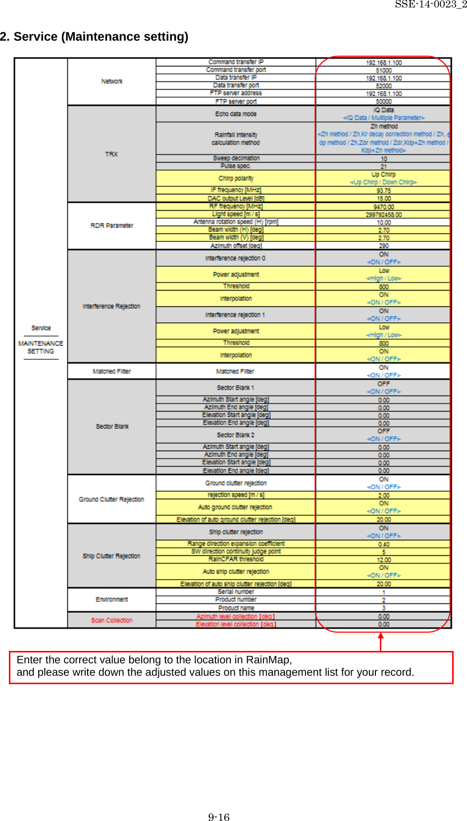
![SSE-14-0023_2 9-5 9.3.2. Service Press [Ctrl] + [Alt] and click [Setting] simultaneously to indicate service menu. Service menu has two types: 1. Maintenance setting: Regular menu for maintenance service engineer. 2. Factory setting: Adjust the setting of installed station use only for installation engineer. Notice: Follow the management list to setup all values. 1) Network Command transfer IP To setup the IP address of command transfer. ♦ Constant value: 192.168.1.101 Command transfer port To setup the port number of command transfer. ♦ Constant value: 51000 Data transfer IP To setup the IP address of data transfer. ♦ Constant value: 192.168.1.101 Data transfer port To setup the port number of data transfer. ♦ Constant value: 52000 FTP server address To setup the IP address of FTP server. ♦ Constant value: 192.168.1.100 FTP server port To setup the port number of FTP server. ♦ Constant value: 50000 2) TRX Echo data mode To select Echo data mode. - IQ Data: Use amplitude of Horizontal wave only. - Multiple Parameter: Use all information of reflected wave such as H/V amplitude and phase. Rainfall intensity calculation method To select a calculation method of Rainfall intensity calculation. ・ Zh method: Use horizontal amplitude information only. ・ Zh,Kr Attenuation correction method: Zh is calculated from the value that corrected rain attenuation by the amplitude. ・ Zh, φ dp method: Zh is calculated from the value that corrected rain attenuation by the φ dp. ・ Zh, Zdr method: Calculated from Zh and Zdr. ・ Zdr, Kdp+Zh method: Add into Zh after calculated from Kdp and Zdr. ・ Kdp+Zh: Use complex information, amplitude, and phase. Sweep decimation To setup a number of decimation. Size of transfer data. It uses the setting table when to determine a factor. Pulse spec. To setup a pulse number. Refer to the setting table as details of pulse settings.](https://usermanual.wiki/Furuno-USA/9ZWWR2100.User-Manual-III/User-Guide-2470825-Page-5.png)
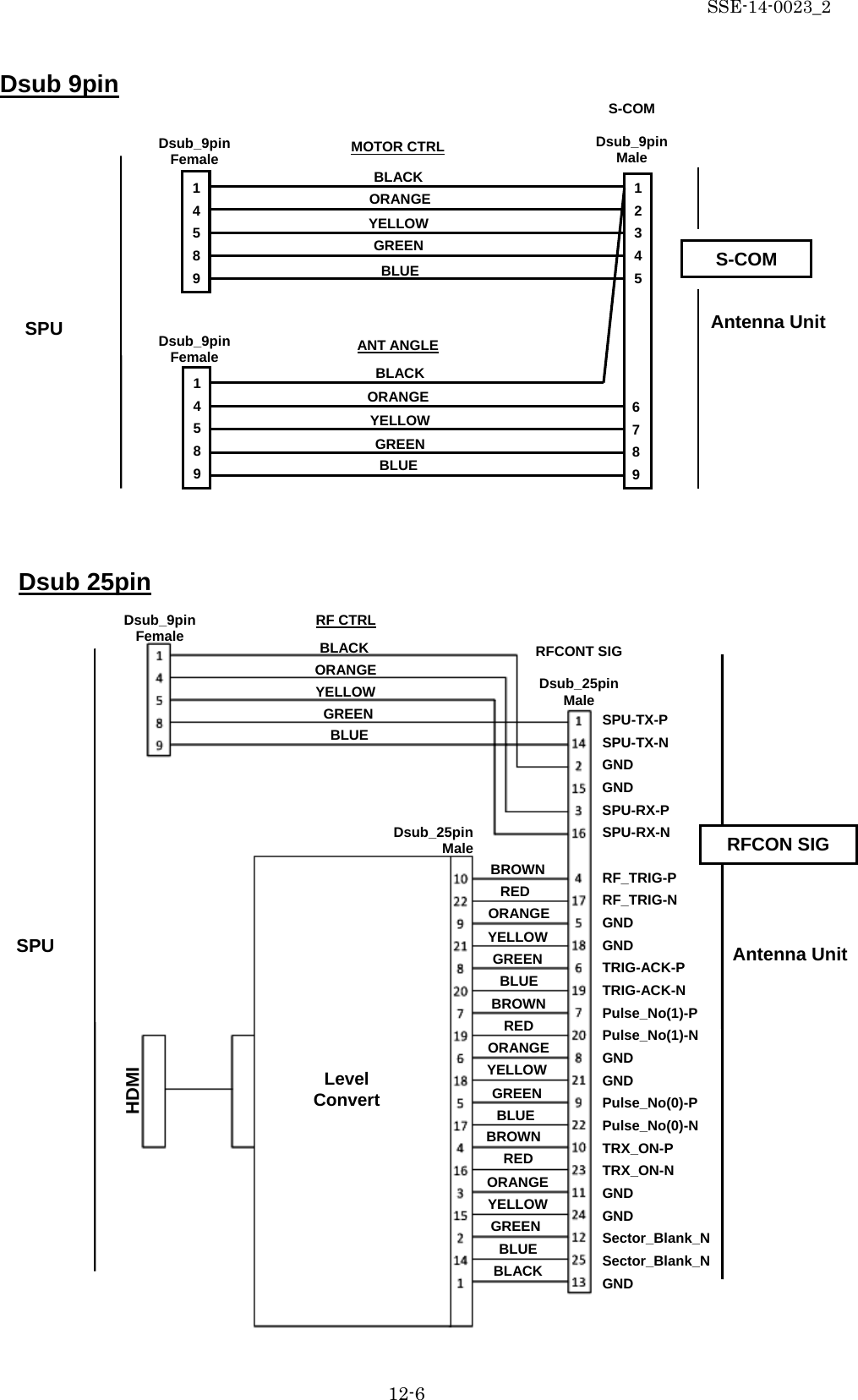
![SSE-14-0023_2 9-6 Chirp polarity (*It will indicate during factory setting) To select frequency shift direction. Up Charp: Sweep frequency to upward. Down Charp: Sweep frequency to downward. IF frequency [MHz] (*It will indicate during factory setting) To setup an IF (Intermediate Frequency) signal frequency. DAC output Level [dB] (*It will indicate during factory setting) To setup an amplitude of transmission signal output from SPU. 3) RDR Parameter RF frequency [MHz] (*It will indicate during factory setting) To setup a carrier frequency of transmitting signal. Light speed [m/s] (*It will indicate during factory setting) To setup a propagation speed of radio wave. Antenna rotation speed (H) [rpm] To setup a horizontal rotation speed of antenna. Beam width (H) [deg] (*It will indicate during factory setting) To setup an angle (Beam width) that -3dB beam width of antenna in horizontal polarization. Beam width (V) [deg] (*It will indicate during factory setting) To setup an angle (Beam width) that -3dB beam width of antenna in vertical polarization Azimuth offset (*It will indicate during factory setting) To setup an azimuth offset angle from origin to north. 4) Interference Rejection Interference rejection 0 - 1 Turn On or OFF an interference rejection function from other radar. Power adjustment (*It will indicate during factory setting) To select High or Low to adjust the power of IR0 -1. Threshold (*It will indicate during factory setting) To setup a threshold of judging interference wave. Interpolation (*It will indicate during factory setting) Turn On or OFF an interpolation. It indicates only when Factory setting is on It indicates only when Factory setting is on](https://usermanual.wiki/Furuno-USA/9ZWWR2100.User-Manual-III/User-Guide-2470825-Page-6.png)
![SSE-14-0023_2 9-7 5) Matched Filter Matched Filter Turn “ON” when to use QON and VON. This is a setting of receiving digital filter. 6) Sector Blank Sector Blank 1 -2 Turn ON or OFF a setting of transmission prohibited area. (Setup a rectangular solid angle area of Azimuth and Elevation) Azimuth Start angle [deg] To setup a starting angle point of azimuth direction. Starting point of azimuth is 0 degree on this unit. Follow a clockwise direction. Azimuth End angle [deg] To setup an ending angle point of azimuth direction. Elevation Start angle [deg] To setup a starting elevation angle. Horizontal direction is 0 degree. Follow a zenithal direction. Elevation End angle [deg] To setup an ending angle point of elevation. 7) Ground Clutter Rejection Ground clutter rejection Turn ON or OFF a judgment to remove ground clutter as a target if moving speed is lower than setting speed. Rejection speed [m/s] (*It will indicate during factory setting) To setup a removal speed (upper limit) of judging ground clutter. Auto ground clutter rejection (*It will indicate during factory setting) Turn ON or OFF an auto ground clutter rejection. Turn it “OFF” if elevation is above setting value. Elevation of auto ground clutter rejection [deg] (*It will indicate during factory setting) To setup an angle of boundary elevation to turn off ground clutter rejection. It indicates only when Factory setting is on](https://usermanual.wiki/Furuno-USA/9ZWWR2100.User-Manual-III/User-Guide-2470825-Page-7.png)
![SSE-14-0023_2 9-8 8) Ship Clutter Rejection Ship clutter rejection Turn ON or OFF for determine whether a target is a ship and to eliminate. Range direction expansion coefficient (*It will indicate during factory setting) To setup a range to expand a ship and the data to judge in the range direction. SW direction continuity judge point (*It will indicate during factory setting) To setup a point to judge the continuity of the sweep direction RainCFAR threshold (*It will indicate during factory setting) To setup a threshold to judge as a ship. Auto ship clutter rejection (*It will indicate during factory setting) To setup a threshold to judge as a ship. Elevation of auto ship clutter rejection [deg] (*It will indicate during factory setting) To setup an angle of boundary elevation to turn off ship clutter rejection. 9) Environment Serial number Enter the serial number. Product number Enter the product number. Product name Enter the product name. 10) Scan Collection Azimuth level collection [deg] To setup an azimuth offset from initial position. Parameters affect to elevation angle calibration. It adjusts the offset of magnet sensor by elevation calibration. Elevation level collection [deg] To setup an elevation offset from horizontal level. Measure the elevation angle after antenna initialization and set a field. It indicates only when Factory setting is on](https://usermanual.wiki/Furuno-USA/9ZWWR2100.User-Manual-III/User-Guide-2470825-Page-8.png)
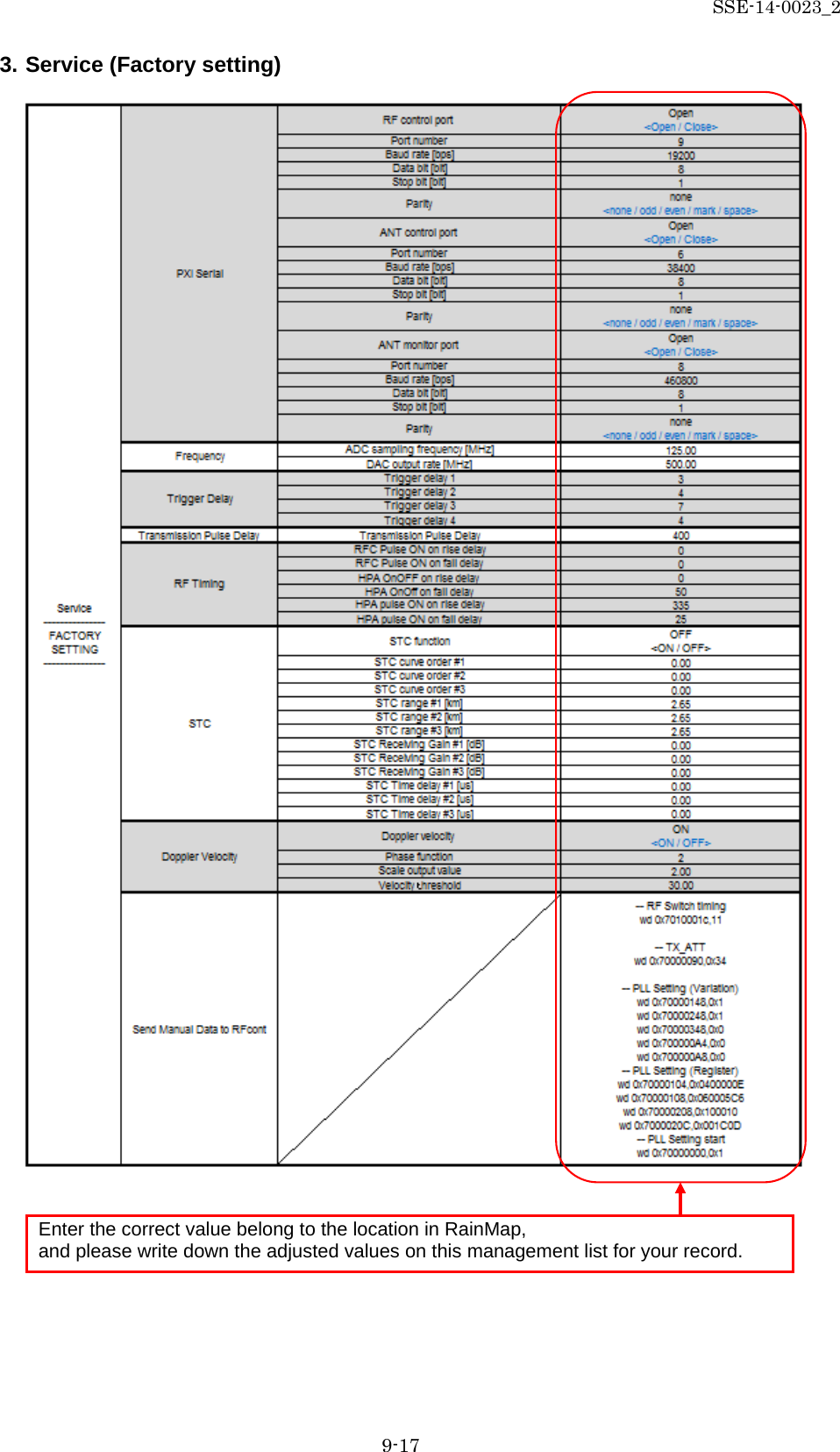
![SSE-14-0023_2 9-9 9.3.3. Factory setting 1. Click “Setting” + [Ctrl] + [Alt] simultaneously to Indicate the equipment setting of Service menu. 2. [Factory setting] button will indicate on the right side menu when clicked [Service] in the left menu. 3. Pop-up menu of [Enter password of Factory setting] will indicate when clicked [Factory setting] button. 4. Factory setting menu will indicate below Service menu after entered the password 1) PXI Serial RF control port To Open or Close RF control port. Port number To setup a port number. Baud rate [bps] To setup a baud rate. Data bit [bit] To setup a data bit. Stop bit [bit] To setup a stop bit. Parity To select the setting. (none / odd / even / mark / space) Enter Password: rainmap ANT control port To Open or Close ANT control port. ANT monitor port To Open or Close ANT monitor port.](https://usermanual.wiki/Furuno-USA/9ZWWR2100.User-Manual-III/User-Guide-2470825-Page-9.png)
![SSE-14-0023_2 9-10 2) Frequency ADC sampling frequency [MHz] To setup a sampling frequency of AD converter. DAC output rate [MHz] To setup an output rate of DA converter. 3) Trigger delay Trigger delay 1 - 4 To setup a trigger delay timing #1 - #4 of transmission signal. 4) Transmission Pulse Delay Transmission Pulse Delay To setup a clock frequency (normally 125MHz) of transmission pulse delay. 5) RF Timing RFC pulse ON on rise delay To setup a clock frequency (normally 125MHz) of RFC pulse on rise delay. It turns “OFF” a pulse of LNA bias during a period of transmission. RF_trig rise against delay time. RFC pulse ON on fall delay To setup a clock frequency (normally 125MHz) of RFC pulse on fall delay. It turns “OFF” a pulse of LNA bias during a period of transmission. RF_trig fall against delay time. HPA OnOff on rise delay Control signal (the power is “OFF” during HPA receiving period) of HPA power switch (drain voltage) could setup a rise delay time for RF_Trig. HPA OnOff on fall delay Control signal (the power is “OFF” during HPA receiving period) of HPA power switch (drain voltage) could setup a fall delay time for RF_Trig. HPA pulse ON on rise delay Control signal (the power is “OFF” during HPA receiving period) of HPA power switch (pulse voltage) could setup a rise delay time for RF_Trig.](https://usermanual.wiki/Furuno-USA/9ZWWR2100.User-Manual-III/User-Guide-2470825-Page-10.png)
![SSE-14-0023_2 9-11 HPA pulse ON on fall delay Control signal (the power is “OFF” during HPA receiving period) of HPA power switch (pulse voltage) could setup a fall delay time for RF_Trig. 6) STC STC function Turn ON or OFF a STC (Sensitivity Time Control) data transmission. STC curve order #1 - 3 To setup a degree of 1 - 3 STC curve order area. STC range #1 [km] To setup a distance of 1st and 2nd STC area. STC range #2 [km] To setup a distance of 2nd and 3rd STC area. STC range # 3 [km] To setup the last distance of 3rd STC area. STC Receiving Gain #1 – 3 [dB] To setup a value of STC receiving gain #1 - 3. STC Time delay #1 – 3 [us] To setup a value of STC time delay #1 – 3. 7) Doppler Velocity Doppler velocity Turn ON or OFF a doppler velocity calculation. Phase function To setup a correlation coefficient when calculate doppler velocity. Scale output value For spare. Velocity threshold For spare. 8) Send Manual Data to RFcont Input manual setting data](https://usermanual.wiki/Furuno-USA/9ZWWR2100.User-Manual-III/User-Guide-2470825-Page-11.png)
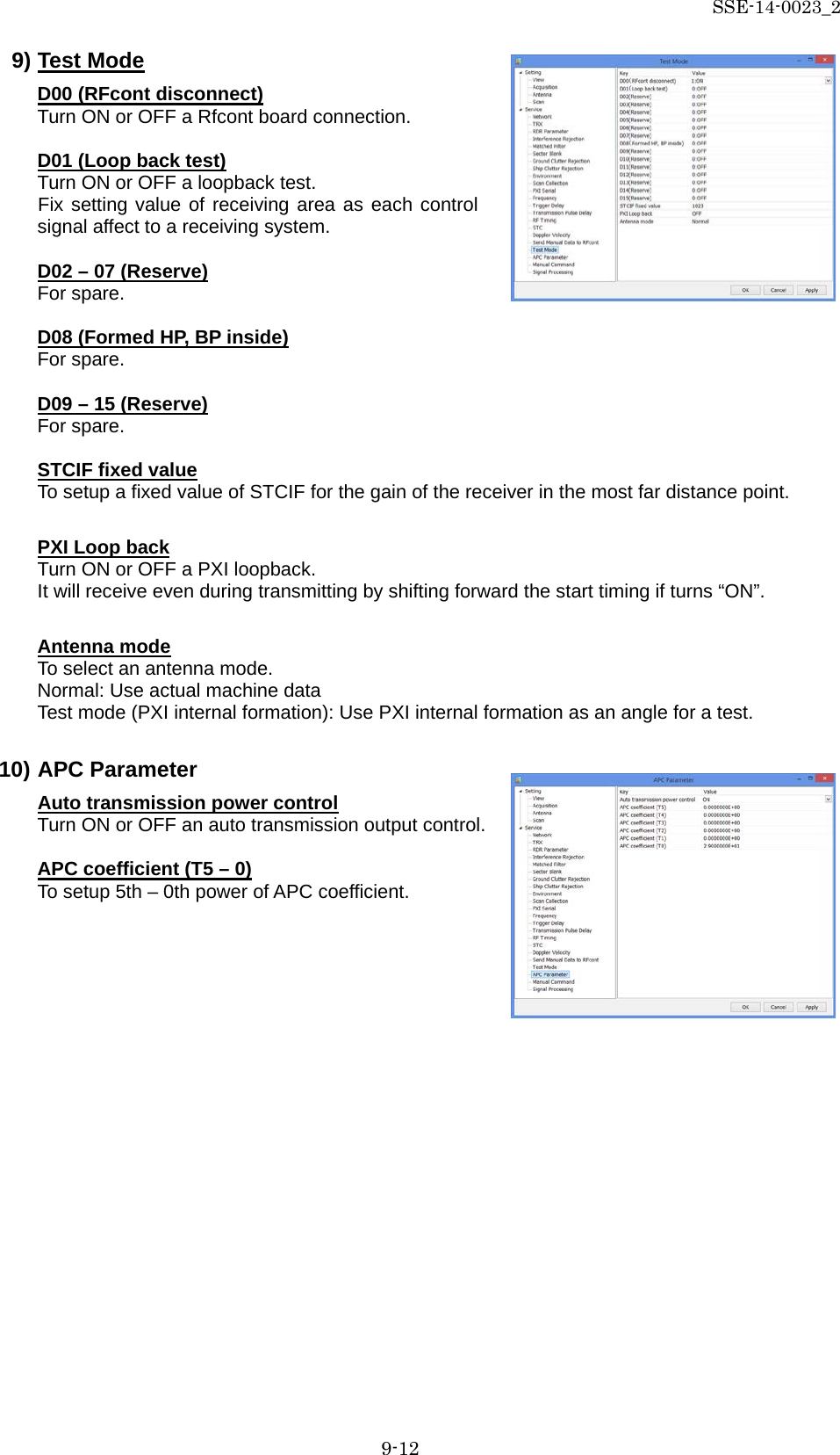
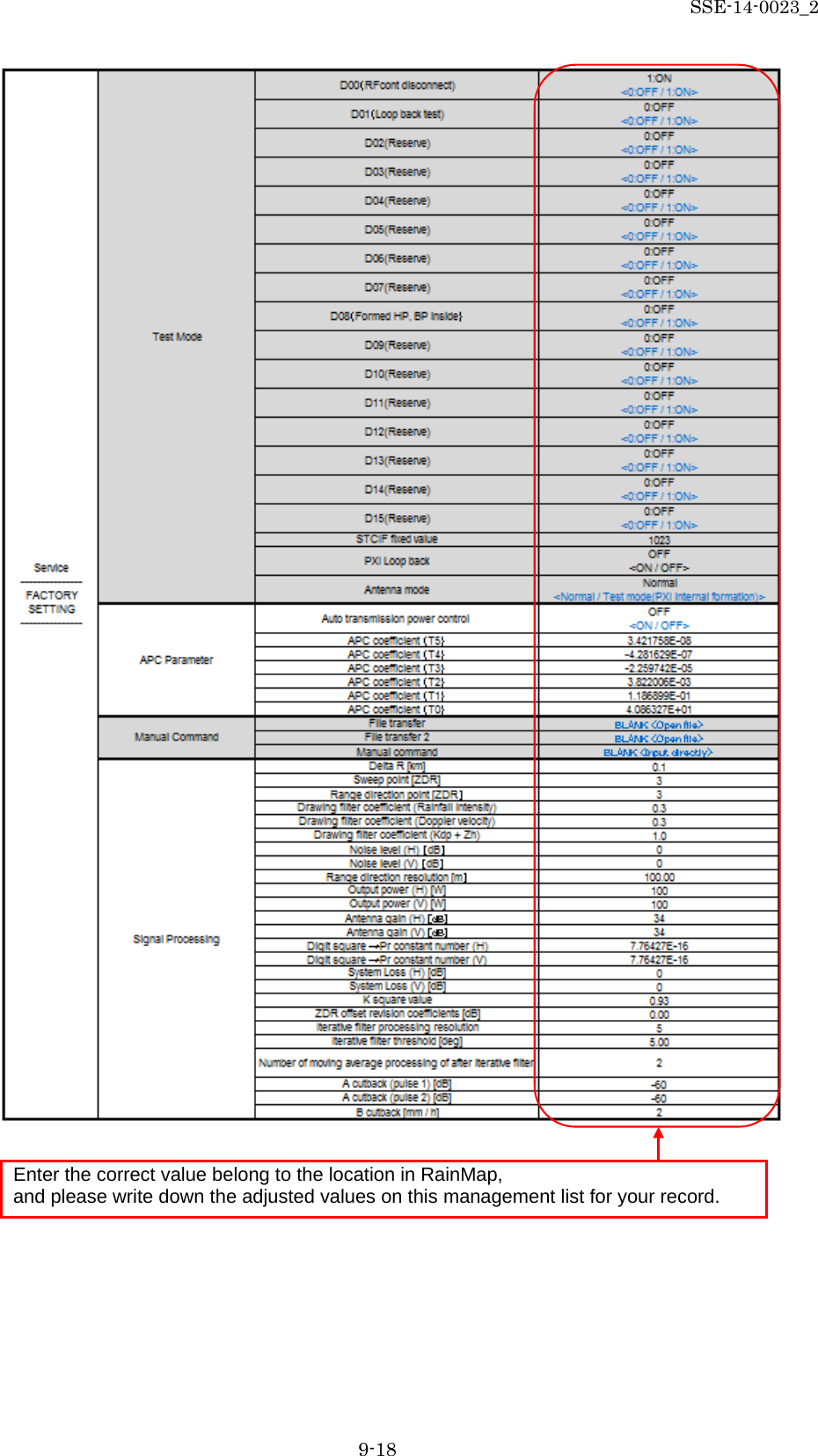
![SSE-14-0023_2 9-13 11) Manual Command It has to select [All Files(*.*)] at extension instead of [*.txt] to open [*.conf] file. Filter transfer Open parameter file which is necessary for compact weather radar. The setup value is for compact weather radar. However it must have to turn OFF on Ground Clutter Rejection for using selected file because it is not for regular operation. File transfer 1 FAR3000SSD_kisyou_No_32_P0N_GCR_OFF_yyyymmdd.conf (yyyymmdd means Year/Month/Date) File transfer 2 FAR3000SSD_kisyou_RFCONT_SNxxxx_ yyyymmdd.conf (xxxx means a serial number of radar, yyyymmdd means Year/Month/Date) Manual command To setup radar command directory 12) Signal Processing Delta R [km] To setup a delta range that calculation of Kdp. Sweep point [ZDR] To setup a sweep point that calculate Zdr. Range direction point [ZDR] To setup a range direction point that calculate Zdr. Drawing filter coefficient (Rainfall intensity) To setup a value of drawing filter coefficient (Rainfall intensity). It convert indication data into LPF in the azimuth direction and improve the visibility of the echo. Drawing filter coefficient (Doppler speed) To setup a value of drawing filter coefficient (Doppler speed). It convert indication data into LPF in the azimuth direction and improve the visibility of the echo. Drawing filter coefficient (Kdp + Zh) To setup a value of drawing filter coefficient (Kdp + Zh). It convert indication data into LPF in the azimuth direction and improve the visibility of the echo. Noise level (H) [dB] To setup a noise level (Horizontal). Noise level (V) [dB] To setup a noise level (Vertical). Range direction resolution [m] To setup a range direction of resolution. Output power (H) [W] To setup an output power of transmission (Horizontal). Output power (V) [W] To setup an output power of transmission (Vertical). Antenna gain (H) [dB] To setup a value of antenna gain (Horizontal). Antenna gain (V) [dB] To setup a value of antenna gain (Vertical).](https://usermanual.wiki/Furuno-USA/9ZWWR2100.User-Manual-III/User-Guide-2470825-Page-13.png)
![SSE-14-0023_2 9-14 Digital square -> Pr constant number (H) To setup a constant number to convert it into the electricity (Pr) of the antenna edge from a digital data level sampled in ADC (Horizontal polarized wave). Digital square -> Pr constant number (V) To setup a constant number to convert it into the electricity (Pr) of the antenna edge from a digital data level sampled in ADC (Vertical polarized wave). System Loss (H) [dB] To setup a value of system loss (Horizontal). System Loss (V) [dB] To setup a value of system loss (Vertical). K square value To setup a K square value (Typical weather radar multiplier). ZDR offset revision coefficient [dB] To setup a value of Zdr to revise amplitude deviation of horizontal and vertical. Iterative filter processing resolution To setup a number of iterative filter processing for φdp calculation. Iterative filter threshold [deg] To setup an angle of iterative filter threshold for φdp calculation. Number of moving average processing of after iterative filter To setup a number of moving average processing of after iterative filter for φdp calculation. A cutback (pulse 1 -2) [dB] To setup a threshold value for removing (not to indicate on a screen) noise (Pulse 1 - 2). B cutback [mm/h] To setup a value of B cutback for removing (not to indicate on a screen) noise. Notice: Reboot RainMap for saving data which is in “ini” file.](https://usermanual.wiki/Furuno-USA/9ZWWR2100.User-Manual-III/User-Guide-2470825-Page-14.png)
![SSE-14-0023_2 9-19 9.4. Radar Operation 1) Turn on the power of Display Unit (PC) 2) Software will start automatically. 3) Click [Connect] button to start radar operation. [Connect] will be indicated in the left bottom. 4) Click [TX] button to start observation. Radar echo will indicate with rotate scanning line after the message of [Initializing] on the screen. 5) Click [STBY] button to stop observation. 6) Click [Disconnect] button to stop connecting with radar. Notice) The following command could not operate without connecting radar: - Radar operation (Connect/Disconnect, TX/STBY) - Screen capture 9.5. Help - Version: To indicate the version information of software . 9.6. Emergency Stop - Stop motor: To stop motor of radar and TX at once. This white line is a scanning line](https://usermanual.wiki/Furuno-USA/9ZWWR2100.User-Manual-III/User-Guide-2470825-Page-19.png)
![SSE-14-0023_2 9-20 9.7. Adjustment of Azimuth The real geographical feature and azimuth are different with the initial echo indication, therefore it has to make an adjustment. Notice: Ground Clutter Rejection must be “OFF” during this operation. 1) Use a map of geographical features around the place installed the radar unit. (e.g. Google map) 2) Setup “Range [km]”, “Data Type”, in [View] setting menu of RainMap. 3) Setup “PPI elevation” in [Scan] setting menu of RainMap. 4) Setup “Azimuth Offset” in [RDR Parameter] setting menu of RainMap. Location (Date) <Image screen> At first, to setup an Antenna elevation a little higher to 5 degree. Next, to make only the higher mountain that can be seen by echo instead of surrounding buildings . To inferred a correct echo indicate azimuth from characteristic echo and a location of mountain map. Zh echo Elevation 5 degree Range 10km No.32 P0N transfer GCR OFF](https://usermanual.wiki/Furuno-USA/9ZWWR2100.User-Manual-III/User-Guide-2470825-Page-20.png)
![SSE-14-0023_2 9-21 5) Click [STBY] from [Radar operation] to Stop TRX. 6) Indicate a map and RainMap on a screen (or use other PC to see a map). 7) To grasp a characteristic geographical feature (check some top of the mountains’ line form, distance, and relative bearing) from map. 8) To transfer the wavelength to a higher direction for not to receive an echo from lower building or structure after setting elevation to 5 degrees (It could be 3 to 7 degrees in some case) in RainMap. 9) To setup a distance that could be easier to confirm a geographical feature of “3)” to “Range [km]” in [View] setting menu of RainMap. 10) To setup “Reflective Intensity [H]” at “DataType” in [View] setting menu of RainMap. 11) To confirm an echo after starting [TX] from [Radar operation]. Purple part means a strong echo that might be came from a mountain. 12) Click [STBY] from [Radar operation] before make any change for setting. Then, to change an angle of “Azimuth Offset” in [RDR Parameter] service menu of RainMap by comparing a shape of echo with “3)” and “7)”. Echo indication will be rotated to clockwise if entered a large value at “Azimuth Offset”. (Available range: -360 to 360) 13) Repeat a step “7)” to “8)” until an echo accords with a geographic feature 14) Click [STBY] from [Radar operation] after finished “9)”. 15) To set 0 degree at [Elevation] in [View] setting menu of RainMap. 16) To set a distance that suitable for the field at “Range [km]” in [View] setting menu of RainMap. 17) To select “Rainfall Intensity” at [DataType] in [View] setting menu of RainMap. 18) Finish a setting 9.8. Total operation test Click [TRX] from [Radar operation] to confirm that a structure of a circumference is indicated. 1) To change a file which had changed at “11) Manual command” setting menu of RainMap. It changes only to [File transfer]. FAR3000SSD_kisyou_No_32_P0N_yyyymmdd.conf (yyyymmdd means Year/Month/Date) 2) To confirm that an echo appears when started [TRX] from [Radar operation]. 3) Click [STBY] from [Radar operation] to stop TRX. 4) To follow the same process of “1)” to change a file. FAR3000SSD_kisyou_No_29_Q0N_yyyymmdd.conf (yyyymmdd means Year/Month/Date) 5) To confirm that an echo appears when started [TRX] from [Radar operation]. 6) Click [STBY] from [Radar operation] to stop TRX. 7) To follow the same process of “1)” to change a file. FAR3000SSD_kisyou_No_36_P0N+Q0N_PPI_yyyymmdd.conf (yyyymmdd means Year/Month/Date). 8) Click [TRX] from [Radar operation] to confirm that an indication would shift an echo when a scanning line rotates in every round. 9) Click [STBY] from [Radar operation] to stop TRX. 10) To select the best file at last by the local situation. Or to change the necessary setting like as elevation to finish it. Notice: To keep the setting according to the local situation at last. Make sure to turn ON/OFF the power of radome and /or PC, and TRX/STBY the radar operation.](https://usermanual.wiki/Furuno-USA/9ZWWR2100.User-Manual-III/User-Guide-2470825-Page-21.png)
![SSE-14-0023_2 10-2 10. Menu Tree RainMap Menu [File] Menu [File Play.] Menu [Snapshot] Menu [Exit] Menu [Disp] Menu [Disp select] Menu [2D] Menu [3D] Menu [Sub echo] Menu [Information Indication] Menu [Setting] Input [View] Input [Acquisition] Input [Antenna] Input [Scan] Menu [Radar Operation] Menu [Connect] Menu [Disconnect] Menu [TX] Menu [STBY] Menu [Help] Menu [Version] Menu [Emergency Stop] Menu [Stop motor]](https://usermanual.wiki/Furuno-USA/9ZWWR2100.User-Manual-III/User-Guide-2470825-Page-22.png)
![SSE-14-0023_2 10-3 RainPlay Menu [File] Menu [File Play] Menu [Print] Menu [Main screen] Menu [SRHI screen] Menu [Exit] Menu [Setting] Input [Scale] Input [Azimuth Offset] Menu [Disp] Menu [Select] Menu [View] Input [Rain] Input [Zhh] Input [V] Input [Zdr] Input [Kdp] Input [φdp] Input [phv] Input [W] Menu [Transparency] Input [0%] Input [25%] Input [50%] Input [75%] Input [100%] Menu [Map] Menu [SRHI screen] Menu [Clear] Menu [Play] Menu [Start] Menu [Stop] Menu [Pause] Menu [Fast Forward] Menu [Rewind] Menu [Time Display] Menu [Print screen ] Menu [Main screen] Menu [SRHI screen]](https://usermanual.wiki/Furuno-USA/9ZWWR2100.User-Manual-III/User-Guide-2470825-Page-23.png)