Furuno USA 9ZWRTR104 Transceiver for Radar Sensor DRS4DL User Manual
Furuno USA Inc Transceiver for Radar Sensor DRS4DL
Contents
- 1. User Manual I
- 2. User Manual II Part 1
- 3. User Manual II Part 2
- 4. User Manual II Part 3
- 5. User Manual II Part 4
- 6. User Manual II Part 5
- 7. User Manual II Part 6
- 8. User Manual II Part 7
- 9. User Manual II Part 8
- 10. User Manual II Part 9
- 11. User Manual II Part 10
- 12. User Manual II Part 11
- 13. User Manual II Part 12
User Manual II Part 7
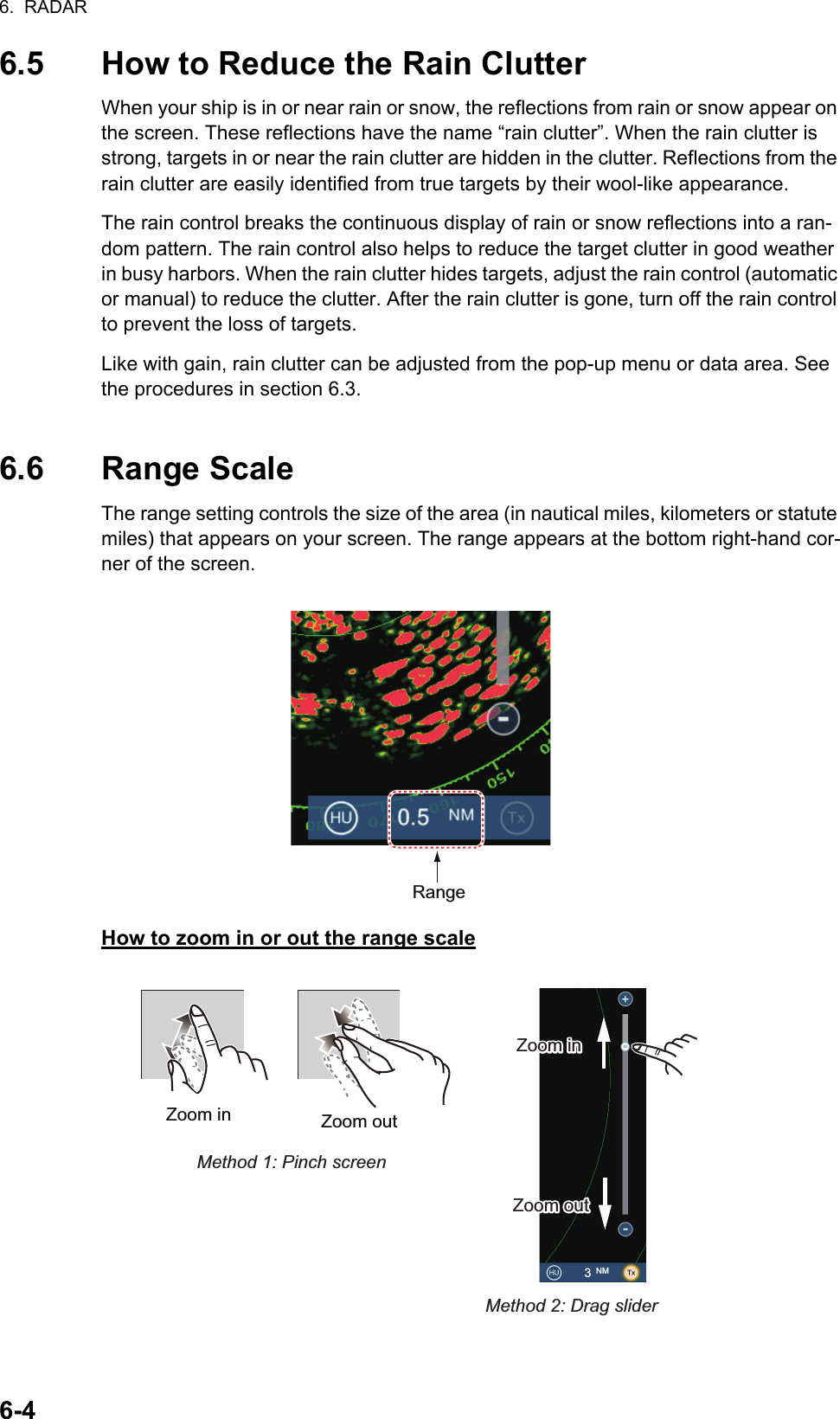
![6. RADAR6-56.7 Orientation ModeThe orientation mode controls the relationship between your ship and all the other tar-gets.The heading data is required in the north-up mode. When the heading data is lost, the orientation mode automatically goes to head-up. Restore the compass signal to show the heading indication. Select the orientation mode again if necessary.To select an orientation mode, tap the orientation mode icon [HU] (or [NU], whichever is shown) icon at the bottom right corner of the screen to show [HU] (Head-up) or [NU] (North-up) as required.Head-upA display without azimuth stabilization in which the line that connects the center with the top of the screen indicates your heading. Targets are shown at their measured distances and in their directions rela-tive to your heading.North-upTargets are shown at their measured distances and their true (compass) directions from your ship. North is at the top of the screen. The heading line changes its direction according to your heading.Orienatation mode switchHUNUHead-up:North-up:Heading lineHeading line](https://usermanual.wiki/Furuno-USA/9ZWRTR104.User-Manual-II-Part-7/User-Guide-2522491-Page-2.png)
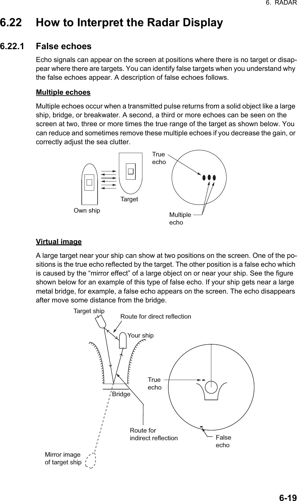
![6. RADAR6-66.8 How to Measure the Range and Bearing from Your Ship to a TargetYou can measure the range or bearing to a target by the following four methods.6.8.1 How to display the range ringsThe range rings are the concentric solid circles about your ship. Use the fixed range rings to get a rough estimate of the range to a target. To show or hide the range rings, open the [Layers] menu then turn [Radar Rings] on or off as required. To measure the range with the range rings, count the number of rings between the center of the screen and the target. Check the range ring interval and estimate the dis-tance of the echo from the inner edge of the nearest ring.6.8.2 How to set the number of the range rings to show1. Open the home screen, then tap [Settings] - [Radar].2. Tap [Rings Interval].3. Tap a number. [Automatic] automatically selects the number of rings according to the range scale.4. Tap the close button to finish.RangemeasurementBearingmeasurementFixed range rings Yes NoRuler Yes YesVRM (Variable Range Marker) Yes NoEBL (Electronic Bearing Line) No Yes](https://usermanual.wiki/Furuno-USA/9ZWRTR104.User-Manual-II-Part-7/User-Guide-2522491-Page-3.png)
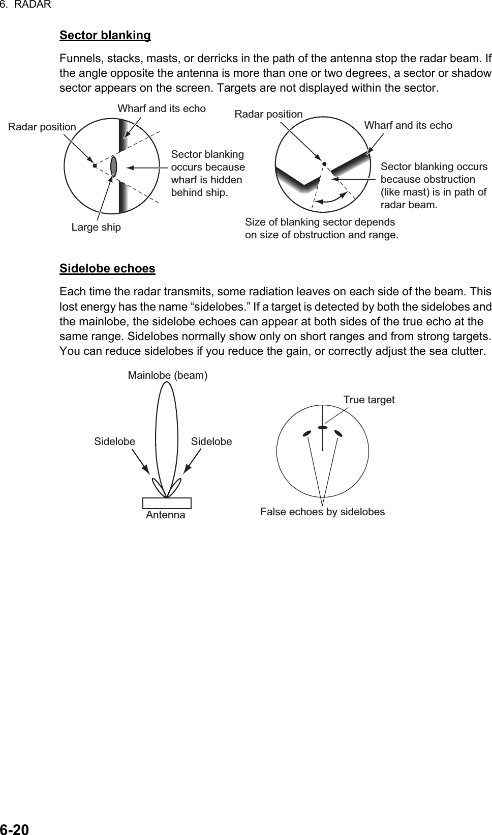
![6. RADAR6-76.8.3 How to select the range rings modeTo select the range rings mode, open the home screen, then tap [Settings] - [Radar]. Set [Bearing Scale Mode] and [Relative] or [True].Relative: Bearing scale is fixed and “0” is at the top of the screen.Boat icon010 2030405060708090100110120130140150160170180190200210220230240250260270280290300310320330340 350010203040 50 60 70 8090100110120130140150160170180190200210220230240250260270280290300310320330340350010 2030405060708090100110120130140150160170180190200210220230240250260270280290300310320330340 350010203040 50 60 70 8090100110120130140150160170180190200210220230240250260270280290300310320330340350North (“0”)Heading lineBearing scaleTrue: Bearing scale rotates according to the movement of your ship.Head-up modeNorth-up modeRelative: Bearing scale rotates according to the movement of your ship.True: Bearing scale is fixed and “0” is at the top of the screen.Boat iconBearing scaleHeading line](https://usermanual.wiki/Furuno-USA/9ZWRTR104.User-Manual-II-Part-7/User-Guide-2522491-Page-4.png)
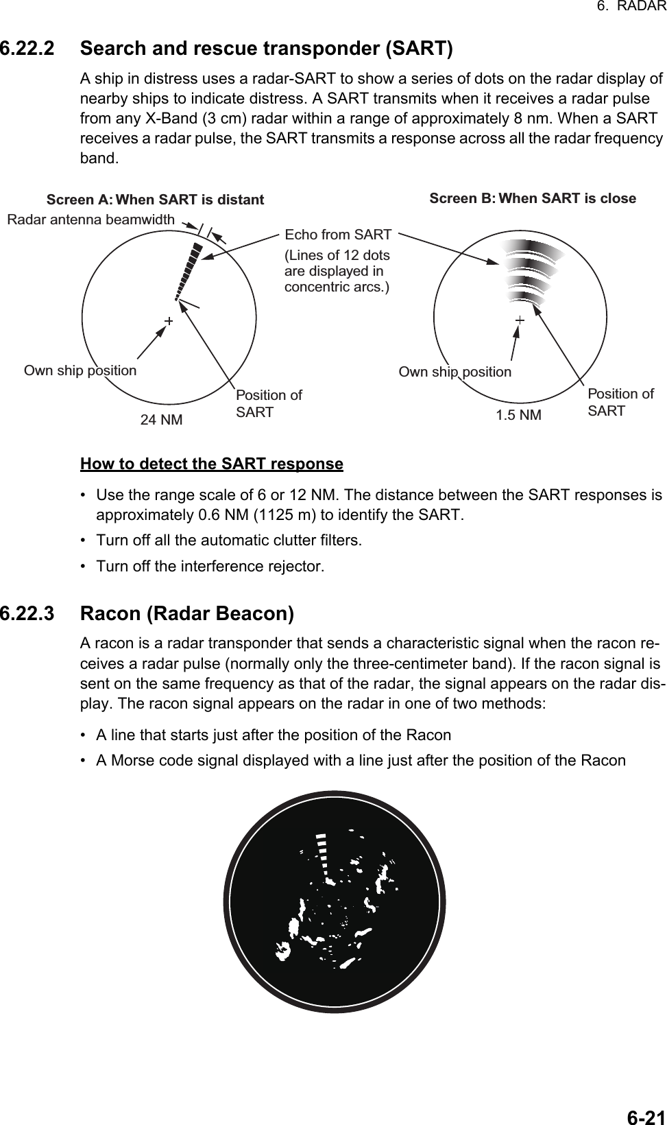
![6. RADAR6-86.8.4 How to measure the range and bearingTap an object to get the range and bearing. Read the range and bearing in the box.6.8.5 How to measure the range with the VRMThe VRM is a dashed ring so that you can identify the ring from the fixed range rings.Method 1: From the data areaOpen the data area. Tap the VRM indication in the [EBL/VRM] data box. Drag the VRM or slider to set the VRM. Tap [End VRM] to anchor the VRM and finish. The range to the VRM appears to the left of the slider bar and in the [EBL/VRM] data box.To clear the VRM, open the pop-up menu, the tap [EBL] and [Clear].ObjectRange and bearingto objectTaphere.ORDragsliderDragsliderTap [End VRM] to anchor VRM and exit.Drag VRMEBL/VRMdata boxDragVRMDragVRMRange to objectRange to objectRADARDATA ROUTE](https://usermanual.wiki/Furuno-USA/9ZWRTR104.User-Manual-II-Part-7/User-Guide-2522491-Page-5.png)
![6. RADAR6-9Method 2: From the pop-up menuTap the screen to show the pop-up menu, then tap [VRM]. Drag the VRM or slider to set the VRM. Tap [End VRM] to anchor the VRM and finish. The range to the VRM appears to the left of the slider bar.To clear the VRM, open the pop-up menu, the tap [VRM] and [Clear].DragsliderDragsliderORDrag VRMDragVRMDragVRMTap screen to show pop-up menu. Tap [VRM].Tap [Adjust].Tap [End VRM] to anchor VRM and exit.Range to objectRange to object](https://usermanual.wiki/Furuno-USA/9ZWRTR104.User-Manual-II-Part-7/User-Guide-2522491-Page-6.png)
![6. RADAR6-106.8.6 How to measure the bearing with the EBLMethod 1: From the data areaOpen the data area. Tap the EBL indication in the [EBL/VRM] data box. Drag the EBL or slider to set the EBL. Tap [End EBL] to anchor the EBL and finish. The range to the VRM appears to the left of the slider bar and in the [EBL/VRM] data box.To clear the EBL, open the pop-up menu, then tap [EBL] and [Clear].ORDragsliderDragsliderTap [End EBL] to anchor EBL and exit.Drag VRMEBL/VRMdata box84.7°84.7°Bearing to object84.7°DragEBLBearing to object84.7°End EBLEnd EBLEnd EBLRADARDATA ROUTE](https://usermanual.wiki/Furuno-USA/9ZWRTR104.User-Manual-II-Part-7/User-Guide-2522491-Page-7.png)
![6. RADAR6-11Method 2: From the pop-up menuTap the screen to show the pop-up menu, then tap [EBL]. Drag the EBL or slider to set the EBL. Tap [End EBL] to anchor the EBL and finish. The range to the EBL ap-pears to the left of the slider bar.To clear the EBL, open the pop-up menu, then tap [EBL] and [Clear].6.8.7 How to select the EBL referenceYou can select the EBL reference from [True] or [Relative]. [True] means the bearing is in reference to the north. [Relative] means the bearing is relative to the heading of your ship. True bearing requires a heading sensor.1. Open the home screen, then tap [Settings] - [Radar].2. Tap [EBL Reference].3. Tap [True] or [Relative].4. Tap the close button to finish.Tap screen to show pop-up menu. Tap [EBL].Tap [Adjust].ORDragsliderDragsliderTap [End EBL] to anchor EBL and exit.Drag VRM84.7°84.7°Bearing to object84.7°DragEBLBearing to object84.7°End EBLEnd EBLEnd EBL](https://usermanual.wiki/Furuno-USA/9ZWRTR104.User-Manual-II-Part-7/User-Guide-2522491-Page-8.png)
![6. RADAR6-126.9 How to Measure the Range and Bearing Between Two TargetsYou can measure the range and bearing between any two targets with the ruler.1. Open the slide-out menu then tap [Distance] to display the ruler, which has two drag-gable circles connected with a line.2. Drag the circles to set them on the objects for the measurement. The range and bearing between the objects, SOG and TTG appear at the top of the screen.3. Tap [Cancel Ruler] at the top right-hand corner of the screen to erase the ruler and the indication.6.10 How to Off-center the PictureYou can off-center your position to expand the view field without selecting a larger range scale. The position can be off-centered in the bow, stern, port or starboard di-rection, but not more than 75% of the range in use.Pan the radar display by dragging with a finger. To return your ship to the center of the screen, tap [Center Radar] at the top right-hand corner of the screen.Range BearingSpeed Over the Ground TTGStarting location2nd locationNormal picture Picture off-centered in stern direction304050607080901001101201301401502102202302402502602702802903003103203300102030405060708090100110250260270280290300310320330340350](https://usermanual.wiki/Furuno-USA/9ZWRTR104.User-Manual-II-Part-7/User-Guide-2522491-Page-9.png)
![6. RADAR6-136.11 Heading LineThe heading line indicates your heading in all orientation modes. This line connects between your position to the outer edge of the radar display. The line is at zero de-grees on the bearing scale in the head-up mode. The orientation of the line changes in the north-up mode with the movement of your ship. If it is hard to identify the echoes on the heading line, you can hide the heading line and range rings for a few seconds. Open the pop-up menu then tap [Hdg Ln Off] to show or hide the heading line.6.12 How to Reduce Radar InterferenceRadar interference can occur when your ship is near the radar of another ship that operates on the same fre-quency band with your radar. The interference shows on the screen in many bright dots. The dots can be ran-dom or in the shape of dotted lines that run from the center to the edge of the screen. You can identify the interference from the normal echoes, because the in-terference does not appear in the same location at the next rotation of the antenna.Turn off the interference rejector when there is no inter-ference to prevent the loss of weak targets.1. Tap the screen then tap [Radar Filters].2. Turn [Int Reject] on or off as required.6.13 Guard ZoneThe guard zone provides aural and visual alarms against targets (ships, islands, land-masses, etc.) that enter the area you set.6.13.1 How to set the guard zoneNote: You can not set the guard zone with the MCU-002. Use the touch operation to set the guard zone.1. Open the [Layers] menu.2. Turn on [Guard Zone 1] or [Guard Zone 2] as re-quired. A guard zone appears with a circle at each of its four corners.3. Drag the circles to set the guard zone.Note: To set a 360-degree guard zone, set the same bearing for all four circles.4. Tap [Done] at the top right-hand corner of the screen to complete the guard zone and erase the circles.If you need to readjust a guard zone, tap on a line of the guard zone to show the pop-up menu then tap [Resize]. Drag the circles to adjust the guard zone. Tap [Done] at top right corner to finish.](https://usermanual.wiki/Furuno-USA/9ZWRTR104.User-Manual-II-Part-7/User-Guide-2522491-Page-10.png)
![6. RADAR6-146.13.2 How to activate or deactivate the guard zone1. Tap on a line of the guard zone to show the pop-up menu. 2. Turn [Alarm] on or off as required. The alarm is active when the guard zone lines are solid and the lines are dashed when the alarm is deactivated.When a target enters an active zone, the aural alarm sounds (if active), the target flashes, and the message "TARGET ALARM" flashes in the status bar. Tap the status bar to silence the aural alarm and stop the flashing message. The message remains in the status bar and the target continues to flash until the target leaves the guard zone or the alarm is deactivated.You can mute the audio alarm by turning off [Alarm Sound] in the [Settings] - [Alarm] menu. (see paragraph 2.11.6).6.13.3 How to hide the guard zoneOpen the [Layers] menu and turn [Guard Zone 1] or [Guard Zone 2] off as required The guard zone is erased from the screen.6.14 WatchmanThe watchman feature transmits the radar for one minute at a specified time interval (5, 10 or 20 minutes) to monitor the guard zone. If a target is found in the guard zone, the watchman is canceled and the radar continues to transmit. This feature helps you watch for targets in the area you set when you do not continuously require the radar.1. Set a guard zone. See section 6.13. (Watchman does not operate unless a guard zone is active. Set Watchman when the radar is in transmit state.)2. Open the home screen, then tap [Settings] - [Radar].3. Tap [Watchman].4. Tap a watchman rest interval.5. Tap the close button to finish.6. On the radar display, tap the screen to show the pop-up menu. Turn [Watchman] on to activate the watchman function.1 min 1 minTX TXST-BY ST-BYWatchman starts5, 10 or 20 min5, 10 or 20 min](https://usermanual.wiki/Furuno-USA/9ZWRTR104.User-Manual-II-Part-7/User-Guide-2522491-Page-11.png)
![6. RADAR6-156.15 How to Show, Hide or Cancel an Active RouteYou can show, hide the active route on the radar display. Open the [Layers] menu then turn [Routes] on or off as required.To cancel route navigation, tap any part of the route then tap [Stop Nav] on the pop-up menu.6.16 How to Show or Hide the Own Ship IconYou can show or hide the boat icon on the radar display.1. Open the home screen, then tap [Settings] - [Radar].2. Turn [Own Ship Icon] on or off as required.3. Tap the close button to finish.6.17 Echo ColorEcho color is available in colors of green, yellow or multicolor.1. Open the home screen, then tap [Settings] - [Radar].2. Tap [Echo Color].3. Tap a color.4. Tap the close button to finish.40506070809010011012013014015016017018019020021022023024025026027028029030031032011234Go to pointGo to pointYour shipYour ship’s positions position](https://usermanual.wiki/Furuno-USA/9ZWRTR104.User-Manual-II-Part-7/User-Guide-2522491-Page-12.png)
![6. RADAR6-166.18 Background ColorYou can select the background color for daytime and nighttime operations.1. Open the home screen, then tap [Settings] - [Radar].2. Tap [Day Background Color] or [Night Background Color] menu.3. Tap a color.4. Tap the close button to finish.6.19 Radar Overlay Range LinkThe radar overlay range link automatically keeps the display range and radar range in sync. This feature helps you understand the relation between the radar and the chart. You can activate or deactivate this feature from the plotter display. See paragraph 3.2.3.[]Note: The radar picture can look “out of focus” on long ranges when the range link is active. This out of focus appearance does not indicate a problem, because it is a char-acteristic of the digital zoom.](https://usermanual.wiki/Furuno-USA/9ZWRTR104.User-Manual-II-Part-7/User-Guide-2522491-Page-13.png)
![6. RADAR6-176.20 Dual-Range DisplayThe dual-range display scans and displays two different radar ranges at the same time, with a single antenna. There is no time delay between the two pictures and you have separate control of each picture. This feature lets you keep a close watch on close-range targets while watching distant targets. To get the dual-range display, set dual-range displays on the home screen. See paragraph 1.7.1for the procedure. You can put the dual-range displays in the two-way and three-way split screens.The radar functions that are adjusted separately are as follows:*: The no.1 screen is independent of the no.2 screen when the no.2 screen is in stand-by. However, when the no.2 screen goes to transmit state, so does the no.1 screen.• Active route (show or hide) • Gain• Rain (rain clutter) • Sea (sea clutter)• Heading line and rings (hide temporarily) • AIS/DSC (show or hide)• Range • Range rings (show or hide)• Orientation mode (head-up or north-up) • Trail (clear to restart)• Auto sea mode ([Advanced] or [Coastal]) • Interference rejector• Transmission* (Can not set stand-by mode separately)Short range displayLong range displayTwo-way split Three-way splitNo.1 screenNo.2 screenNo.1 screenNo.2 screen No.1 screen No.2 screenNo.2 screenNo.1 screen](https://usermanual.wiki/Furuno-USA/9ZWRTR104.User-Manual-II-Part-7/User-Guide-2522491-Page-14.png)
![6. RADAR6-186.21 Radar MenuThis section provides the descriptions for the radar menu items not mentioned earlier.Radar Initial Setup[Antenna Rotation]: Starts or stop antenna rotation. For the serviceman. See the in-stallation manual.[Antenna Heading Align]: Compensates for error in positioning of the antenna unit at installation. See the installation manual for the adjustment procedure.[Main Bang Suppression]: Reduces main bang, the clutter appearing at the screen center. See the installation manual for the adjustment procedure.[Enable Sector Blanking]: Sets the area(s) where to prevent transmission. For ex-ample, set the area where an interfering object at the rear of the antenna would pro-duce a dead sector (area where no echoes appear) on the display. See the installation manual for the procedure.[Antenna Position] items ([Longitudinal (from bow)], [Lateral (-Port)]): Set the posi-tion of the radar antenna in relation to the bow and port.Other items[Antenna Height]: Set the height of the radar antenna above the waterline.[Auto Tuning]: Activate or deactivate auto tuning.[Tuning Source]: Selects the radar range for the adjustment, [Range 1] (long range), [Range 2] ((short range).[Manual Tuning]: Manually tune.[Radar Monitoring]: Show various voltage levels, and ARPA data. For the service-man.[ARPA Advanced Settings]: Sets ARPA parameters. For the installer, serviceman. Do not change the settings.[Set Hardware to Factory Default]: For the serviceman. No use for the user.[Reset Default Settings]: Restore default settings for items other than those in the [RADAR INITIAL SETUP] section.](https://usermanual.wiki/Furuno-USA/9ZWRTR104.User-Manual-II-Part-7/User-Guide-2522491-Page-15.png)
![6. RADAR6-226.23 ARPA OperationThe ARPA (Automatic Radar Plotting Aid) shows the movement of a maximum of 30 radar targets. The targets can be acquired manually or automatically. All 30 targets can be acquired manually when the ARPA acquisition area is not active. If the ARPA acquisition area is active, that total is equally divided between manual and auto acqui-sition.ARPA requires speed and heading data.6.23.1 How to show or hide the ARPA display1. Open the [Layers] menu. 2. Turn [ARPA Targets] on or off as required.WARNINGWARNINGCAUTIONCAUTIONNo one navigational aid should be relied upon for the safety of vessel and crew. The navigator has the responsibility to check all aids available to confirm position. Electronic aids are not a substitute for basic navigational principles and common sense.· This auto plotter automatically tracks an automatically or manually acquired radar target and calculates its course and speed, indicating them by a vector. Since the data generated by the auto plotter are based on what radar targets are selected, the radar must always be optimally tuned for use with the auto plotter, to ensure required targets will not be lost or unwanted targets such as sea returns and noise will not be acquired and tracked.· A target does not always mean a landmass, reef, ships or other surface vessels but can imply returns from sea surface and clutter. As the level of clutter changes with environment, the operator should properly adjust the Sea, Rain and Gain to be sure target echoes are not eliminated from the radar screen.The plotting accuracy and response of this auto plotter meets IMO standards. Tracking accuracy is affected by the following:· Tracking accuracy is affected by course change. One to two minutes is required to restore vectors to full accuracy after an abrupt course change. (The actual amount depends on gyrocompass specifications.)· The amount of tracking delay is inversely proportional to the relative speed of the target. Delay ranges from 15 - 30 seconds for high relative speed; 30 - 60 seconds for low relative speed.Display accuracy is affected by the following:· Echo intensity· Radar transmission pulsewidth· Radar bearing error· Gyrocompass error· Course change (your ship or target)](https://usermanual.wiki/Furuno-USA/9ZWRTR104.User-Manual-II-Part-7/User-Guide-2522491-Page-19.png)