Furuno USA 9ZWRTR101 Transceiver for Radar model FAR-1518/1528 User Manual

Furuno USA Inc Transceiver for Radar model FAR-1518/1528

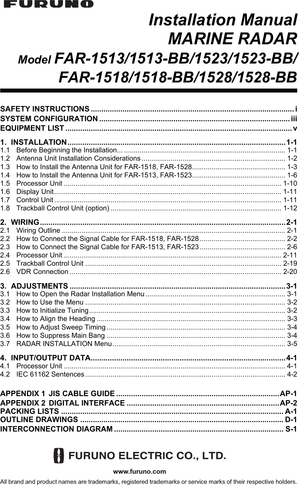
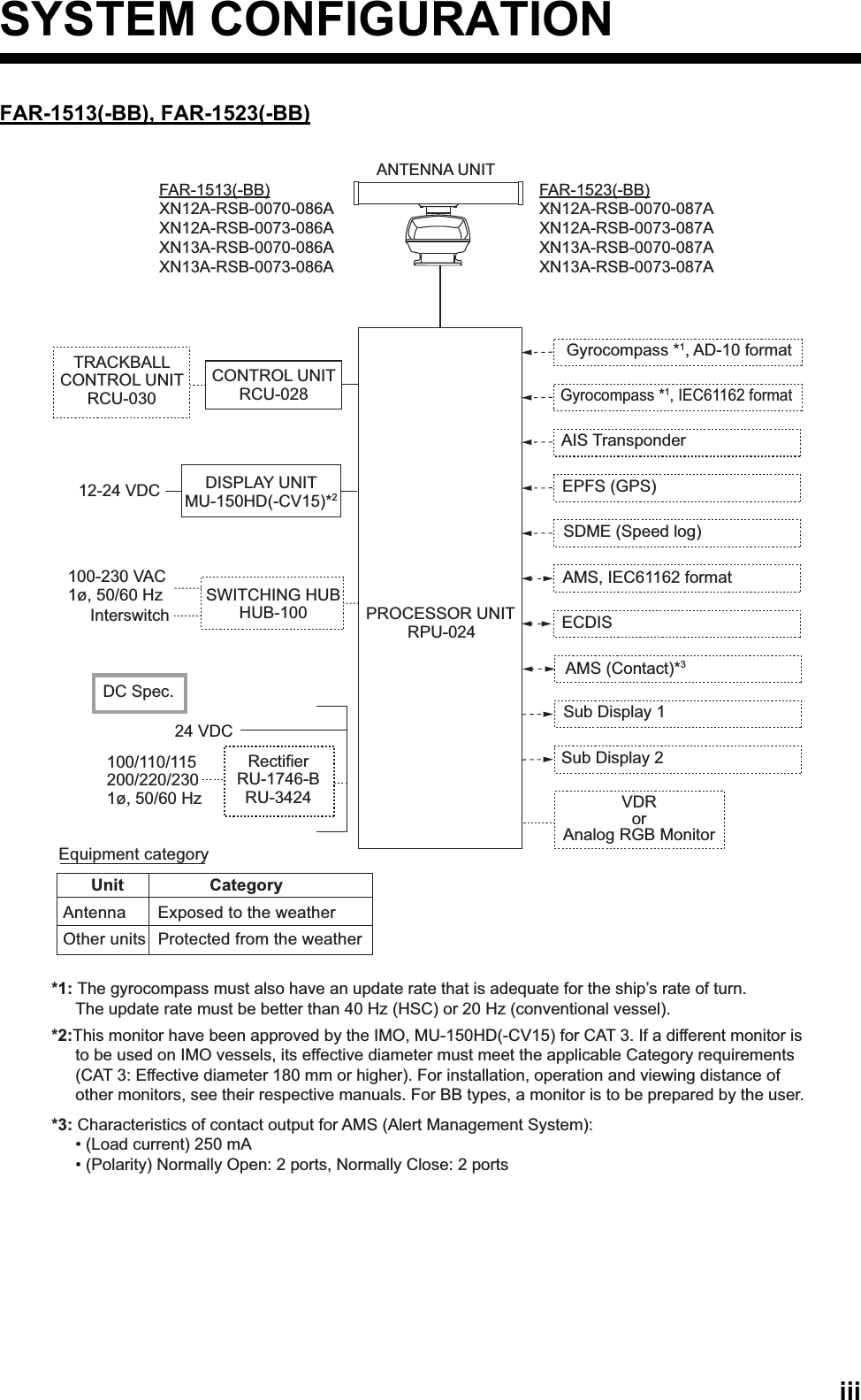
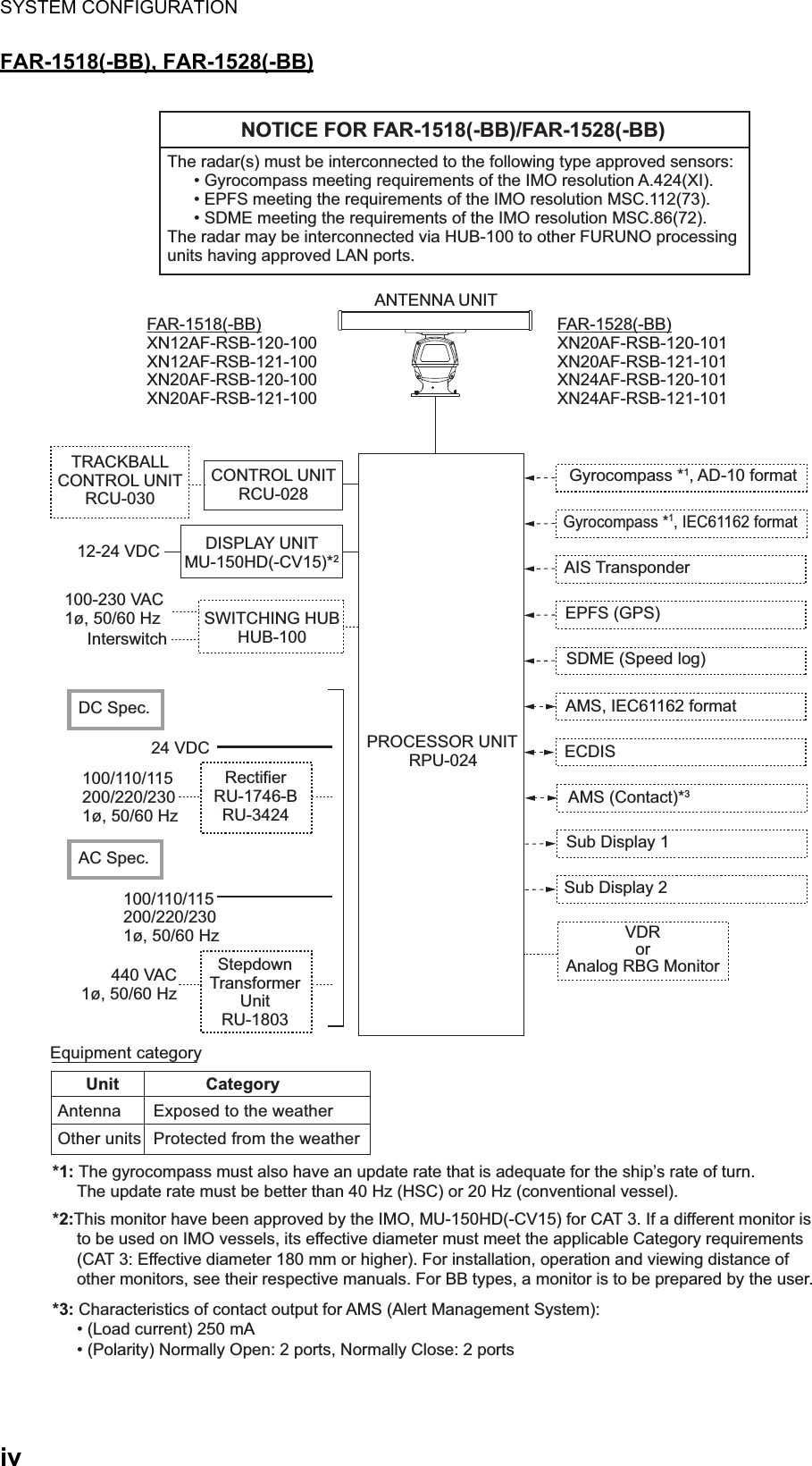
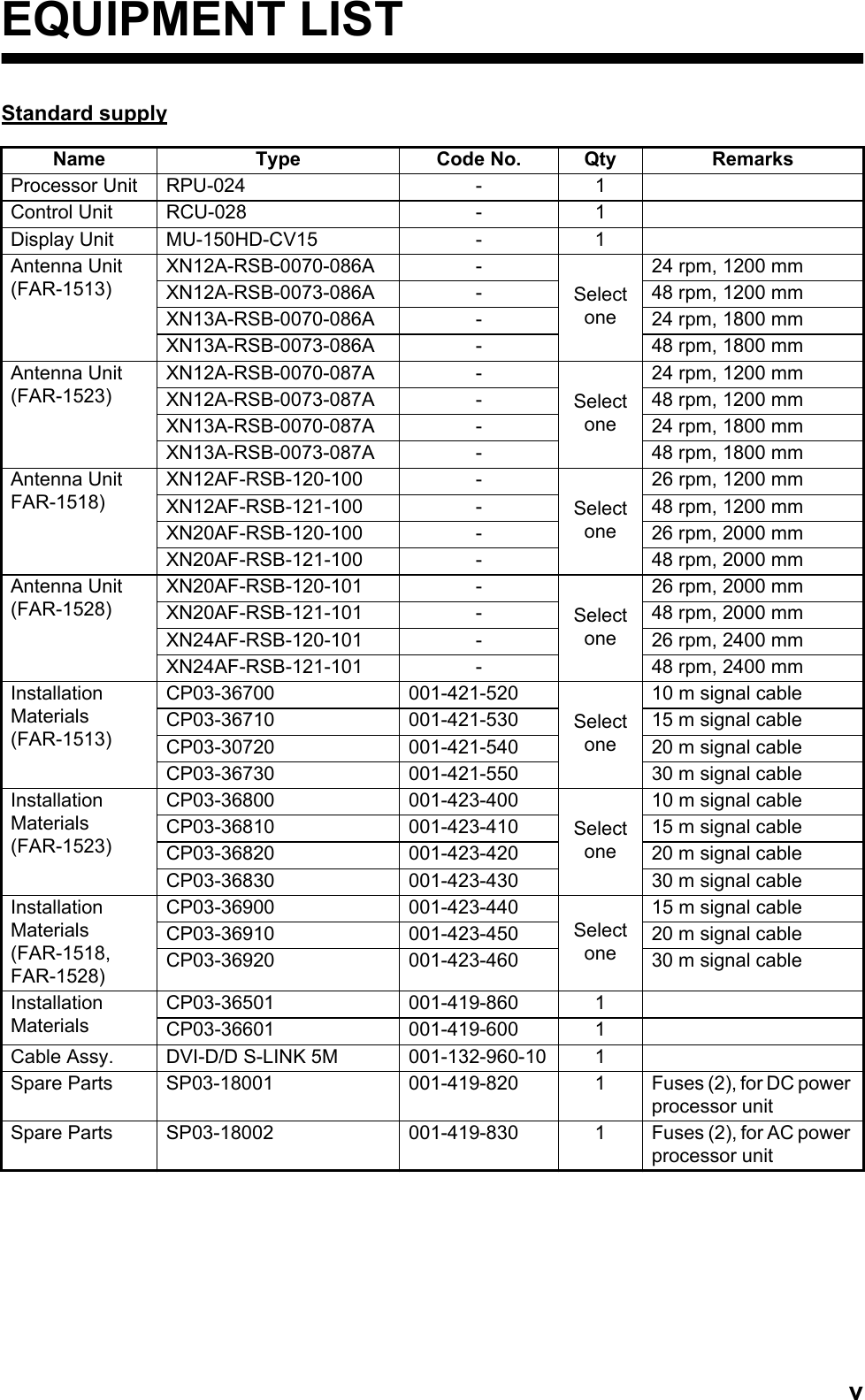
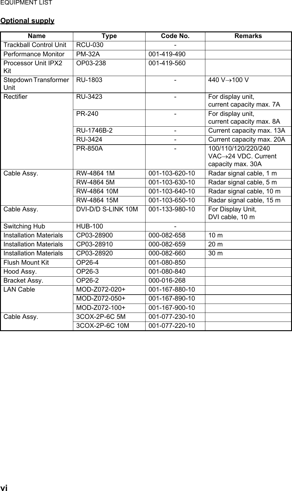
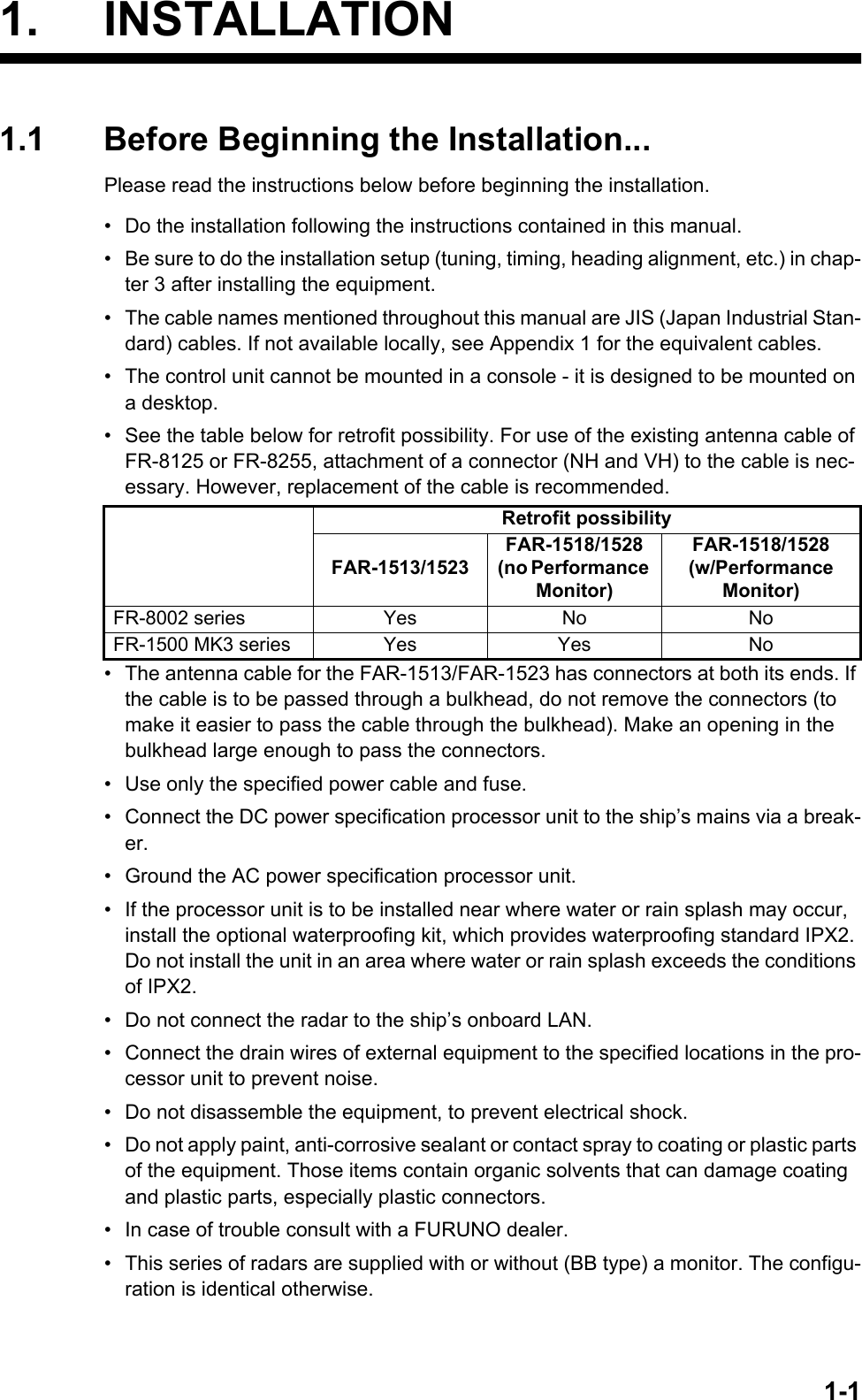
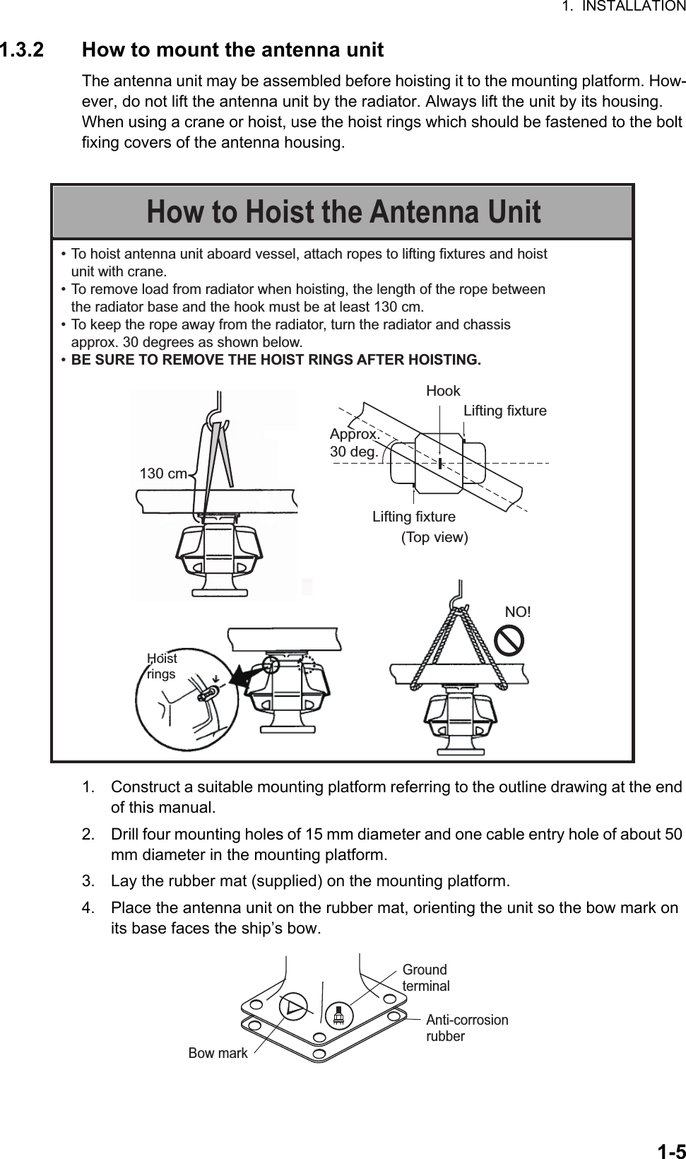
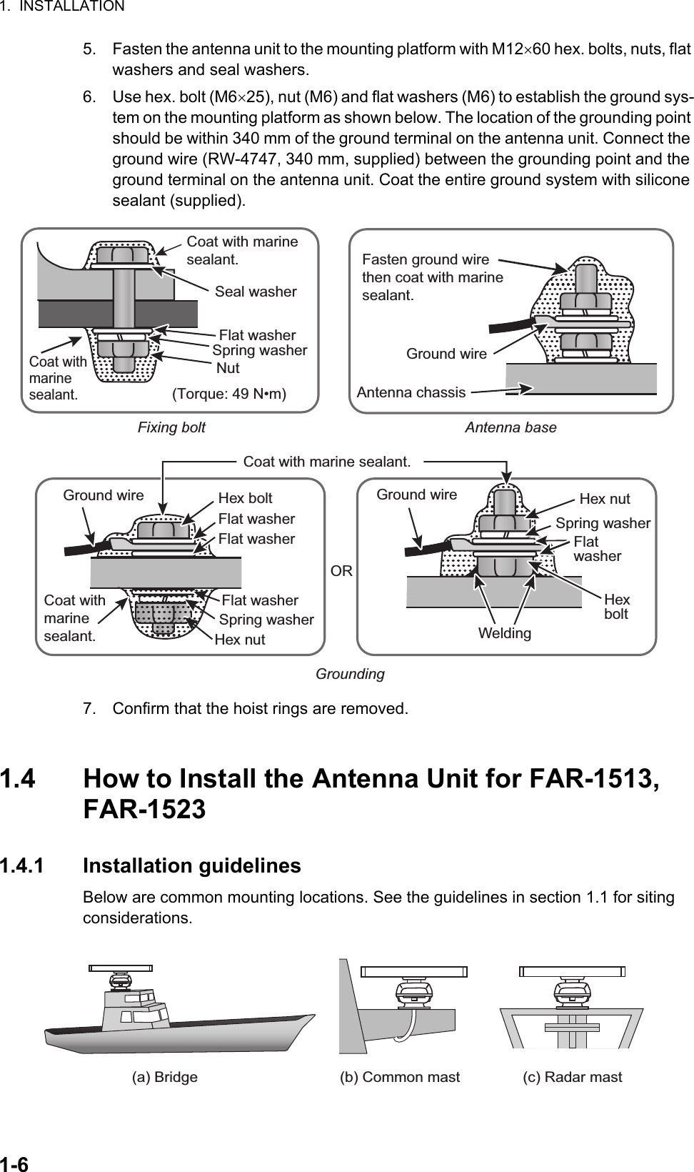
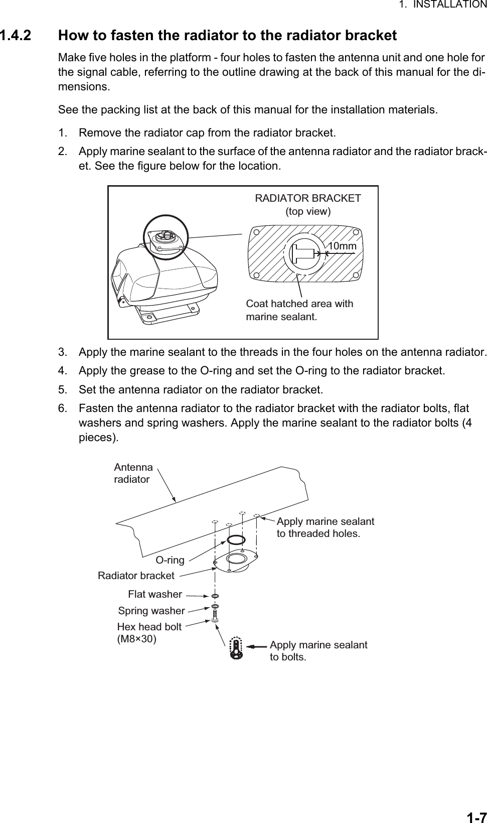
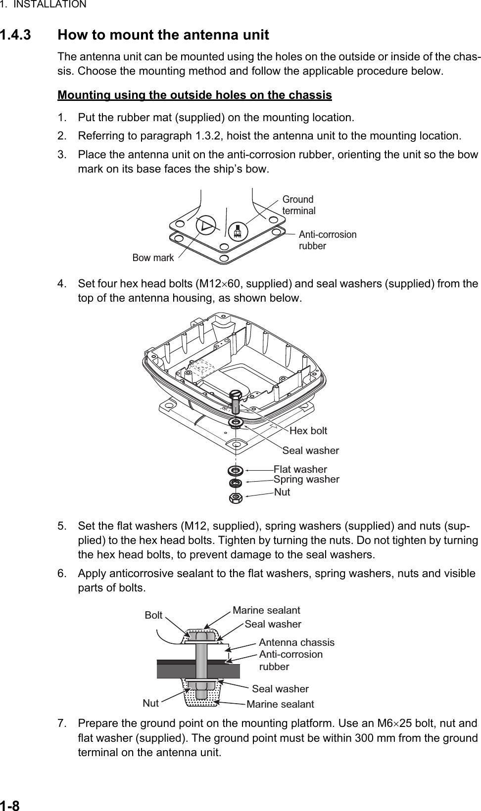
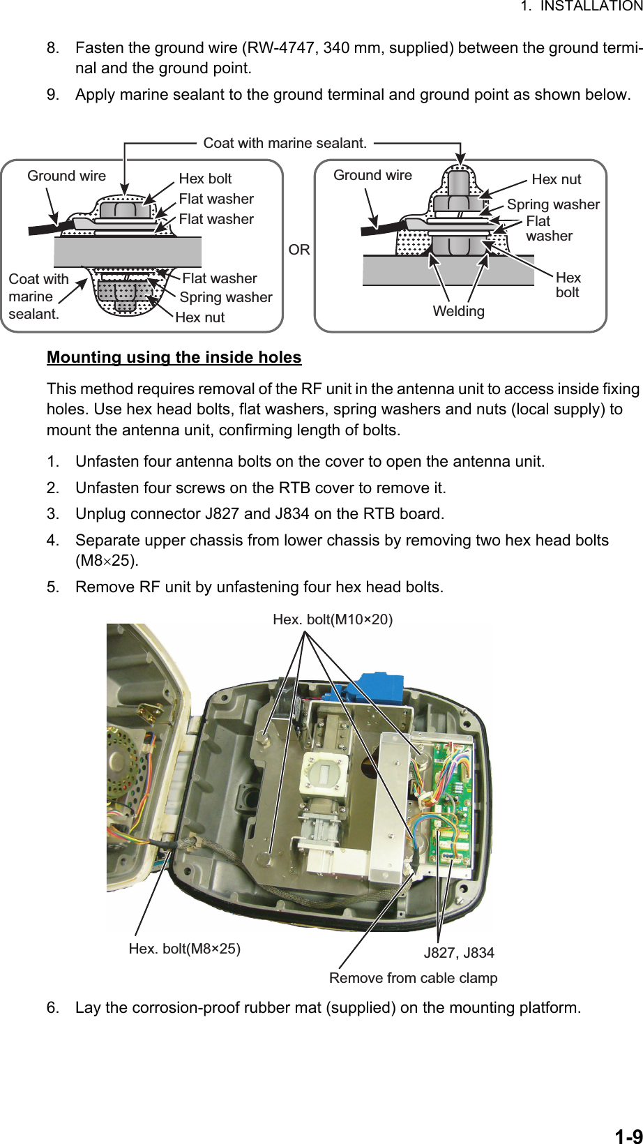
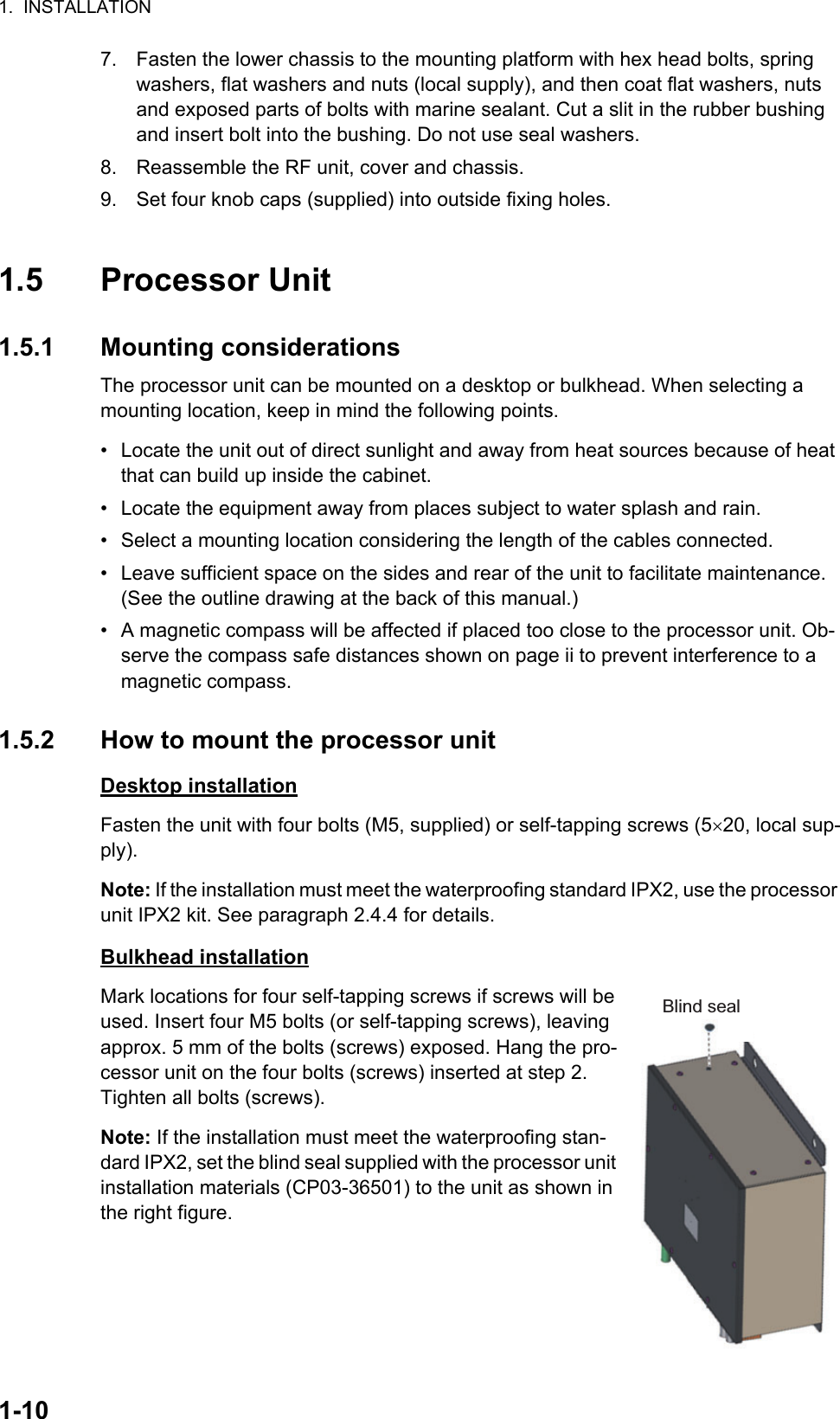
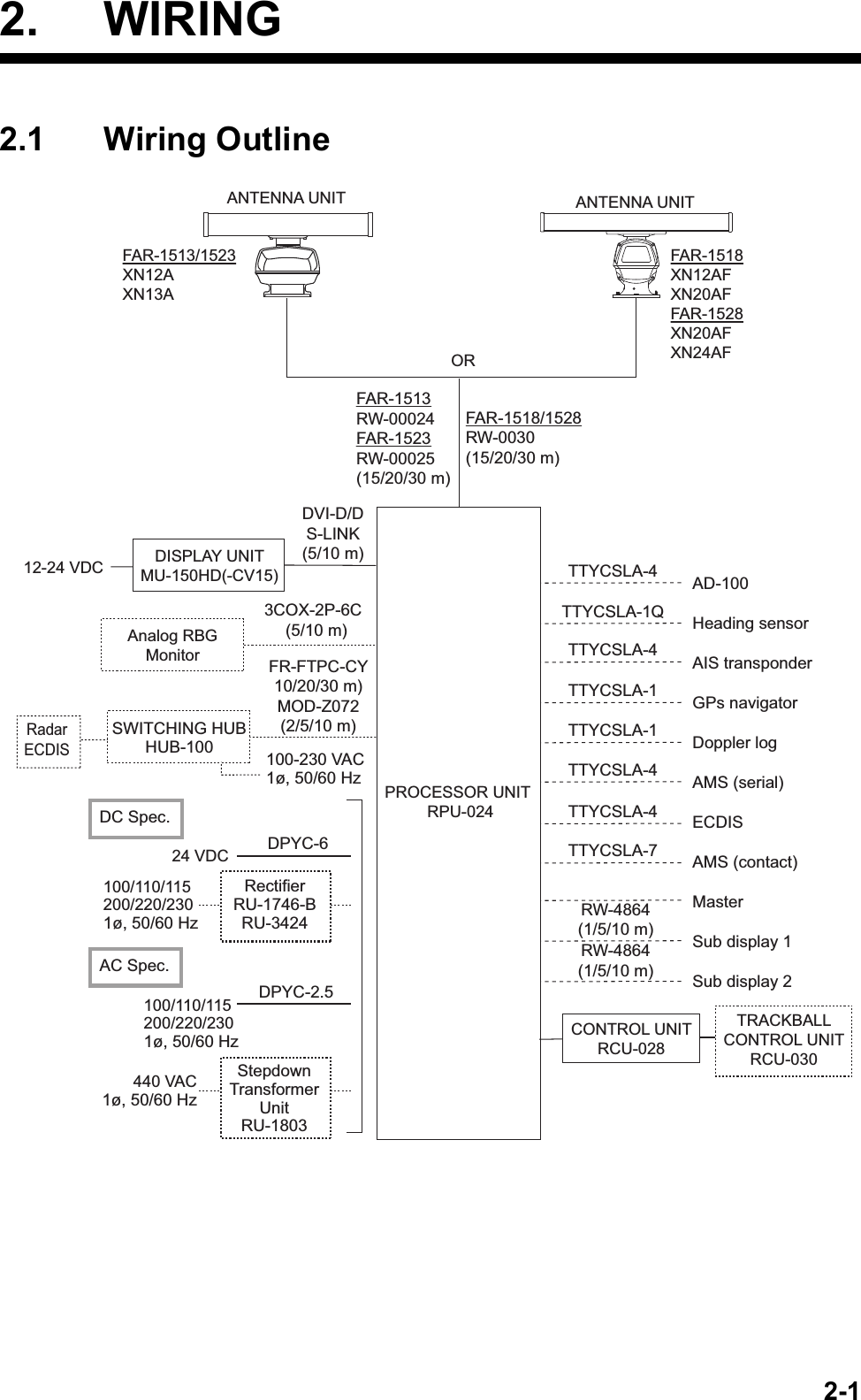
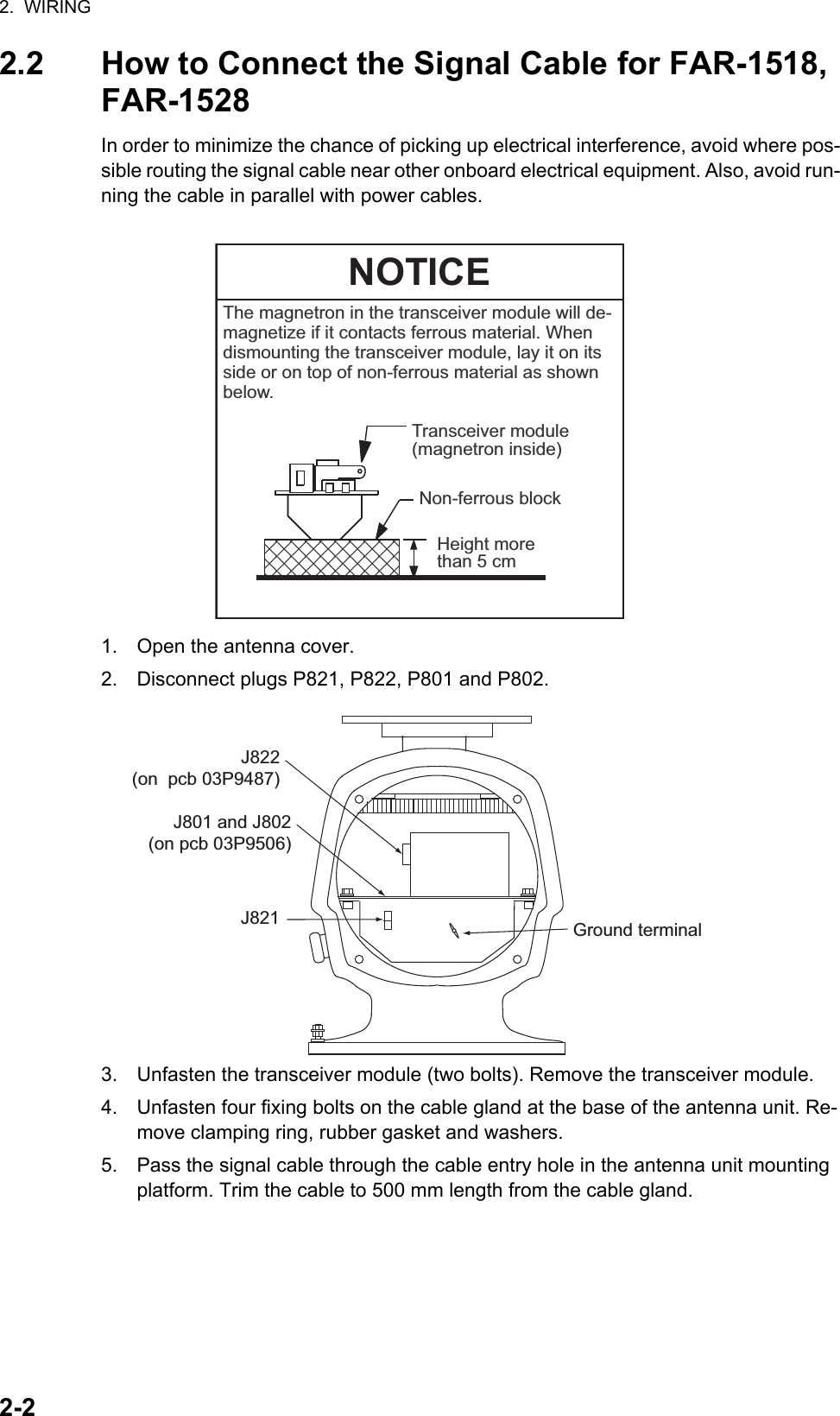
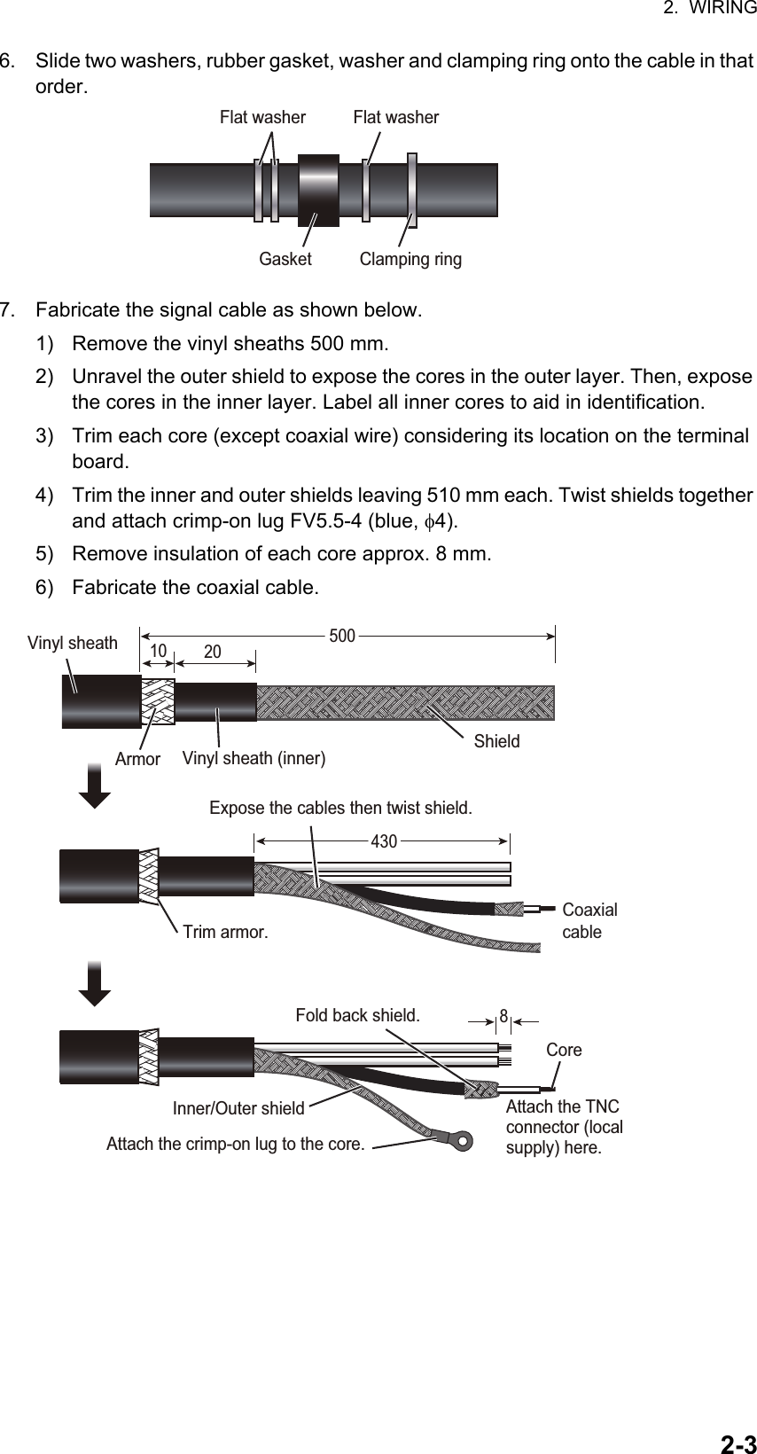
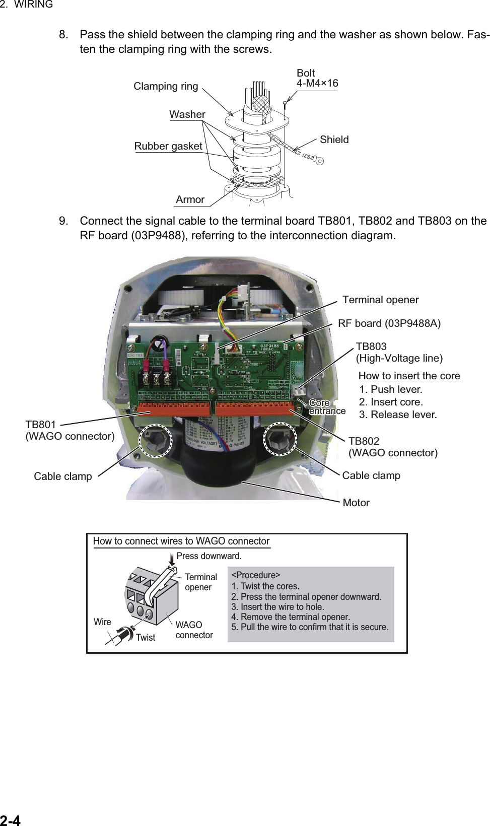
Installation Manual Part 1

www.furuno.comAll brand and product names are trademarks, registered trademarks or service marks of their respective holders.Installation ManualMARINE RADARModel FAR-1513/1513-BB/1523/1523-BB/FAR-1518/1518-BB/1528/1528-BBSAFETY INSTRUCTIONS ................................................................................................ iSYSTEM CONFIGURATION .......................................................................................... iiiEQUIPMENT LIST ........................................................................................................... v1. INSTALLATION.......................................................................................................1-11.1 Before Beginning the Installation... ................................................................................... 1-11.2 Antenna Unit Installation Considerations .......................................................................... 1-21.3 How to Install the Antenna Unit for FAR-1518, FAR-1528................................................ 1-31.4 How to Install the Antenna Unit for FAR-1513, FAR-1523................................................ 1-61.5 Processor Unit ................................................................................................................ 1-101.6 Display Unit..................................................................................................................... 1-111.7 Control Unit ..................................................................................................................... 1-111.8 Trackball Control Unit (option) ........................................................................................ 1-122. WIRING....................................................................................................................2-12.1 Wiring Outline ................................................................................................................... 2-12.2 How to Connect the Signal Cable for FAR-1518, FAR-1528 ............................................ 2-22.3 How to Connect the Signal Cable for FAR-1513, FAR-1523 ............................................ 2-62.4 Processor Unit ................................................................................................................ 2-112.5 Trackball Control Unit ..................................................................................................... 2-192.6 VDR Connection ............................................................................................................. 2-203. ADJUSTMENTS ......................................................................................................3-13.1 How to Open the Radar Installation Menu ........................................................................ 3-13.2 How to Use the Menu ....................................................................................................... 3-23.3 How to Initialize Tuning.....................................................................................................3-23.4 How to Align the Heading ................................................................................................. 3-33.5 How to Adjust Sweep Timing ............................................................................................ 3-43.6 How to Suppress Main Bang ............................................................................................ 3-43.7 RADAR INSTALLATION Menu......................................................................................... 3-54. INPUT/OUTPUT DATA............................................................................................4-14.1 Processor Unit .................................................................................................................. 4-14.2 IEC 61162 Sentences ....................................................................................................... 4-2APPENDIX 1 JIS CABLE GUIDE .............................................................................AP-1APPENDIX 2 DIGITAL INTERFACE ........................................................................AP-2PACKING LISTS ......................................................................................................... A-1OUTLINE DRAWINGS ................................................................................................ D-1INTERCONNECTION DIAGRAM ................................................................................ S-1
The paper used in this manualis elemental chlorine free.・FURUNO Authorized Distributor/Dealer9-52 Ashihara-cho,Nishinomiya, 662-8580, JAPANA:0000Printed in JapanAll rights reserved.Z7:JUL.30, 2015Pub. No.IME-36380-Z7(DAMI)FAR-15X3/15X8/BB
i SAFETY INSTRUCTIONS Mandatory Action Prohibitive ActionWARNINGIndicates a potentially hazardous situation which, if not avoided,could result in death or serious injury. CAUTIONIndicates a potentially hazardous situation which, if not avoided,can result in minor or moderate injury.  Warning, CautionWARNINGRadio Frequency Radiation Hazard  DANGERIndicates a potentially hazardous situation which, if not avoided,will result in death or serious injury. Wear a safety belt and hard hat when working on the antenna unit.Serious injury or death can result if someone falls from the radar antenna mast.DANGERThe radar antenna emits electromagnetic radio  frequency (RF) energy which can be harmful,particularly to your eyes. Never look directly into the antenna aperture from a close distance while the radar is in operation or expose yourself to the transmitting antenna at a close distance. Distances at which RF radiation level of 100 W/m2, 50 W/m2 and 10 W/m2 are given in the table below.If the antenna unit is installed at a close distance in front of the wheel house, your administration may require halt of transmission within a certain sector of antenna revolution. See the installation manual for how to manage blind sectors.The installer of the equipment must read the applicable safety instructions before attempting to install the equipment. Radar model Transceiver Magnetron Antenna100W/m250W/m210W/m2XN12A N/A 2.1 mXN13A N/A 1.9 mXN12A 0.6 m 4.6 mXN13A 0.4 m 3.1 mXN12AF 0.3 m 0.7 m 4.1 mXN20AF 0.2 m 0.5 m 3.1 mXN20AF 0.6 m 1.2 m 6.1 mXN24AF 0.3 m 0.8 m 4.0 mMAF1565NM1458FMAF1615BMG5436FAR-1513FAR-1523FAR-1518FAR-1528RTR-086ARTR-087ARTR-100RTR-101
SAFETY INSTRUCTIONSiiCAUTIONObserve the following compass safe distances to prevent interference to a magnetic compass:Note: For more information, please refer to IMO SN/Circ.271 “Guidelines for the installa-tion of shipborne radar equipment.”  Do not open the equipmentunless totally familiar withelectrical circuits andservice manual.Only qualified personnelare allowed to work inside theequipment.WARNINGELECTRICALSHOCKHAZARDConstruct a suitable service platform from which to install the antenna unit.Serious injury or death can result if someone falls from the radar antenna mast.Turn off the power at the mains switchboard before beginning the installation.Fire, electrical shock or serious injury can result if the power is left on or is applied while the equipment is being installed.Be sure that the power supply is compatible with the voltage rating of the equipment.Connection of an incorrect power supply can cause fire or damage the equipment.Use only the specified power cable.Fire or damage to the equipment can result if a different cable is used.Do not install the processor unit, marine display or a control unit in a dusty environment, or one where the units may get wet from rain or water splash.Dust or water in the units can result in fire, electrical shock, or damage to the equipment.Attach protective earth for processor unit securely to the ship's body.The protective earth (grounding) is required for the AC power supply to prevent electrical shock.Unit StandardcompassSteeringcompassAntenna Unitfor FAR-1513Antenna Unitfor FAR-1523Antenna Unitfor FAR-1518RSB-0070  1.00 m  0.60 mRSB-0073  1.10 m  0.70 mRSB-0070  1.85 m  1.25 mRSB-0073  1.80 m  1.15 mRSB-120 RSB-121  RSB-120  RSB-121 Processor Unit (RPU-024)  2.60 m  1.70 mControl Unit (RCU-028)  0.90 m  0.60 mDisplay Unit (MU-150HD(-CV15))  0.65 m  0.45 mTrackball Control Unit (RCU-030)  0.50 m  0.30 mAntenna Unitfor FAR-15281.55 m  1.00 m2.05 m  1.30 m
iiiSYSTEM CONFIGURATIONFAR-1513(-BB), FAR-1523(-BB)ANTENNA UNITFAR-1513(-BB)XN12A-RSB-0070-086AXN12A-RSB-0073-086AXN13A-RSB-0070-086AXN13A-RSB-0073-086AFAR-1523(-BB)XN12A-RSB-0070-087AXN12A-RSB-0073-087AXN13A-RSB-0070-087AXN13A-RSB-0073-087AEquipment categoryPROCESSOR UNITRPU-024Unit                  CategoryAntenna  Exposed to the weatherOther units  Protected from the weatherCONTROL UNITRCU-028TRACKBALLCONTROL UNITRCU-03012-24 VDC DISPLAY UNITMU-150HD(-CV15)*2SWITCHING HUBHUB-100100-230 VAC1ø, 50/60 HzInterswitchGyrocompass *1, AD-10 formatGyrocompass *1, IEC61162 formatAIS TransponderEPFS (GPS)SDME (Speed log)AMS, IEC61162 formatECDISAMS (Contact)*3Sub Display 1Sub Display 2VDR or Analog RGB Monitor*1: The gyrocompass must also have an update rate that is adequate for the ship’s rate of turn. The update rate must be better than 40 Hz (HSC) or 20 Hz (conventional vessel).*2:This monitor have been approved by the IMO, MU-150HD(-CV15) for CAT 3. If a different monitor is to be used on IMO vessels, its effective diameter must meet the applicable Category requirements (CAT 3: Effective diameter 180 mm or higher). For installation, operation and viewing distance of other monitors, see their respective manuals. For BB types, a monitor is to be prepared by the user.*3: Characteristics of contact output for AMS (Alert Management System):• (Load current) 250 mA• (Polarity) Normally Open: 2 ports, Normally Close: 2 ports100/110/115200/220/2301ø, 50/60 HzDC Spec.24 VDCRectifierRU-1746-BRU-3424
SYSTEM CONFIGURATIONivFAR-1518(-BB), FAR-1528(-BB)Equipment categoryANTENNA UNIT100/110/115200/220/2301ø, 50/60 HzPROCESSOR UNITRPU-02412-24 VDCCONTROL UNITRCU-028TRACKBALLCONTROL UNITRCU-030DISPLAY UNITMU-150HD(-CV15)*2SWITCHING HUBHUB-100100-230 VAC1ø, 50/60 HzInterswitchDC Spec.24 VDCRectifierRU-1746-BRU-3424440 VAC1ø, 50/60 HzAC Spec.StepdownTransformerUnitRU-1803100/110/115200/220/2301ø, 50/60 HzGyrocompass *1, AD-10 formatGyrocompass *1, IEC61162 formatAIS TransponderEPFS (GPS)SDME (Speed log)AMS, IEC61162 formatECDISAMS (Contact)*3Sub Display 1Sub Display 2FAR-1518(-BB)XN12AF-RSB-120-100XN12AF-RSB-121-100XN20AF-RSB-120-100XN20AF-RSB-121-100FAR-1528(-BB)XN20AF-RSB-120-101XN20AF-RSB-121-101XN24AF-RSB-120-101XN24AF-RSB-121-101The radar(s) must be interconnected to the following type approved sensors:  • Gyrocompass meeting requirements of the IMO resolution A.424(XI).  • EPFS meeting the requirements of the IMO resolution MSC.112(73).  • SDME meeting the requirements of the IMO resolution MSC.86(72).The radar may be interconnected via HUB-100 to other FURUNO processing units having approved LAN ports.NOTICE FOR FAR-1518(-BB)/FAR-1528(-BB)VDR or Analog RBG Monitor*1: The gyrocompass must also have an update rate that is adequate for the ship’s rate of turn. The update rate must be better than 40 Hz (HSC) or 20 Hz (conventional vessel).*2:This monitor have been approved by the IMO, MU-150HD(-CV15) for CAT 3. If a different monitor is to be used on IMO vessels, its effective diameter must meet the applicable Category requirements (CAT 3: Effective diameter 180 mm or higher). For installation, operation and viewing distance of other monitors, see their respective manuals. For BB types, a monitor is to be prepared by the user.*3: Characteristics of contact output for AMS (Alert Management System):• (Load current) 250 mA• (Polarity) Normally Open: 2 ports, Normally Close: 2 portsUnit                  CategoryAntenna  Exposed to the weatherOther units  Protected from the weather
vEQUIPMENT LISTStandard supplyName Type Code No. Qty RemarksProcessor Unit RPU-024 - 1Control Unit RCU-028 - 1Display Unit MU-150HD-CV15 - 1Antenna Unit(FAR-1513)XN12A-RSB-0070-086A -Selectone24 rpm, 1200 mmXN12A-RSB-0073-086A - 48 rpm, 1200 mmXN13A-RSB-0070-086A - 24 rpm, 1800 mmXN13A-RSB-0073-086A - 48 rpm, 1800 mmAntenna Unit(FAR-1523)XN12A-RSB-0070-087A -Selectone24 rpm, 1200 mmXN12A-RSB-0073-087A - 48 rpm, 1200 mmXN13A-RSB-0070-087A - 24 rpm, 1800 mmXN13A-RSB-0073-087A - 48 rpm, 1800 mmAntenna UnitFAR-1518)XN12AF-RSB-120-100 -Selectone26 rpm, 1200 mmXN12AF-RSB-121-100 - 48 rpm, 1200 mmXN20AF-RSB-120-100 - 26 rpm, 2000 mmXN20AF-RSB-121-100 - 48 rpm, 2000 mmAntenna Unit(FAR-1528)XN20AF-RSB-120-101 -Selectone26 rpm, 2000 mmXN20AF-RSB-121-101 - 48 rpm, 2000 mmXN24AF-RSB-120-101 - 26 rpm, 2400 mmXN24AF-RSB-121-101 - 48 rpm, 2400 mmInstallationMaterials(FAR-1513)CP03-36700 001-421-520Select one10 m signal cableCP03-36710 001-421-530 15 m signal cableCP03-30720 001-421-540 20 m signal cableCP03-36730 001-421-550 30 m signal cableInstallationMaterials(FAR-1523)CP03-36800 001-423-400Select one10 m signal cableCP03-36810 001-423-410 15 m signal cableCP03-36820 001-423-420 20 m signal cableCP03-36830 001-423-430 30 m signal cableInstallationMaterials(FAR-1518,FAR-1528)CP03-36900 001-423-440Select one15 m signal cableCP03-36910 001-423-450 20 m signal cableCP03-36920 001-423-460 30 m signal cableInstallationMaterialsCP03-36501 001-419-860 1CP03-36601 001-419-600 1Cable Assy. DVI-D/D S-LINK 5M 001-132-960-10 1Spare Parts SP03-18001 001-419-820 1 Fuses (2), for DC power processor unitSpare Parts SP03-18002 001-419-830 1 Fuses (2), for AC power processor unit
EQUIPMENT LISTviOptional supplyName Type Code No. RemarksTrackball Control Unit RCU-030 -Performance Monitor PM-32A 001-419-490Processor Unit IPX2 KitOP03-238 001-419-560Stepdown Transformer UnitRU-1803 - 440 V100 VRectifier RU-3423 - For display unit,current capacity max. 7APR-240 - For display unit,current capacity max. 8ARU-1746B-2 - Current capacity max. 13ARU-3424 - Current capacity max. 20APR-850A - 100/110/120/220/240VAC24 VDC. Currentcapacity max. 30ACable Assy. RW-4864 1M 001-103-620-10 Radar signal cable, 1 mRW-4864 5M 001-103-630-10 Radar signal cable, 5 mRW-4864 10M 001-103-640-10 Radar signal cable, 10 mRW-4864 15M 001-103-650-10 Radar signal cable, 15 mCable Assy. DVI-D/D S-LINK 10M 001-133-980-10 For Display Unit,DVI cable, 10 mSwitching Hub HUB-100 -Installation Materials CP03-28900 000-082-658 10 mInstallation Materials CP03-28910 000-082-659 20 mInstallation Materials CP03-28920 000-082-660 30 mFlush Mount Kit OP26-4 001-080-850Hood Assy. OP26-3 001-080-840Bracket Assy. OP26-2 000-016-268LAN Cable MOD-Z072-020+ 001-167-880-10MOD-Z072-050+ 001-167-890-10MOD-Z072-100+ 001-167-900-10Cable Assy. 3COX-2P-6C 5M 001-077-230-103COX-2P-6C 10M 001-077-220-10
1-11. INSTALLATION1.1 Before Beginning the Installation...Please read the instructions below before beginning the installation.•  Do the installation following the instructions contained in this manual.•  Be sure to do the installation setup (tuning, timing, heading alignment, etc.) in chap-ter 3 after installing the equipment.•  The cable names mentioned throughout this manual are JIS (Japan Industrial Stan-dard) cables. If not available locally, see Appendix 1 for the equivalent cables.•  The control unit cannot be mounted in a console - it is designed to be mounted on a desktop.•  See the table below for retrofit possibility. For use of the existing antenna cable of FR-8125 or FR-8255, attachment of a connector (NH and VH) to the cable is nec-essary. However, replacement of the cable is recommended.•  The antenna cable for the FAR-1513/FAR-1523 has connectors at both its ends. If the cable is to be passed through a bulkhead, do not remove the connectors (to make it easier to pass the cable through the bulkhead). Make an opening in the bulkhead large enough to pass the connectors.•  Use only the specified power cable and fuse.•  Connect the DC power specification processor unit to the ship’s mains via a break-er.•  Ground the AC power specification processor unit.•  If the processor unit is to be installed near where water or rain splash may occur, install the optional waterproofing kit, which provides waterproofing standard IPX2. Do not install the unit in an area where water or rain splash exceeds the conditions of IPX2.•  Do not connect the radar to the ship’s onboard LAN.•  Connect the drain wires of external equipment to the specified locations in the pro-cessor unit to prevent noise.•  Do not disassemble the equipment, to prevent electrical shock.•  Do not apply paint, anti-corrosive sealant or contact spray to coating or plastic parts of the equipment. Those items contain organic solvents that can damage coating and plastic parts, especially plastic connectors.•  In case of trouble consult with a FURUNO dealer.•  This series of radars are supplied with or without (BB type) a monitor. The configu-ration is identical otherwise.Retrofit possibilityFAR-1513/1523FAR-1518/1528(no Performance Monitor)FAR-1518/1528(w/Performance Monitor)FR-8002 series Yes No NoFR-1500 MK3 series Yes Yes No
1.  INSTALLATION1-21.2 Antenna Unit Installation Considerations•  The antenna unit is generally installed either on top of the wheelhouse or on the ra-dar mast, on a suitable platform. Locate the antenna unit in an elevated position to permit maximum target visibility.•  A line of sight from the antenna unit to the bow of the ship must hit the surface of the sea in not more than 500 m or twice the ship’s length, depending whichever val-ue is smaller, for all load and trim conditions.•  Install the antenna unit so that any blind sectors caused by objects (mast, etc.) are kept to a minimum. A blind sector must not exist in arc of the horizon from right ahead to 22.5° aft of the beam to either side (see the figure below). Also, individual blind sectors of more than 5° or the total arc of both blind sectors of more than 20°, must not occur in the remaining arc (Figure 2). Note that any two blind sectors sep-arated by 3° or less are regarded as one sector.•  Do not install the antenna where extreme winds may strike the port and starboard sides of the antenna.•  Install the antenna unit away from interfering high-power energy sources and TX ra-dio antennas.•  Keep the following distance and angle between another radar antenna.•  Keep the lower edge of the antenna unit above the safety rail by at least 500 mm.less than 500 m or twice the ship's lengthFigure 1 Figure 2less than 3°22.5°22.5°270° 90°a, b, c: less than 5° respectivelya+b+c+: less than 20°a, b, c: less than 5° respectivelya+b+c+: less than 20°More than 20°More than 1 m
1.  INSTALLATION1-3•  No funnel, mast or derrick shall be within the vertical beamwidth of the antenna unit in the bow direction, especially zero degree ±5° to prevent blind sectors and false echoes on the radar picture.•  It is rarely possible to place the antenna unit where a completely clear view in all directions is available. Therefore, determine the angular width and relative bearing of any shadow sectors for their influence on the radar at the first opportunity after fitting.•  Locate the antenna of an EPFS clear of the radar antenna to prevent interference to the EPFS. A separation of more than two meters is recommended.•  A magnetic compass will be affected if the antenna unit is placed too close to the compass. Observe the compass safe distances on page ii to prevent interference to a magnetic compass.•  Do not paint the radiator aperture, to ensure proper emission of the radar waves.•  Ground the antenna unit with the supplied ground wire.•  Deposits and fumes from a funnel or other exhaust vent can affect the aerial perfor-mance and hot gases may distort the radiator portion. Do not install the antenna unit where the temperature is more than 55°.•  Leave sufficient space around the unit for maintenance and servicing. See the an-tenna unit outline drawing for recommended maintenance space.Note: For the IMO radar, please refer to IMO SN/Circ.271 "Guidelines for the installa-tion of shipborne radar equipment".1.3 How to Install the Antenna Unit for FAR-1518, FAR-15281.3.1 How to fasten the radiator to the radiator bracketThe antenna unit consists of the antenna radiator and the antenna unit chassis, and they are packed separately. Fasten the antenna radiator to the antenna unit chassis as shown below.1. For the XN20AF, XN24AF, Attach two guide pins to the underside of the antenna radiator.2. Remove the waveguide cap from the radiator bracket. The cap may be discarded.3. Coat the waveguide flange with anticorrosive sealant as shown below.Hole for guide pin5 mm Anticorrosive sealantWaveguide capO-ring10 mmHole forguide pin
1.  INSTALLATION1-44. Coat fixing holes for the antenna radiator with anticorrosive sealant.5. Grease the O-ring and set it to the O-ring groove of the radiator flange.6. Set the antenna radiator to the radiator bracket.7. Coat hex bolts M840 with anticorrosive sealant and use them to loosely fasten the antenna radiator to the antenna unit chassis.8. For the XN20AF, XN24AF, remove two guide pins (inserted at step 1), and then tighten fixing bolts.CAUTIONBe sure to remove the guide pins.Injury may result if the guide pins loosen and fall.Antenna radiatorWaveguideRadiator bracketHex bolt XN12AF: M8×35XN20AF, XN24AF: M8×40O-ringGuide pin(XN20AF, XN24AF)
1.  INSTALLATION1-51.3.2 How to mount the antenna unitThe antenna unit may be assembled before hoisting it to the mounting platform. How-ever, do not lift the antenna unit by the radiator. Always lift the unit by its housing. When using a crane or hoist, use the hoist rings which should be fastened to the bolt fixing covers of the antenna housing.1. Construct a suitable mounting platform referring to the outline drawing at the end of this manual.2. Drill four mounting holes of 15 mm diameter and one cable entry hole of about 50 mm diameter in the mounting platform.3. Lay the rubber mat (supplied) on the mounting platform.4. Place the antenna unit on the rubber mat, orienting the unit so the bow mark on its base faces the ship’s bow.• To hoist antenna unit aboard vessel, attach ropes to lifting fixtures and hoist   unit with crane.• To remove load from radiator when hoisting, the length of the rope between    the radiator base and the hook must be at least 130 cm.• To keep the rope away from the radiator, turn the radiator and chassis   approx. 30 degrees as shown below.• BE SURE TO REMOVE THE HOIST RINGS AFTER HOISTING.  130 cmHookLifting fixtureApprox. 30 deg.Approx. 30 deg.Lifting fixture(Top view)Hoist ringsHoist ringsNO!How to Hoist the Antenna UnitGroundterminalAnti-corrosion rubberBow mark
1.  INSTALLATION1-65. Fasten the antenna unit to the mounting platform with M1260 hex. bolts, nuts, flat washers and seal washers.6. Use hex. bolt (M625), nut (M6) and flat washers (M6) to establish the ground sys-tem on the mounting platform as shown below. The location of the grounding point should be within 340 mm of the ground terminal on the antenna unit. Connect the ground wire (RW-4747, 340 mm, supplied) between the grounding point and the ground terminal on the antenna unit. Coat the entire ground system with silicone sealant (supplied).7. Confirm that the hoist rings are removed.1.4 How to Install the Antenna Unit for FAR-1513, FAR-15231.4.1 Installation guidelinesBelow are common mounting locations. See the guidelines in section 1.1 for siting considerations. Hex boltORGround wireWeldingHex nutGroundingHex boltFlat washerHex nutSpring washerFlat washer Flat washerSpring washerGround wireCoat with marine sealant.Flat washerCoat with marine sealant.Seal washer(Torque: 49 N•m)Flat washerSpring washerFasten ground wire then coat with marine sealant.Ground wireAntenna chassisNutFixing bolt Antenna baseCoat with marine sealant.Coat with marine sealant.(a) Bridge (b) Common mast (c) Radar mast
1.  INSTALLATION1-71.4.2 How to fasten the radiator to the radiator bracketMake five holes in the platform - four holes to fasten the antenna unit and one hole for the signal cable, referring to the outline drawing at the back of this manual for the di-mensions. See the packing list at the back of this manual for the installation materials.1. Remove the radiator cap from the radiator bracket.2. Apply marine sealant to the surface of the antenna radiator and the radiator brack-et. See the figure below for the location.3. Apply the marine sealant to the threads in the four holes on the antenna radiator.4. Apply the grease to the O-ring and set the O-ring to the radiator bracket.5. Set the antenna radiator on the radiator bracket.6. Fasten the antenna radiator to the radiator bracket with the radiator bolts, flat washers and spring washers. Apply the marine sealant to the radiator bolts (4 pieces). RADIATOR BRACKET(top view)Coat hatched area withmarine sealant.10mmFlat washerSpring washerHex head bolt(M8×30)Radiator bracketApply marine sealant to bolts.AntennaradiatorO-ringApply marine sealantto threaded holes.
1.  INSTALLATION1-81.4.3 How to mount the antenna unitThe antenna unit can be mounted using the holes on the outside or inside of the chas-sis. Choose the mounting method and follow the applicable procedure below.Mounting using the outside holes on the chassis1. Put the rubber mat (supplied) on the mounting location.2. Referring to paragraph 1.3.2, hoist the antenna unit to the mounting location.3. Place the antenna unit on the anti-corrosion rubber, orienting the unit so the bow mark on its base faces the ship’s bow.4. Set four hex head bolts (M1260, supplied) and seal washers (supplied) from the top of the antenna housing, as shown below.5. Set the flat washers (M12, supplied), spring washers (supplied) and nuts (sup-plied) to the hex head bolts. Tighten by turning the nuts. Do not tighten by turning the hex head bolts, to prevent damage to the seal washers.6. Apply anticorrosive sealant to the flat washers, spring washers, nuts and visible parts of bolts.7. Prepare the ground point on the mounting platform. Use an M625 bolt, nut and flat washer (supplied). The ground point must be within 300 mm from the ground terminal on the antenna unit.GroundterminalAnti-corrosion rubberBow markHex boltSeal washerFlat washerSpring washerNutSeal washerAntenna chassisAnti-corrosionrubberSeal washerMarine sealantMarine sealantBoltNut
1.  INSTALLATION1-98. Fasten the ground wire (RW-4747, 340 mm, supplied) between the ground termi-nal and the ground point.9. Apply marine sealant to the ground terminal and ground point as shown below.Mounting using the inside holesThis method requires removal of the RF unit in the antenna unit to access inside fixing holes. Use hex head bolts, flat washers, spring washers and nuts (local supply) to mount the antenna unit, confirming length of bolts.1. Unfasten four antenna bolts on the cover to open the antenna unit.2. Unfasten four screws on the RTB cover to remove it.3. Unplug connector J827 and J834 on the RTB board.4. Separate upper chassis from lower chassis by removing two hex head bolts (M825).5. Remove RF unit by unfastening four hex head bolts.6. Lay the corrosion-proof rubber mat (supplied) on the mounting platform.Hex boltORGround wireWeldingHex nutHex boltFlat washerHex nutSpring washerFlat washer Flat washerSpring washerGround wireCoat with marine sealant.Flat washerCoat with marine sealant.Hex. bolt(M10×20)Hex. bolt(M8×25) J827, J834Remove from cable clamp
1.  INSTALLATION1-107. Fasten the lower chassis to the mounting platform with hex head bolts, spring washers, flat washers and nuts (local supply), and then coat flat washers, nuts and exposed parts of bolts with marine sealant. Cut a slit in the rubber bushing and insert bolt into the bushing. Do not use seal washers.8. Reassemble the RF unit, cover and chassis.9. Set four knob caps (supplied) into outside fixing holes.1.5 Processor Unit1.5.1 Mounting considerationsThe processor unit can be mounted on a desktop or bulkhead. When selecting a mounting location, keep in mind the following points.•  Locate the unit out of direct sunlight and away from heat sources because of heat that can build up inside the cabinet.•  Locate the equipment away from places subject to water splash and rain.•  Select a mounting location considering the length of the cables connected.•  Leave sufficient space on the sides and rear of the unit to facilitate maintenance. (See the outline drawing at the back of this manual.)•  A magnetic compass will be affected if placed too close to the processor unit. Ob-serve the compass safe distances shown on page ii to prevent interference to a magnetic compass.1.5.2 How to mount the processor unitDesktop installationFasten the unit with four bolts (M5, supplied) or self-tapping screws (520, local sup-ply).Note: If the installation must meet the waterproofing standard IPX2, use the processor unit IPX2 kit. See paragraph 2.4.4 for details.Bulkhead installationMark locations for four self-tapping screws if screws will be used. Insert four M5 bolts (or self-tapping screws), leaving approx. 5 mm of the bolts (screws) exposed. Hang the pro-cessor unit on the four bolts (screws) inserted at step 2. Tighten all bolts (screws).Note: If the installation must meet the waterproofing stan-dard IPX2, set the blind seal supplied with the processor unit installation materials (CP03-36501) to the unit as shown in the right figure.Blind seal
1.  INSTALLATION1-111.6 Display UnitSee the operator's manual for MU-150HD (OMC-44560) for the installation procedure. Keep in mind the following points when selecting a location.•  Locate the display unit where no framing is installed immediately forward of the dis-play unit.•  Locate the display unit where it is easy to view the display in all ambient lighting con-ditions.1.7 Control UnitThe control unit is designed to be fixed to a desktop. Install the control unit within five meters from the processor unit since the length of the cable connecting them is five meters.1. Drill four mounting holes of 5 mm diameter referring to the outline drawing at the back of this manual.2. Fix the control unit with four self-tapping screws (4, local supply) from the top of the control unit. Make the screws are long enough.3. Attach four cosmetic caps to the fixing holes on the control unit.Note: A plastic bag is attached to the end of the USB cable at the factory to fulfill the requirements for waterproofing standard IPX2. If the waterproofing standard is re-quired, do not remove the plastic bag.Bridge windowViewing pointViewing pointViewing pointViewing pointBridge windowFixing hole
1.  INSTALLATION1-121.8 Trackball Control Unit (option)How to mount the unit tiltedUse the desk fixing plate to mount the unit tilted. Fasten the desk fixing plate to the bottom of the control unit. Fasten the control unit with self-tapping screws (local sup-ply).How to mount the unit flush with mounting surfaceDrill four mounting holes of 5 mm in diameter referring to the outline drawing at the back of this manual. Fasten the control unit with four M4 screws (local supply) from the underside of the desktop.Desk fixing plate
2-12. WIRING2.1 Wiring OutlineANTENNA UNIT100/110/115200/220/2301ø, 50/60 HzPROCESSOR UNITRPU-02412-24 VDC DISPLAY UNITMU-150HD(-CV15)Analog RBGMonitorSWITCHING HUBHUB-100 100-230 VAC1ø, 50/60 HzDC Spec.24 VDCRectifierRU-1746-BRU-3424440 VAC1ø, 50/60 HzAC Spec.StepdownTransformerUnitRU-1803100/110/115200/220/2301ø, 50/60 HzFAR-1518XN12AFXN20AFFAR-1528XN20AFXN24AFDVI-D/D S-LINK(5/10 m)3COX-2P-6C(5/10 m)FR-FTPC-CY10/20/30 m)MOD-Z072(2/5/10 m)RadarECDISFAR-1518/1528RW-0030(15/20/30 m) CONTROL UNITRCU-028TRACKBALLCONTROL UNITRCU-030AD-100Heading sensorAIS transponderGPs navigatorDoppler logAMS (serial)ECDISAMS (contact)MasterSub display 1Sub display 2TTYCSLA-4TTYCSLA-1QTTYCSLA-4TTYCSLA-1TTYCSLA-1TTYCSLA-4TTYCSLA-4TTYCSLA-7RW-4864(1/5/10 m)RW-4864(1/5/10 m)DPYC-6DPYC-2.5FAR-1513/1523XN12AXN13AANTENNA UNITORFAR-1513RW-00024FAR-1523RW-00025(15/20/30 m)
2.  WIRING2-22.2 How to Connect the Signal Cable for FAR-1518, FAR-1528In order to minimize the chance of picking up electrical interference, avoid where pos-sible routing the signal cable near other onboard electrical equipment. Also, avoid run-ning the cable in parallel with power cables. 1. Open the antenna cover.2. Disconnect plugs P821, P822, P801 and P802.3. Unfasten the transceiver module (two bolts). Remove the transceiver module.4. Unfasten four fixing bolts on the cable gland at the base of the antenna unit. Re-move clamping ring, rubber gasket and washers.5. Pass the signal cable through the cable entry hole in the antenna unit mounting platform. Trim the cable to 500 mm length from the cable gland.Transceiver module(magnetron inside)Height morethan 5 cmNon-ferrous block The magnetron in the transceiver module will de-magnetize if it contacts ferrous material. Whendismounting the transceiver module, lay it on itsside or on top of non-ferrous material as shownbelow.NOTICEJ801 and J802(on pcb 03P9506)J822(on  pcb 03P9487)Ground terminalJ821
2.  WIRING2-36. Slide two washers, rubber gasket, washer and clamping ring onto the cable in that order.7. Fabricate the signal cable as shown below.1)  Remove the vinyl sheaths 500 mm.2)  Unravel the outer shield to expose the cores in the outer layer. Then, expose the cores in the inner layer. Label all inner cores to aid in identification.3)  Trim each core (except coaxial wire) considering its location on the terminal board.4)  Trim the inner and outer shields leaving 510 mm each. Twist shields together and attach crimp-on lug FV5.5-4 (blue, 4).5)  Remove insulation of each core approx. 8 mm.6)  Fabricate the coaxial cable.Flat washerGasket Clamping ringFlat washer5005002020Vinyl sheathArmor ShieldAttach the crimp-on lug to the core.Inner/Outer shieldFold back shield.Attach the TNC connector (local supply) here.CoreCoaxial cable10108Vinyl sheath (inner)Trim armor.Expose the cables then twist shield.Expose the cables then twist shield.430430
2.  WIRING2-48. Pass the shield between the clamping ring and the washer as shown below. Fas-ten the clamping ring with the screws.9. Connect the signal cable to the terminal board TB801, TB802 and TB803 on the RF board (03P9488), referring to the interconnection diagram.Clamping ringWasherRubber gasketBolt 4-M4×16ShieldArmorTerminal openerRF board (03P9488A)TB803 (High-Voltage line)TB802 (WAGO connector)Cable clampMotorTB801(WAGO connector)Cable clampCoreentranceCoreentranceHow to insert the core1. Push lever.2. Insert core.3. Release lever.Wire How to connect wires to WAGO connectorPress downward.TerminalopenerWAGOconnector Twist<Procedure>1. Twist the cores.2. Press the terminal opener downward.3. Insert the wire to hole.4. Remove the terminal opener.5. Pull the wire to confirm that it is secure.

Navigation menu