Furuno USA 9ZWRTR100 Transceiver for Radar model FAR-1518/1528 User Manual OME 36380 A
Furuno USA Inc Transceiver for Radar model FAR-1518/1528 OME 36380 A
Contents
- 1. Installation Manual Part 3
- 2. Installation Manual Part 1
- 3. Installation Manual Part 2
- 4. Installation Manual Part 4
- 5. Installation Manual Part 5
- 6. Installation Manual Part 6
- 7. User Manual Part 1
- 8. User Manual Part 2
- 9. User Manual Part 3
- 10. User Manual Part 4
- 11. User Manual Part 5
- 12. User Manual Part 6
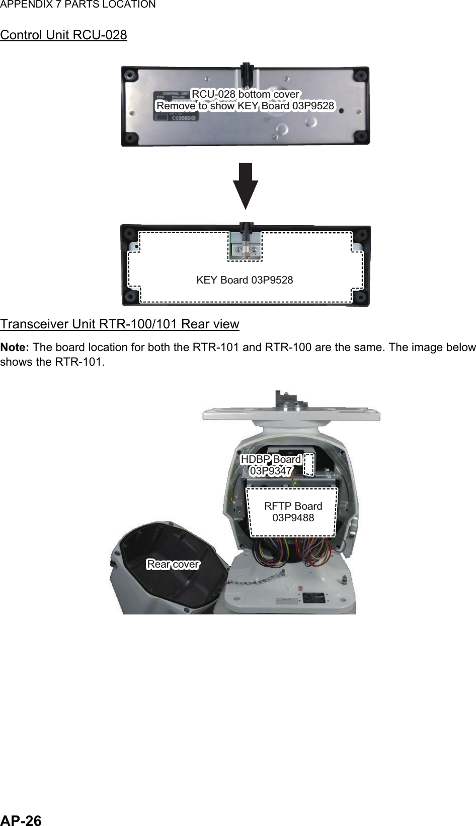
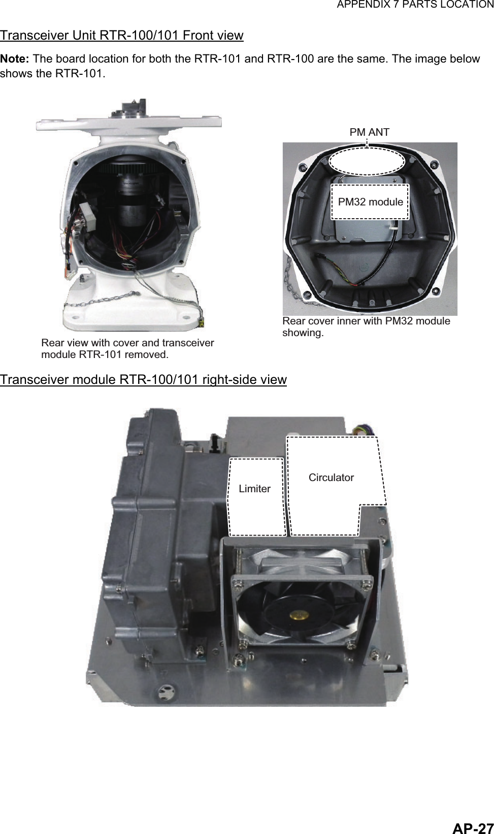
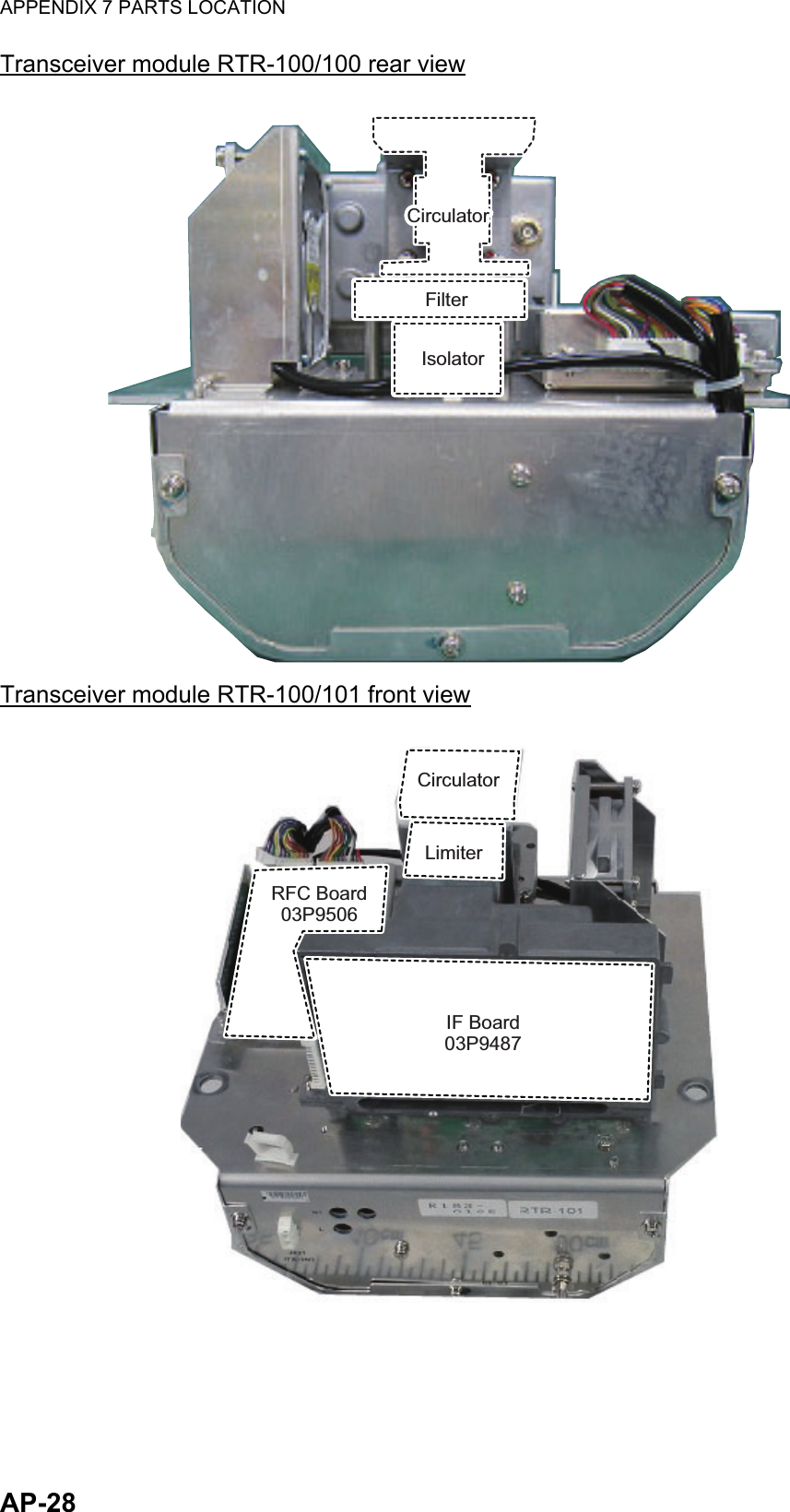
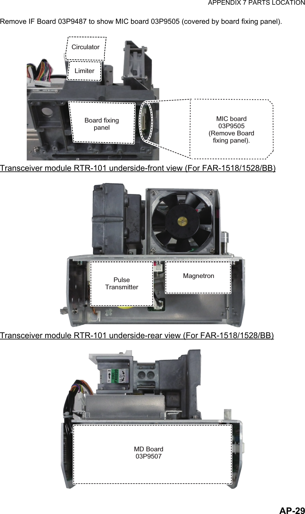
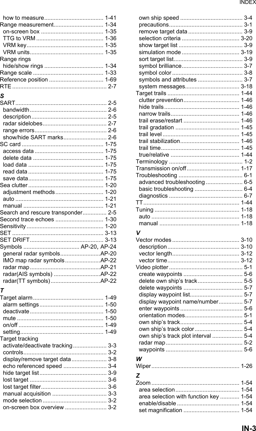
User Manual Part 6
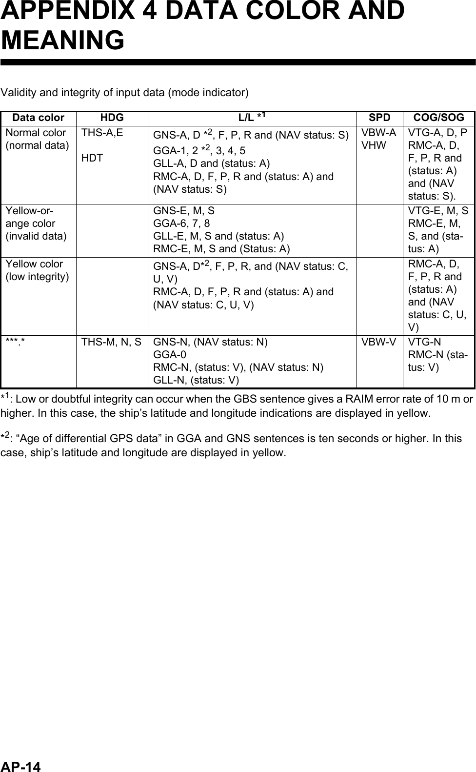
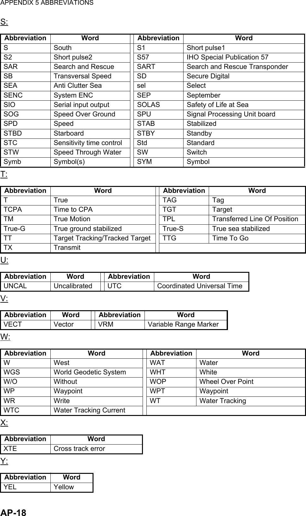
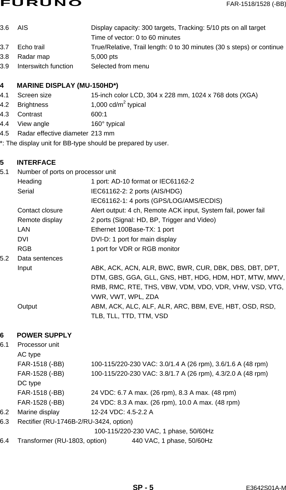
![APPENDIX 3 ALERT CODES, MESSAGES AND MEANINGSAP-11ALR format alertsAlert code Alert title Priority & Category Explanation522 TT TARGET 95%(AUTO) CautionCat: AAutomatically acquired target capacity has reached 95%.Remedy: Press the ALERT ACK key. Remove TT symbols manually.523 TT TARGET FULL(AUTO) WarningCat: AAutomatically acquired target capacity has reached 100%.Remedy: Press the ALERT ACK key. Remove TT symbols manually.524 TT TARGET 95% (MAN) CautionCat: AManually acquired target capacity has reached 95%.Remedy: Press the ALERT ACK key. Remove TT symbols manually.525 TT TARGET FULL(MAN) WarningCat: AManually acquired target capacity has reached 100%.Remedy: Press the ALERT ACK key. Remove TT symbols manually.530 AIS DISPLAY 95% CautionCat: AAIS display capacity has reached 95% (285 targets).Remedy: Press the ALERT ACK key. Adjust [AIS DISP FILTER] settings to decrease the number of targets displayed.531 AIS DISPLAY FULL WarningCat: AAIS display capacity has reached 100% (300 targets).Remedy: Press the ALERT ACK key. Adjust [AIS DISP FILTER] settings to decrease the number of targets displayed.533 AIS CAPACITY FULL CautionCat: AAIS capacity has reached 100% (1000 targets).Remedy: Press the ALERT ACK key. Adjust [AIS DISP FILTER] settings to decrease the number of targets displayed.534 AIS ACTIVATE 95% CautionCat: AActive AIS target capacity has reached 95% (38 targets).Remedy: Press the ALERT ACK key. Adjust [AIS DISP FILTER] settings to decrease the number of targets displayed.535 AIS ACTIVATE FULL WarningCat: AActive AIS target capacity has reached 100% (40 targets).Remedy: Press the ALERT ACK key. Adjust [AIS DISP FILTER] settings to decrease the number of targets displayed.526 TT COLLISION AlarmCat: ATT is within CPA/TCPA threshold, danger of collision. Remedy: Press the ALERT ACK key. Take evasive action if necessary. Adjust CPA/TCPA settings.536 AIS COLLISION AlarmCat: AAIS target is within CPA/TCPA threshold, danger of collision.Remedy: Press the ALERT ACK key. Take evasive action if necessary. Adjust CPA/TCPA settings.521 TT NEW TARGET WarningCat: AA new TT target has entered the Acquisition Zone.Remedy: Press the ALERT ACK key. Confirm location of new target.529 AIS NEW TARGET WarningCat: AA new AIS target has entered the Acquisition Zone.Remedy: Press the ALERT ACK key. Confirm location of new target.527 TT LOST WarningCat: ATT target is lost.Remedy: Press the ALERT ACK key. Lost target indication (blinking in red) is removed.528 REF TARGET LOST WarningCat: AREF targets is lost.](https://usermanual.wiki/Furuno-USA/9ZWRTR100.User-Manual-Part-6/User-Guide-2768730-Page-2.png)
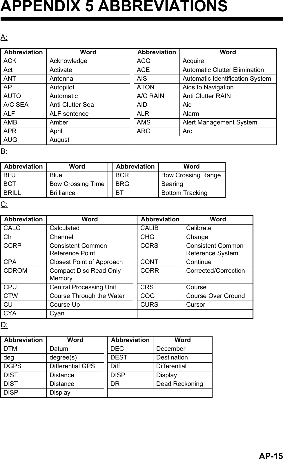
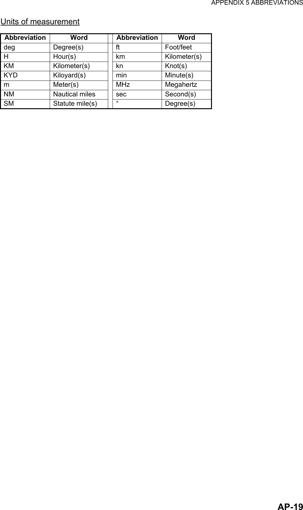
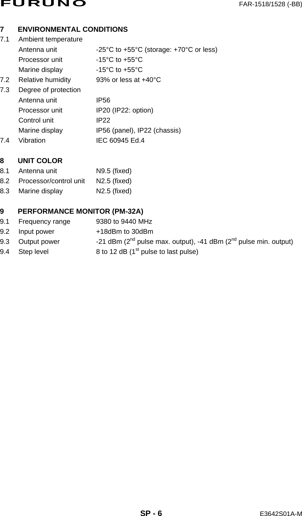
![APPENDIX 3 ALERT CODES, MESSAGES AND MEANINGSAP-12Remedy: Press the ALERT ACK key. Lost target indication (blinking in red) is removed.537 AIS LOST WarningCat: AAIS target is lost.Remedy: Press the ALERT ACK key. Lost target indication (blinking in red) is removed.720 HEADLINE WarningCat: BHeading signal interrupted/lost.Remedy: Press the ALERT ACK key. Restore signal or rectify reason for signal loss.721 AZIMUTH WarningCat: BAzimuth signal is interrupted/lost.Remedy: Press the ALERT ACK key. Restore signal or rectify reason for signal loss.722 TRIGGER WarningCat: BOutput trigger interrupted/lostRemedy: Press the ALERT ACK key. Restore signal or rectify reason for signal loss.723 VIDEO WarningCat: BVideo signal interrupted/lost.Remedy: Press the ALERT ACK key. Restore signal or rectify reason for signal loss.70 KEY WarningCat: BControl unit signal interrupted/lost.Remedy: Press the ALERT ACK key. Restore signal or rectify reason for signal loss.772 PM COMM ERROR WarningCat: BPM communication error.Remedy: Press the ALERT ACK key. Restore signal or rectify reason for signal loss.48 TUNE ERROR WarningCat: BTUNE error due to faulty settings or malfunction.Remedy: Press the ALERT ACK key. Check tuning settings and adjust as necessary.450 GYRO WarningCat: BNo heading information received from gyrocompass for five seconds.Remedy: Press the ALERT ACK key. Match the on-screen indication with the actual gyrocompass. The indication “HEADING SET” appears. Press the ALERT ACK key to erase the indication.278 LOG(WT) Warning/CautionCat: BNo speed data received for five seconds when [LOG(WT)] is set as speed reference.Remedy: Press the ALERT ACK key. Check SDME sensor. Use a different sensor if necessary.284 LOG(BT) Warning/CautionCat: BNo speed data received for thirty seconds when [LOG(BT)] is set as speed reference.Remedy: Press the ALERT ACK key. Check SDME sensor. Use a different sensor if necessary.170 EPFS WarningCat: BEPFS Error. No speed or position data received from EPFS device for thirty seconds.Remedy: Press the ALERT ACK key. Restore the signal. This indication cannot be erased if the po-sition signal is missing. The indication is automatically removed when the signal is restored.469 DATUM WarningCat: BDTM sentence no received for thirty seconds or erroneous data received.Remedy: Press the ALERT ACK key. Use the WGS-84 datum.272 UTC WarningCat: BUTC error. No date or time data received for thirty seconds.Remedy: Press the ALERT ACK key. Restore the signal to remove this indication.380 AIS RECEIVE WarningCat: BNo AIS data received for thirty seconds.Remedy: Press the ALERT ACK key. Check power and connection to AIS unit.Alert code Alert title Priority & Category Explanation](https://usermanual.wiki/Furuno-USA/9ZWRTR100.User-Manual-Part-6/User-Guide-2768730-Page-3.png)
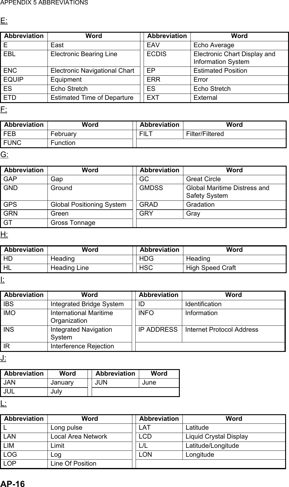
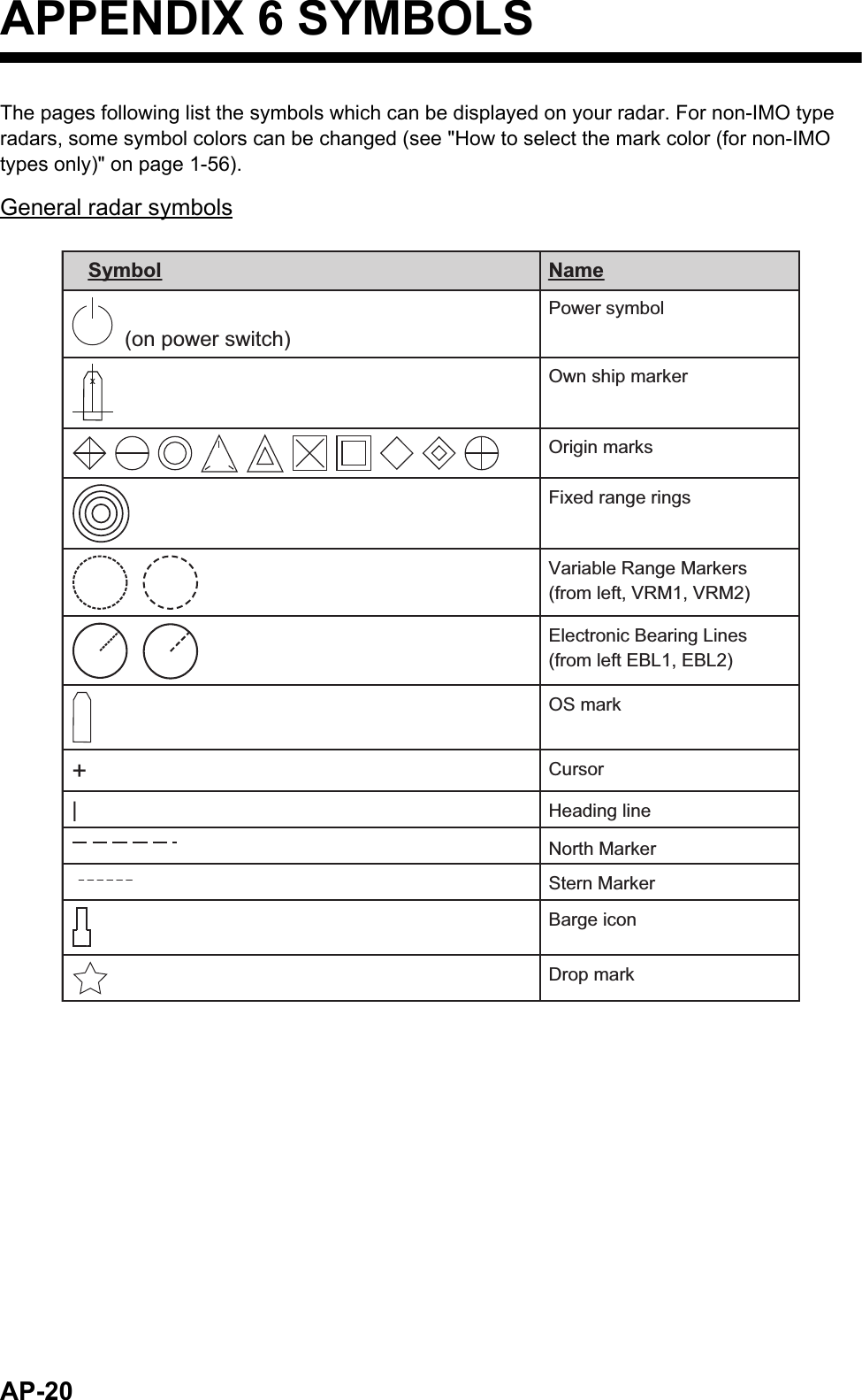
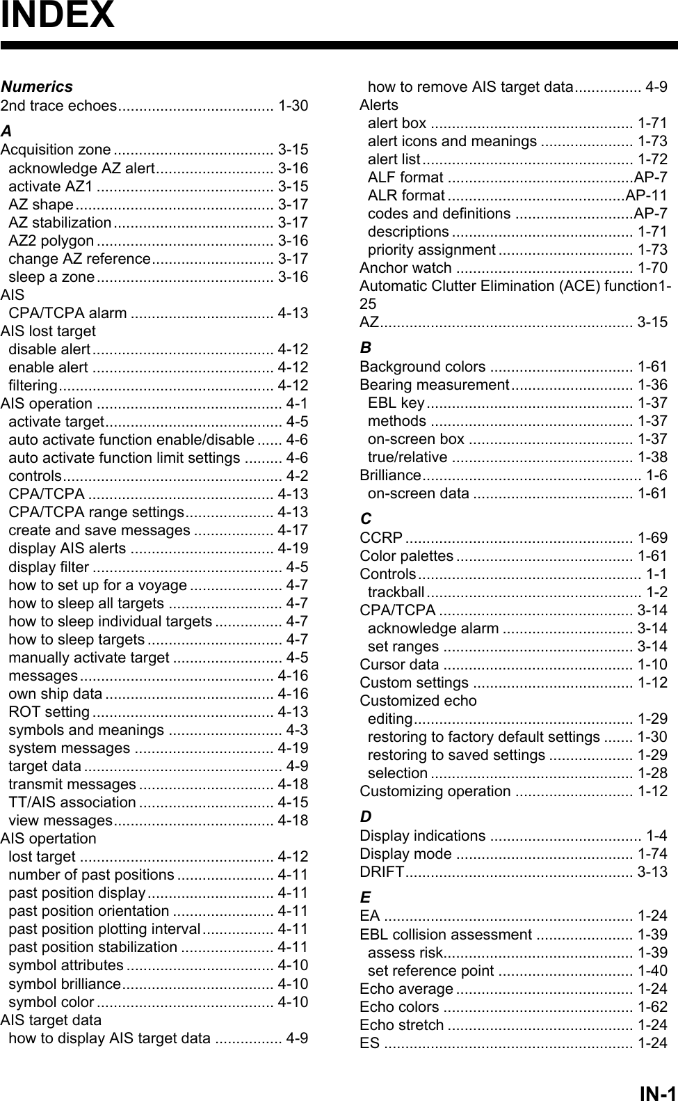
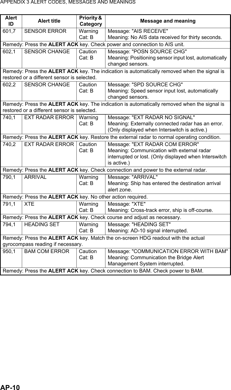
![APPENDIX 3 ALERT CODES, MESSAGES AND MEANINGSAP-13472 POSN SOURCE CHANGE CautionCat: BMessage: "POSN SOURCE CHG"Meaning: Positioning sensor input lost, automati-cally changed sensors.Remedy: Press the ALERT ACK key. The indication is automatically removed when the signal is re-stored or a different sensor is selected.476 SPD SOURCE CHANGE CautionCat: BMessage: "SPD SOURCE CHG"Meaning: Speed sensor input lost, automatically changed sensors.Remedy: Press the ALERT ACK key. The indication is automatically removed when the signal is re-stored or a different sensor is selected.485 DEPTH WarningCat: BDepth is below set threshold.Remedy: Press the ALERT ACK key. Confirm depth. Adjust [DEPTH] settings as required.495 ANCHOR WATCH WarningCat: BShip position outside set anchor watch zone.Remedy: Press the ALERT ACK key. Confirm Own Ship location and adjust as necessary.541 TRANSMIT ERROR CautionCat: BUnable to transmit AIS binary message.Remedy: Press the ALERT ACK key. Check power to AIS unit.542 AIS TRANSMITTING CautionCat: BTransmitting AIS message.Remedy: Press the ALERT ACK key. No other action required.560 ASSOCIATION CautionCat: BOne or more sets of associated targets is displayed.Remedy: Press the ALERT ACK key. Set [ASSOCIATION] to [OFF].740 EXT RADAR NO SIGNAL WarningCat: BExternally connected radar has an error. (Only dis-played when Interswitch is active.)Remedy: Press the ALERT ACK key. Restore the external radar to normal operating condition.750 EXT RADAR COM ERRORCautionCat: BCommunication with external radar interrupted or lost. (Only displayed when Interswitch is active.)Remedy: Press the ALERT ACK key. Check connection and power to the external radar.790 ARRIVAL WarningCat: BShip has entered the destination arrival alert zone.Remedy: Press the ALERT ACK key. No other action required.791 XTE WarningCat: BCross-track error, ship is off-course.Remedy: Press the ALERT ACK key. Check course and adjust as necessary.794 HEADING SET WarningCat: BAD-10 signal interrupted.Remedy: Press the ALERT ACK key. Match the on-screen HDG readout with the actual gyrocompass reading if necessary.950 BAM COM ERROR CautionCat: BCommunication the Bridge Alert Management System interrupted.Remedy: Press the ALERT ACK key. Check connection to BAM. Check power to BAM.Alert code Alert title Priority & Category Explanation](https://usermanual.wiki/Furuno-USA/9ZWRTR100.User-Manual-Part-6/User-Guide-2768730-Page-4.png)