Furuno USA 9ZWRTR100 Transceiver for Radar model FAR-1518/1528 User Manual OME 36380 A
Furuno USA Inc Transceiver for Radar model FAR-1518/1528 OME 36380 A
Contents
- 1. Installation Manual Part 3
- 2. Installation Manual Part 1
- 3. Installation Manual Part 2
- 4. Installation Manual Part 4
- 5. Installation Manual Part 5
- 6. Installation Manual Part 6
- 7. User Manual Part 1
- 8. User Manual Part 2
- 9. User Manual Part 3
- 10. User Manual Part 4
- 11. User Manual Part 5
- 12. User Manual Part 6
User Manual Part 4
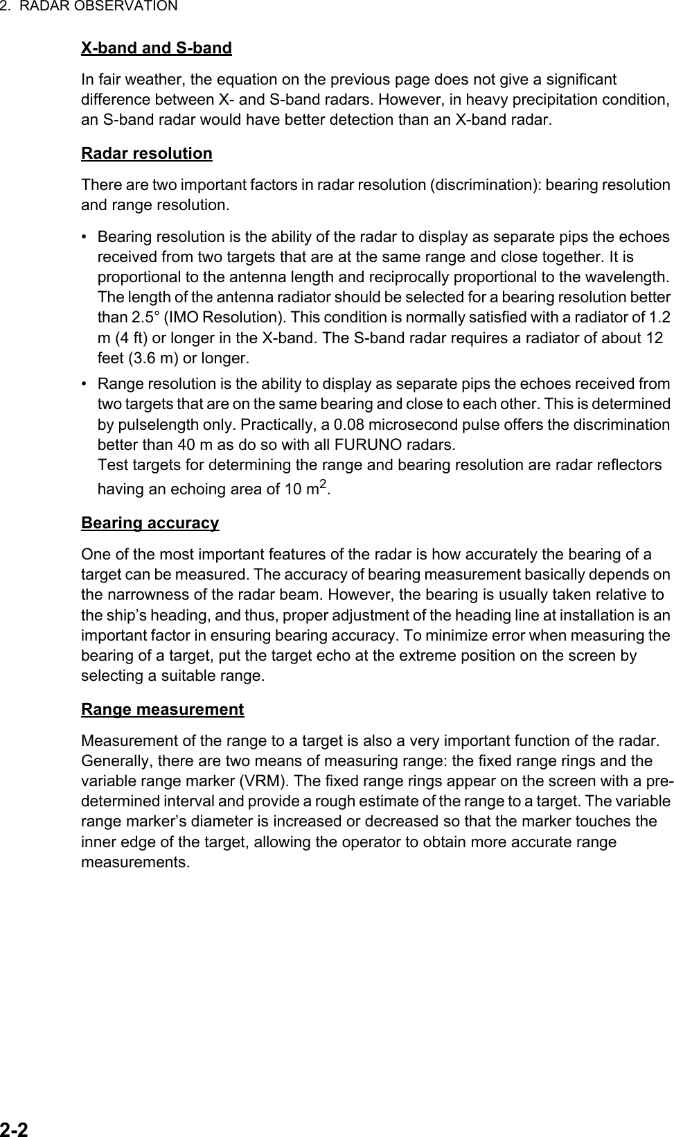
![1. OPERATIONAL OVERVIEW1-681.46.2 How to check the radar’s performanceThe range scale is automatically set to 24 NM. The radar screen will show arcs. If the radar transmitter and receiver are in good working conditions in as much as the original state when the monitor was turned on, the innermost arcs should appear between 8.0 NM to 19.8 NM. The performance monitor can observe a total of 10 dB loss in transmitter and receiver.How to set the number of arcs1. Open the [MAIN MENU].2. Select [ECHO], then press the ADJUST knob.3. Select [PM ARC], then press the ADJUST knob.4. Select [2], [3], [5] or [6] as appropriate, then press the ADJUST knob.5. Close the menu.The figure belows shows an example where [PM ARC] is set to [5].Note 1: The lengths of the arcs can vary according to installation environment. Judge the strength of the echo that appears within 60° from the arc location to confirm if the radar is working properly or not.Note 2: The location of the arcs changes according to the [PM ARC] setting.Turn the performance monitor off when finished.8.0 NM to 19.8 NM8.0 NM to 19.8 NMDisplayRadar StateDisplayTransmitter: normalReceiver: normalTransmitter and receiver: No arc indicates 10 dB loss. Contact your dealer for advice. (For magnetron radars, have a technician check the magnetron.Radar State](https://usermanual.wiki/Furuno-USA/9ZWRTR100.User-Manual-Part-4/User-Guide-2768726-Page-1.png)
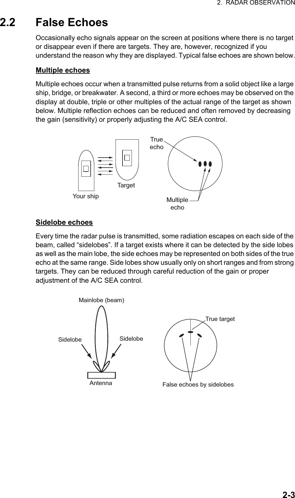
![1. OPERATIONAL OVERVIEW1-691.47 How to Adjust the Reference PositionThe reference position for measurements (range, bearing, etc.) and markers (heading line, stern mark, etc.) can be antenna position or consistent common reference point (CCRP), which is a location on own ship to which all horizontal measurements, for example range, bearing, relative course, relative speed, closest point of approach (CPA) or time to closest point of approach (TCPA), are normally referenced.To adjust the reference position, use the touchpad to place the cursor over the "REF POINT" indication at the top of the screen, then press the left button to select [ANT] or [CCRP] as applicable. You can also adjust the reference by rotating the ADJUST knob when the cursor is placed over the indication.The position of the own ship marker changes according to reference position as shown below. If the CCRP is positioned outside of the effective display area, the bear-ing scale is indicated with the appropriate reduced detail.Range and bearing are measured and graphics are drawn according to reference position as in the table below.Category Item Reference pointANT CCRPRange and bearing measurementsEBL Range and bearing measured from antenna position.Range and bearing measured from CCRP.VRMCursorPI lineRange ringDrop markGraphics Heading line Drawn from antenna position.Drawn from CCRP.Stern markBeam lineOwn ship vectorOwn ship trackBearing cursor Drawn with antenna position at center.Drawn with CCRP at center.Course, speed Calculated with antenna position at center.Calculated with CCRP at center.CPA, TCPA Calculated with antenna position at center.Calculated with CCRP at center.BCR, BCT Calculated from bow position.Continued on next pageXCCRP positionXANT positionRadar antennaposition is atcenter of displayConning position is atcenter of display](https://usermanual.wiki/Furuno-USA/9ZWRTR100.User-Manual-Part-4/User-Guide-2768726-Page-2.png)
![1. OPERATIONAL OVERVIEW1-70Note: When the antenna is located some distance from the CCRP, the CCRP can be outside the bearing cursor in true motion or off-center.Also, when the CCRP is set as reference point, some parts of the bearing cursor are not displayed.1.48 Anchor WatchThe anchor watch feature alerts you when your ship has traveled a distance greater than a threshold value, when it should be at rest. When the anchor watch is active, an orange dashed circle marks the anchor watch range.If your ship goes outside the circle, the indication "ANCHOR WATCH" appears in the [ALERT] box.1. Open the [MAIN MENU].2. Select [ALERT], then press the ADJUST knob.3. Select [ANCHOR WATCH], then press the ADJUST knob.4. Select [ON] to enable [ANCHOR WATCH].5. Using the ADJUST knob, select the distance for the alert. Press the ADJUST knob to apply the setting.6. Close the menu.Own ship data Heading Data is taken from respective sensors, regardless of reference point selected.SpeedCourse over groundSpeed over groundOwn L/L Location of the CCRP.Category Item Reference pointANT CCRPAnchor watch alarm setting Own ship location when anchor watch is setOwn ship moves outside watch zoneAlarm is triggered](https://usermanual.wiki/Furuno-USA/9ZWRTR100.User-Manual-Part-4/User-Guide-2768726-Page-3.png)
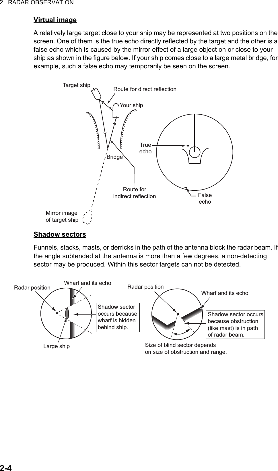
![1. OPERATIONAL OVERVIEW1-711.49 How to Interpret the ALERT BoxWhen an alert condition is found, the applicable alert message appears in the [ALERT] box. A buzzer sounds for alarm and warning alerts. The [ALERT] box is composed of three lines of information, and two icons, as shown below.Silence the buzzer with the key or select the [ALERT] box then press the left button. The buzzer and the flashing stop but the alert indication remains on the display until the reason for the alert is removed.Status indications are displayed in yellow text. The displayable indications are listed in the table below.1.49.1 Alert descriptionsAlerts which can appear on this radar are listed in the table. The level of priority, from highest to lowest, is ALARM WARNING CAUTION. For detailed information re-garding specific alerts and alert codes, including possible remedies, see "ALERT CODES, MESSAGES AND MEANINGS" on page AP-7.Note: All active-unacknowledged warnings are repeated as warnings after 60 sec-onds (manufacturer’s fixed time period).Status indication Reason for displayAUTO VIDEO ADJ Video adjust ([VIDEO ADJ]) is set to [AUTO].PM Performance Monitor (PM) is ON.SART SART is ON.TUNE INITIALIZE TUNE INITIALIZE is ON.VIRTUAL AIS ATON:OFF [AIS VIRTUAL ATON] is OFF.WR CARD DATA Writing data to SD card.RD CARD DATA Reading data from SD card.DELETE CARD DATA Deleting data from SD card.Buzzer silence iconAlert descriptionAlert titleAlert iconStatus indications appear here](https://usermanual.wiki/Furuno-USA/9ZWRTR100.User-Manual-Part-4/User-Guide-2768726-Page-4.png)
![1. OPERATIONAL OVERVIEW1-721.49.2 Alert listThe alert list displays the names of violated alerts, including the time and date violated. Up to 100 alerts are stored in the internal memory. Unacknowledged alarms are displayed first in the list (in red text), in the order in which they appear in the [ALERT] box. Unacknowledged warnings are displayed in the list (in yellow-orange text), in the order in which they appear in the [ALERT] box. Cautions are displayed in the list (in yellow text), in the order in which they appear in the [ALERT] box.An unacknowledged alert can be acknowledged from the list by selecting it, the press-ing the left button. To erase the data for the number selected, press the left button again. To erase all alert indications, select [REFRESH DATA], then press and hold the left button.To display the alarm list, place the cursor in the [ALERT] box and press the right button.To change pages, select Next, then press the left button.Alert title and codeAlert descriptionDate and time of alertDisplayed page/Pages available [ALERT LIST (1/2)]1 BACK 192 NEW TARGET TT NEW TARGET 03/APR/2015 06:452 190 TARGET CAPACITY TT TARGET 95% (AUTO) 03/APR/2015 06:503 190 TARGET CAPACITY AIS DISPLAY FULL 03/APR/2015 06:15 9 REFRESH DATA (L=CLEAR)0 NEXTAlert icons192 NEW TARGET TT NEW TARGET 03/APR/2015 06:45Alerts are displayed in the same color as their alert icon.](https://usermanual.wiki/Furuno-USA/9ZWRTR100.User-Manual-Part-4/User-Guide-2768726-Page-5.png)
![1. OPERATIONAL OVERVIEW1-731.49.3 Alert icons and their meanings1.49.4 How to assign alarm priority to an alertYou can assign the same priority as an alarm to an alert, using the following procedure.1. Open the [MAIN MENU].2. Select [ALERT], then press the ADJUST knob.3. Select [PRIMARY ALERT], then press the ADJUST knob.4. Select the alert you wish to assign alarm priority to, then press the ADJUST knob.Selected items area underlined.5. Close the menu.Icon Status Visual indication Audible alertActive– unacknowledged alarm Red, Flashing 3 short audible alerts repeated every 7 seconds.every 60 seconds.Active – silenced alarm Red, Flashing Silent Active– acknowledged alarm tneliSdeRActive – responsibility transferred alarm tneliSdeRRectified – unacknowledged alarm tneliSdeRActive – unacknowledged warning Yellow-orange, Flashing 2 short audible alerts repeated Active – silenced warning Yellow-orange, Flashing Silent Active – acknowledged warning Yellow-orange Silent Active – responsibility transferred warning Yellow-orange Silent Rectified– unacknowledged warning Yellow-orange Silent tneliSwolleYnoituaC](https://usermanual.wiki/Furuno-USA/9ZWRTR100.User-Manual-Part-4/User-Guide-2768726-Page-6.png)
![1. OPERATIONAL OVERVIEW1-741.50 How to Select a Display ModeNon-IMO radars in this series have several display options available. For IMO radars in this series, only the standard display mode is available.• Standard display mode: The operational display area, box functions, data display, etc. are shown in a standard (IMO compliant) manner.• [CIRCLE] mode: The echoes are displayed inside a circle on the screen.• [WIDE] mode: The echoes are displayed in a square area, but are not displayed in the data display area.• [ALL] mode: The echoes are displayed across the entire screen.• Simple display: The display is echo-focused, menu boxes and the data display are simplified.Follow the procedure below to change display modes.1. Open the [MAIN MENU].2. Select [ECHO], then press the ADJUST knob. The [ECHO] menu is displayed.3. Select [ECHO AREA], then press the ADJUST knob.4. Select the appropriate setting, then press the ADJUST knob.5. Close the menu.CIRCLE WIDE ALL](https://usermanual.wiki/Furuno-USA/9ZWRTR100.User-Manual-Part-4/User-Guide-2768726-Page-7.png)
![1. OPERATIONAL OVERVIEW1-751.51 How to Manage SD-Card DataThe following data can be stored on a SD-Card: marks, lines, user settings, installation settings, own track, alert history and some alert logs (for example, the alert log).1.51.1 How to access the SD-Card menuNote: This operation is only available when a SD-Card is inserted. When there is no SD-Card inserted, the [FILES] menu is not selectable.1. Open the [MAIN MENU].2. Select [FILES], then press the ADJUST knob.3. Select [DRIVE SELECT], then press the ADJUST knob.4. Select [SD-1] or [SD-2] as appropriate, then press the ADJUST knob.1.51.2 How to save data1. Access the SD-Card menu as shown in paragraph 1.51.12. Using the ADJUST knob, select [SAVE DATA], then press the ADJUST knob.3. Using the ADJUST knob, select the data to be saved, then press the ADJUST knob. The software keyboard is displayed.4. Using the software keyboard, name the file, then select [END]. The file name can be up to 12 characters in length. The indication "WR CARD DATA" appears during the save process.5. Close the menu.1.51.3 How to read (load) data1. Access the SD-Card menu as shown in paragraph 1.51.12. Using the ADJUST knob, select [REPLAY (READ) DATA], then press the ADJUST knob.3. Using the ADJUST knob, select the data to be read, then press the ADJUST knob. The indication "RD CARD DATA" appears during the read process.4. Close the menu.1.51.4 How to delete data1. Access the SD-Card menu as shown in paragraph 1.51.12. Using the ADJUST knob, select [DELETE DATA], then press the ADJUST knob.3. Using the ADJUST knob, select the data to be deleted, then press the ADJUST knob. The indication "DELETE CARD DATA" appears during the delete process.4. Close the menu.](https://usermanual.wiki/Furuno-USA/9ZWRTR100.User-Manual-Part-4/User-Guide-2768726-Page-8.png)


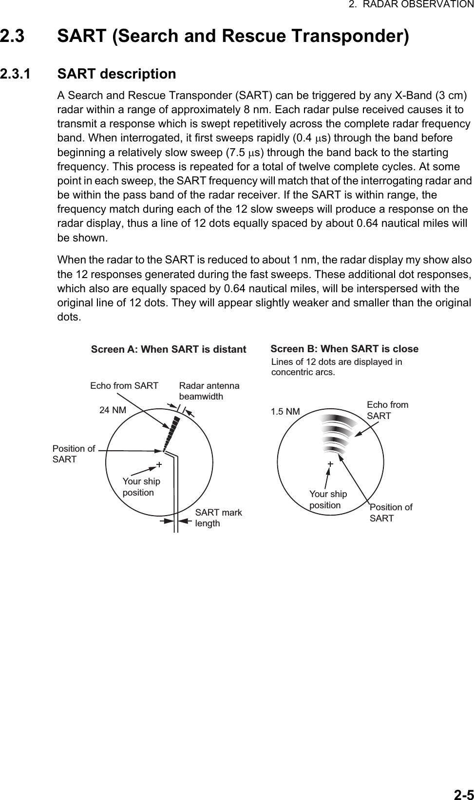
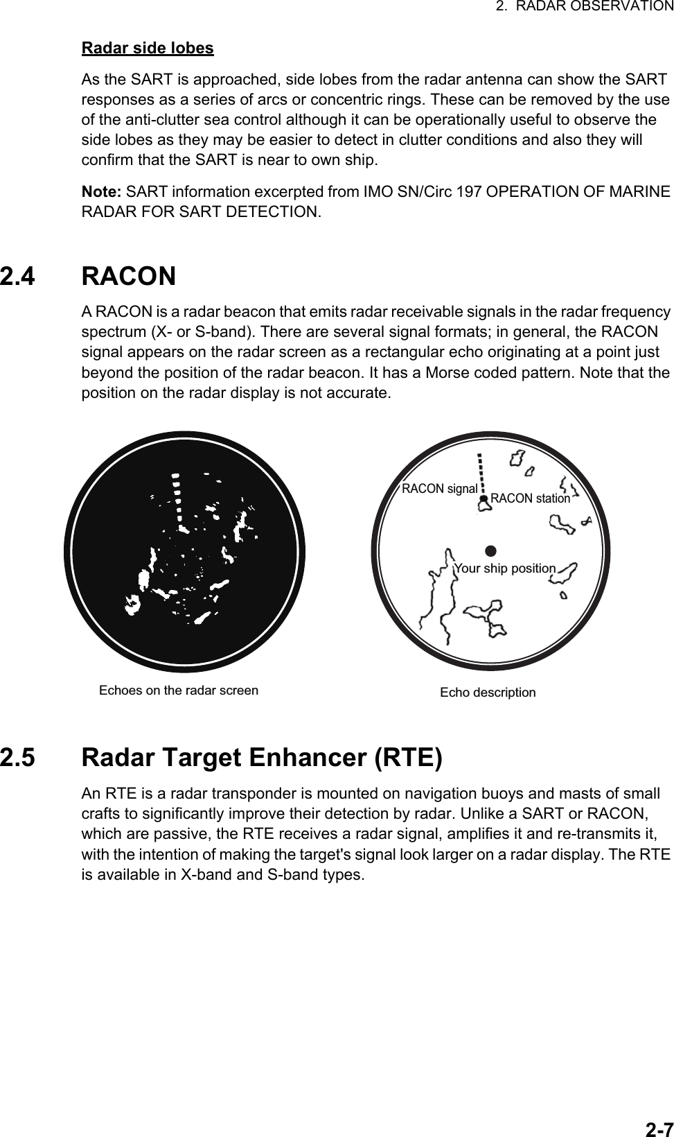
![2. RADAR OBSERVATION2-62.3.2 How to show SART marks on the radar displayThis radar is equipped with a feature that optimally sets up the radar for SART detection. This feature automatically detunes the radar receiver out of its best tuning condition. This erases or weakens all normal radar echoes, but the SART marks are not erased because the SART response signal scans over all frequencies in the 9 GHz band. When the radar approaches the SART in operation, the SART marks will enlarge to large arcs, blurring a large part of the screen.1. Open the [MAIN MENU].2. Select [ECHO], then press the left button.3. Select [SART], then press the left button.4. Select [ON] to show SART marks on the radar display, then press the left button. Select [OFF] to hide SART marks.When the SART function is active, the following setting changes are automatically made to radar functions:5. Close the menu.The indication "SART" appears at the bottom of the alert box, in yellow text, when this feature is active. Be sure to turn this feature off when SART detection is no longer your objective.2.3.3 General remarks on receiving SARTsSART range errorsWhen responses from only the 12 low frequency sweeps are visible (when the SART is at a range greater than about 1 nm), the position at which the first dot is displayed can be as much as 0.64 nm beyond the true position of the SART. When the range closes so that the fast sweep responses are seen also, the first of these will be no more than 150 meters beyond the true position.Radar bandwidthThis is normally matched to the radar pulselength and is usually switched with the range scale and the associated pulselength. Narrow bandwidths of 3-5 MHz are used with long pulses on long range scales and wide bandwidths of 10-25 MHz with short pulses on short ranges.A radar bandwidth of less than 5 MHz will attenuate the SART signal slightly, so it is preferable to use a medium bandwidth to ensure optimum detection of the SART.Setting Changed toRange 12 NMPulselength LongEcho Stretch OffNoise Rejector OffEcho Averaging OffInterference Rejector OffPerformance Monitor OffA/C RAIN Off](https://usermanual.wiki/Furuno-USA/9ZWRTR100.User-Manual-Part-4/User-Guide-2768726-Page-15.png)
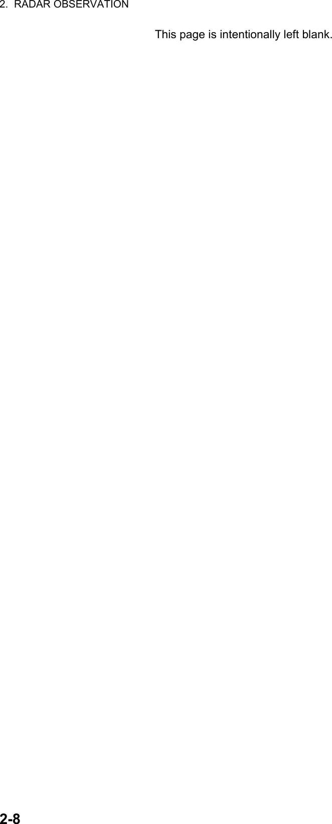
![3. TARGET TRACKING (TT)3-23.2 TT ControlsThe control unit has two keys which you can use during target tracking mode. The keys are indicated in the figure below.• TGT ACQ: Acquires the selected echo as a target.• TGT CANCEL: Deactivates tracking for the cursor-selected target.These functions, along with other TT functions, can also be accessed from the [CURSOR] menu (See section 1.7).3.3 TT Box Overview3.4 How to Select the TT modeTarget tracking is available in three modes: [MANUAL 50] (up to 50 targets, selected manually), [MANUAL 25•AUTO 25] (up to 50 targets, 25 selected automatically, 25 selected manually) and [AUTO 50] (up to 50 targets, selected automatically). To select a target tracking mode, do the following:1. Select the [TT] box, then press the right button. The [TT TARGET MENU] is displayed.2. Select [TT SELECT], then press the ADJUST knob.3. Select the appropriate mode, then press the ADJUST knob.4. Close the menu.No. Indication name Description/remarks1 TT acquisition mode Shows current TT mode (AUTO, AUTO/MAN, MAN)2 Vector time Adjusts the vector time for the selected target3 Vector reference True, Relative referencing for this target’s vector4 Past position time Sets the interval for the target’s trail5 Lost TGT Alert Display/hide the alert when a target is lostManual target acquisition Cancel target15432](https://usermanual.wiki/Furuno-USA/9ZWRTR100.User-Manual-Part-4/User-Guide-2768726-Page-19.png)
![3. TARGET TRACKING (TT)3-33.5 How to Activate/Deactivate Target TrackingPlace the cursor on the TT acquisition mode indicator, then press the left button. The indication changes, depending on the TT mode selected (See section 3.4). The table below shows the indication changes based on mode selection.The plotting symbol is drawn by broken lines during the initial acquisition stage. A vector appears in about one minute after acquisition indicating the target's motion trend. If the target is consistently detected for three minutes, the plotting symbol changes to a solid circle. If acquisition fails, the target plotting symbol blinks and disappears shortly.3.5.1 How to manually acquire targetsManual target acquisition can be done with one of two methods:Using the control unit1. Place the cursor on the target to be acquired.2. Press the key.Using the menu1. Select the operational display area, then press the right button. The [CURSOR] menu is display.2. Select [TARGET DATA/ACQ], then press the ADJUST knob.3. Place the cursor on the target to be acquired, then press the ADJUST knob.Note 1: For successful acquisition, the target to be acquired should be within 0.1 to 24 nm (or 32 nm, depending on initial setting) from own ship and not obscured by sea or rain clutter.Note 2: When the capacity for manual acquisition is reached, the message "TT TAR-GET FULL(MAN)" is displayed at the screen bottom. Cancel tracking of non-threatening targets if you wish to acquire additional targets manually.TT mode selected Indication change[Manual 50] "OFF" "MAN" "OFF"...[MANUAL 25•AUTO 25] "OFF" "MAN/AUTO" "OFF"...[AUTO 50] "OFF" "AUTO" "OFF"...At acquisition Within 1 min. after acquisition Within 3 min. afteracquisitionVectorCAUTIONCAUTIONTarget SwapWhen a target being tracked nears another target being tracked, the targets may be "swapped". When two targets acquired either automatically or manually come close to each other, one of the two may become a Lost Target. Should this happen, manual re-acquisition of the Lost Target may be required after the two have separated.](https://usermanual.wiki/Furuno-USA/9ZWRTR100.User-Manual-Part-4/User-Guide-2768726-Page-20.png)
![3. TARGET TRACKING (TT)3-43.6 How to Enter Own Ship SpeedThe TT requires own ship's speed and heading data. The speed can be STW, SOG or echo-referenced speed (based on 3 max. stationary objects). Manual input is also possible.For automatic or manual input, see section 1.12. For echo-referenced speed input follow the procedure below.3.6.1 Echo-referenced speed inputThe use of echo-referenced speed is recommended when:• The speed log is not operating properly or not connected to the radar.• The vessel has no device (doppler sonar, speed log, etc.) that can measure ship's bow-stern, port-starboard movement.If you select echo-referenced speed, the TT calculates own ship's speed relative to a fixed reference target. The number of targets may be R1, R2 or R3. When a plural of objects are selected, the mean value is used, for stabilization and speed.1. Select the operational display area, then press the right button. The [CURSOR] menu is displayed.2. Select [REF MARK], then press the ADJUST knob. The cursor is highlighted.3. Place the cursor on the location to be used as a reference, then press the ADJUST knob. The cursor changes from the highlighted cross to a circle with dashed lines, indicating that the reference location is now set. See section 3.8 for more information on TT symbols and their attributes.The dashed lines of the reference point change to a solid line over time, as shown in the figure above.](https://usermanual.wiki/Furuno-USA/9ZWRTR100.User-Manual-Part-4/User-Guide-2768726-Page-21.png)
![3. TARGET TRACKING (TT)3-5Notes on speed input by reference target• Reference targets are only used for the calculation of true speed.• Do not use reference target generated true speed to calculate relative speed. Relative speed data is not accurate because response to speed change is slow, hampering the TT's ability to accurately judge the possibility of collision.• Select a stationary target as a reference target to calculate own ship speed as ground tracking speed. Do not choose a moving target as a reference target. A moving target produces error in the vector for TT and AIS, which results in wrong collision avoidance information. Further, an unstable stationary target produces inaccurate speed data and the target itself may become lost.• When a reference target is lost or goes out of the acquisition range, that reference target mark blinks and the indication "REF TARGET LOST" appears in the alert box. If all reference targets are lost, the speed indication reads "*.*" Select a different reference target if currently selected one is lost.• When all targets are deleted, the reference target mark is also deleted and the target-based speed becomes invalid. The speed is indicated as "BTREF" where BT means Bottom Track (speed over ground).• Reference targets can be marked with a vector.This can be done with [REF TARGET VECTOR] on the [TT TARGET] menu.• Loss of reference target will affect the calculation of true speed and true course of targets. Further, own ship speed will be inaccurate.How to cancel echo-referenced speed input1. Open the [MAIN MENU].2. Select [SHIP SPEED MENU], then press the ADJUST knob.3. Select [SHIP SPEED], then press the ADJUST knob.4. Select any option, other than [REF] or [MANUAL], then press the ADJUST knob.5. Close the menu.](https://usermanual.wiki/Furuno-USA/9ZWRTR100.User-Manual-Part-4/User-Guide-2768726-Page-22.png)
![3. TARGET TRACKING (TT)3-63.7 Lost TargetTargets not detected in five consecutive scans become “lost targets”. A lost target is shown in the display with flashing red "X". Flashing stops after lost target alert is acknowledged.If you are in an area where tracked targets are lost frequently you may want to disable the lost target alert against tracked targets by maximum range or minimum speed.3.7.1 How to set the lost target filterYou can set the lost target alert to sound against lost targets that are within a specific range. To set the criteria, use the procedure below.1. Open the [MAIN MENU].2. Select [TT•AIS], then press the ADJUST knob.3. Select [TT LOST FILTER], then press the ADJUST knob.4. Select [MAX RANGE], then press the ADJUST knob.5. Select [ON], then press the ADJUST knob. The settings can now be adjusted.6. Rotate the ADJUST knob to adjust the setting as required, then press the ADJUST knob to apply the setting.7. Close the menu.Note: Reference targets are not affected by this filter.3.7.2 How to enable/disable the lost target alertThe [LOST TARGET ALERT] box at the bottom right corner enables and disables the lost target alert. Select the box with the cursor, then press the left button to select [OFF], [ALL] or [FILT] as appropriate.• [OFF]: Disable the alert.• [ALL]: Enable the alert for all lost targets, including filtered targets.• [FILT]: Enable the alert for all lost targets, excluding filtered targets.Lost target alert box](https://usermanual.wiki/Furuno-USA/9ZWRTR100.User-Manual-Part-4/User-Guide-2768726-Page-23.png)
![3. TARGET TRACKING (TT)3-73.8 TT Symbols and Attributes3.8.1 TT symbols3.8.2 How to adjust symbol brilliance1. Place the cursor on the [BRILL] box, then press the right button. The [BRILL] menu is displayed.2. Select [TT SYMBOL], then press the ADJUST knob. The settings can now be adjusted.3. Rotate the ADJUST knob to select the desired brilliance, then press the ADJUST knob to apply the setting.4. Close the menu.skrameRsutatSlobmySmetIInitial stage Broken circle around an echo to indicate the target under acquisition and initial stage of tracking, before steady-state tracking. Within one minute after acquisition (vector still unreliable). Steady tracking Solid circle with vector indicating steady state tracking (within three minutes after acquisition). (flashing) CPA alarm Plotting symbol (red) flashes to indicate the target is predicted to come into CPA or TCPA. CPA alarm acknowledge Shown in red, and flashing stops after CPA/TCPA alarm is acknowledged. Automatically acquired targets (flashing) Lost target A red X is crossed through the TT symbol to indicate that it is a lost target. Flashing stops after lost target alert is acknowledged. Manually acquired targets (the width of the line for "steady tracking" TT is thicker than that of the auto- matically acquired target) Acquisition zone (flashing) On target passing through operator-set acquisition zone Symbol is red and flashing. Target selected for data readout On selected target Target data (range, bearing, course, speed, CPA, TCPA, BCR, BCT, etc.). Reference target RAfter three minutes, changes to R On reference target Used to calculate own ship’s over-the-ground speed (echo-referenced speed) for ground stabilization.](https://usermanual.wiki/Furuno-USA/9ZWRTR100.User-Manual-Part-4/User-Guide-2768726-Page-24.png)
![3. TARGET TRACKING (TT)3-83.8.3 How to set the symbol color1. Open the [MAIN MENU].2. Select [TT•AIS], then press the ADJUST knob.3. Select [TT•AIS SYMBOL], then press the ADJUST knob.4. Select [SYMBOL COLOR], then press the ADJUST knob. The settings can now be adjusted.5. Select the appropriate color, then press the ADJUST knob.6. Close the menu.3.9 How to Display/Remove Target DataThe TT mode provides the full functionality of TT as required by the IMO Resolution A.823(19) and IEC 62288, including display of range, bearing, course, speed, CPA and TCPA of all tracked targets.The target bearing is shown in relative bearing in the HEAD UP mode and true bearing in the COURSE UP, NORTH UP and True Motion modes, with the suffix "R" (Relative) or "T" (True).The target speed and course are shown as speed over the ground or speed through the water depending on speed source.3.9.1 How to display target dataPlace the cursor on a desired tracked target and press the key. The target’s shape changes to a square and the selected TT target’s data is shown in the data display area.You can display the target data for two targets in one data box and the data for as many as six targets can be displayed.Indication DescriptionBRG Bearing from own ship to target in relative (R) or True (T) reference.RNG Range from own ship to target.T COG Relative (R) or True (T) Course Over Ground of target.Displayed as "T CTW" where speed input is set to [LOG(WT)].Displayed as "R CRS" where speed data is not available.T SOG Relative (R) or True (T) Speed Over Ground of target.Displayed as T STW where speed input is set to [LOG(WT)]. Displayed as R SPD where speed data is not available.CPA Closest Point of Approach of target to own ship.TCPA Time to CPA of target to own ship.BCR Bow crossing range of target.BCT Bow crossing time of target.](https://usermanual.wiki/Furuno-USA/9ZWRTR100.User-Manual-Part-4/User-Guide-2768726-Page-25.png)
![3. TARGET TRACKING (TT)3-93.9.2 How to remove target dataPlace the cursor on a desired tracked target and press the key. The select target’s data is no longer displayed in the data display area.3.9.3 How to display, hide and sort the target listThe target list provides a comprehensive data display of all TT (and AIS) targets being tracked.How to display/hide the target list1. Select the [Target List] menu item at the bottom-right of the screen, then press the left button. The target list is displayed inside the information box.2. Select the [Target List] menu item at the bottom-right of the screen, then press the left button to hide the target list.How to sort the target list1. With the target list displayed, select [Sort by], then press the ADJUST knob.2. Select the sort method, referring to the table below, then press the ADJUST knob.3. Select the appropriate filter option, if required, then press the ADJUST knob.Note: Targets with no data are sorted to the back of the list, regardless of filter setting.Sort method Description[CPA] Targets are sorted in order from closest to farthest CPA.[TCPA] Targets are sorted in order from shortest to longest TCPA.[BCR] Targets are sorted in order from closest to farthest BCR.[BCT] Targets are sorted in order from shortest to longest BCT.[RANGE] Targets are sorted in order from closest to farthest range.[SPEED] Targets are sorted in order from fastest to slowest.[NAME] Targets are sorted in Alphabetical order. Unknown names are displayed last.[TARGET LIST (1/2)]SORT BY CPA1 BACK(L=TOP)2 AIS TARGET NAME NAME FURUNOMARU BRG 232.8°R RNG 2.19NM CPA 0.13NM TCPA -05:343 TT TARGET NO.4 BRG 049.6°R RNG 0.75NM CPA 0.16NM TCPA> 99:599 REFRESH DATA0 NEXT (L=LAST)Target detailsSorting method](https://usermanual.wiki/Furuno-USA/9ZWRTR100.User-Manual-Part-4/User-Guide-2768726-Page-26.png)
![3. TARGET TRACKING (TT)3-103.10 Vector ModesTarget vectors can be displayed relative to own ship’s heading (Relative) or North (True).Note: IMO recommends the use of true vector mode in sea stabilization or relative vector mode for collision avoidance.To change the vector mode, do the following:Place the cursor on the vector reference indication in the [Vector] box, then press the left button. The vector reference cycles through the following settings with each press of the left button.[REL] [TRUE-G/TRUE-S] [REL]...3.10.1 Description of vectorsStabilization modesIt is important to select the optimum stabilization mode for the radar display. To assess risk of collision the relative motion of a target gives the clearest indication of CPA and may be monitored by observing either the direction of the target's relative trail, or the CPA predicted by the relative vector. By default, relative motion displays relative target trails and true motion displays true target trails. Where true target trails is selected, a sea stabilized display will indicate all targets' motion through the water. A ground sta-bilized display will indicate all targets' motion over the ground.In coastal, estuarial and river waters where a significant set and drift may be experi-enced, a sea stabilized display will produce significant target trails from all fixed (sta-tionary) objects possibly producing an unacceptably high level of clutter and masking. In such circumstances a ground stabilized display may reduce its effect and enable the observer to detect clearly the trails of moving targets, thus enhancing the observ-er's situational awareness.However, the display should be considered only as an approximation of the course and speed made good over the ground. Among other factors, the accuracy of the ground-stabilization is affected by inaccuracies in speed and heading inputs as well as radar measurement imprecision and will require the display to be readjusted peri-odically. The information displayed should be interpreted with due regard to these fac-tors.Note: It should be noted that in determining a target's aspect by radar; the calculation of its true track is dependent on the choice and accuracy of the own ship's course and speed input. A ground-stabilized target plot may accurately calculate the ground track of the target, but the target's heading may be significantly different from its track when experiencing set, drift or leeway. Similarly, a sea stabilized target plot may be inaccu-rate when own ship and the target, are experiencing different rates of set, drift or lee-way.](https://usermanual.wiki/Furuno-USA/9ZWRTR100.User-Manual-Part-4/User-Guide-2768726-Page-27.png)
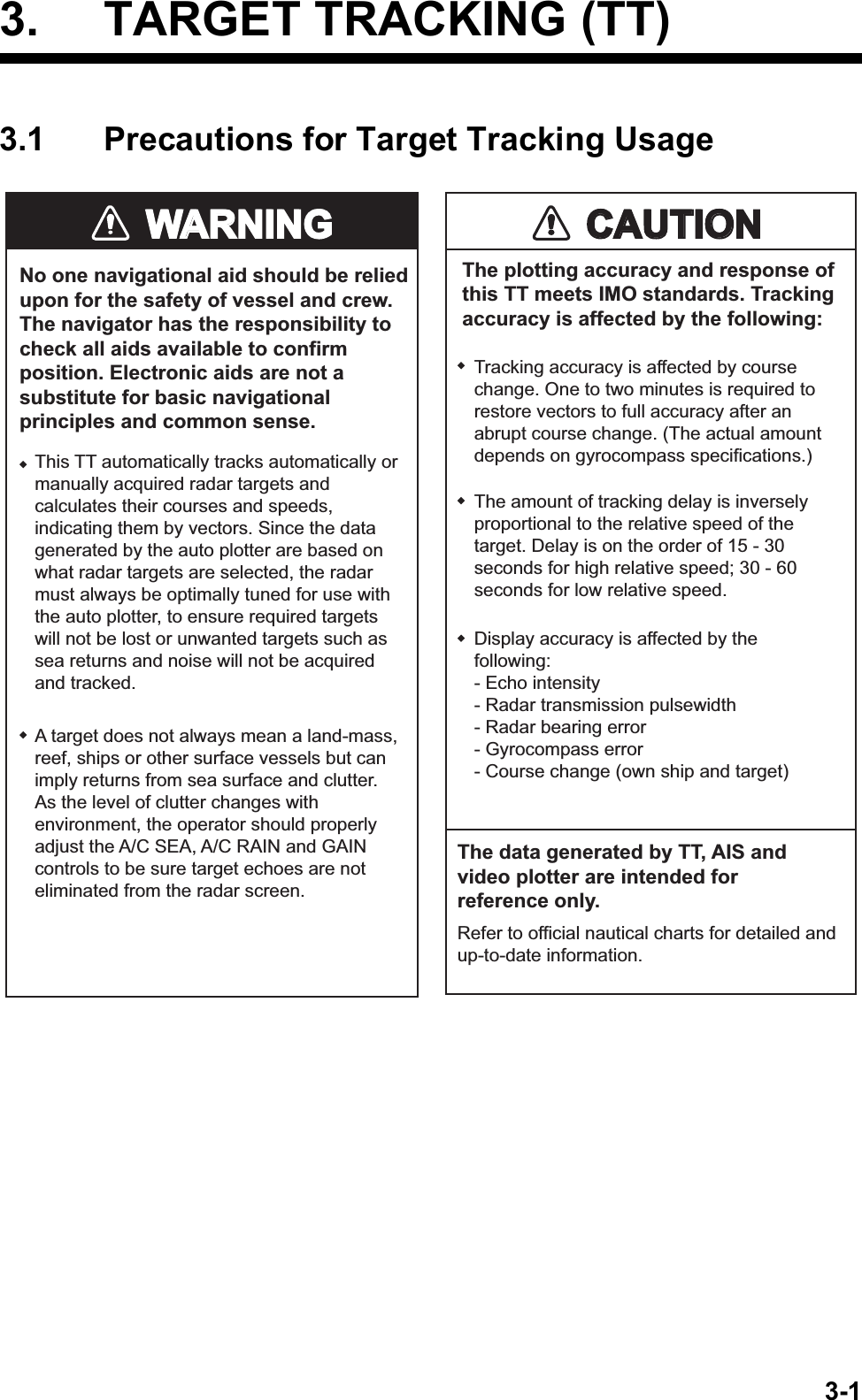
![3. TARGET TRACKING (TT)3-11Ground stabilization and sea stabilizationTarget vectors can be ground stabilized or sea stabilized in the True Motion mode. To select speed over the ground or speed through the water data, open the page from the menu. Select for ground stabilization or for sea stabilization. The Vector mode indica-tion shows the stabilization mode in the true motion as [TRUE-G] or [TRUE-S].Sea stabilization is a mode where own ship and all targets are referenced to the sea using a compass heading and single-axis log water speed inputs in the true motion mode. Ground stabilization is a mode where own ship and all targets are referenced to the ground using the ground track or set and drift inputs. If the accuracy seems un-satisfactory, enter set and drift corrections. Note that set and drift should not be used when the radar is displaying AIS targets.True vectorIn the true motion mode, all fixed targets such as land, navigational marks and ships at anchor remain stationary on the radar screen with vector length zero. But in the presence of wind and/or current, the vectors appear on fixed targets representing the reciprocal of set and drift affecting own ship unless set and drift values are properly entered.In the true vector mode, there are two types of stabilization: ground stabilization (TRUE-G) and sea stabilization (TRUE-S). The stabilization mode is automatically se-lected according to speed selection, as shown in the table below. Manual selection is available from the [SPD] menu at the top-right of the screen.Relative vectorRelative vectors on targets that are not moving over the ground such as land, naviga-tional marks and ships at anchor will represent the reciprocal of own ship's ground track. A target whose vector passes through own ship is on a collision course. (Dotted lines in the figure are for explanation only.)Speed selection True vector modeLOG(WT) TRUE-SLOG(WTC) TRUE-GLOG(BT) TRUE-GGPS(BT) TRUE-GREF(BT) TRUE-GMAN(WT) TRUE-SMAN(WTC) TRUE-GBuoyOwn ShipTrue vectors in ground stabilizationAISBuoyOwn ShipTrue vectors in sea stabilizationTTAISTTBuoyOwn ShipRelative vectorsAISTTCurrent(Set and drift)](https://usermanual.wiki/Furuno-USA/9ZWRTR100.User-Manual-Part-4/User-Guide-2768726-Page-28.png)