Furuno USA 9ZWRTR088B Transceiver for Radar model FR-8045 User Manual
Furuno USA Inc Transceiver for Radar model FR-8045
UserManual.wiki
>
Furuno USA
>
9ZWRTR088B User Manual
>
User Manual II Part 1
Contents
1.
Internal Photos
2.
User Manual I Part 1
3.
User Manual I Part 2
4.
User Manual II Part 1
5.
User Manual II Part 2
6.
User Manual II Part 3
User Manual II Part 1
Navigation menu
Upload a User Manual
Namespaces
Wiki Guide
HTML
PDF
Info
Views
User Manual
Discussion / Help
Navigation
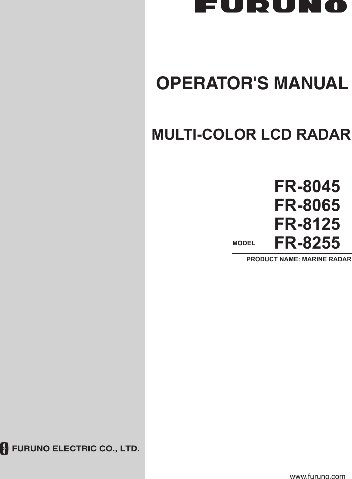
![ii SAFETY INSTRUCTIONSWARNINGRadio Frequency Radiation HazardWARNINGIndicates a condition that can cause death or serious injury if not avoided.CAUTIONIndicates a condition that can cause minor or moderate injury if not avoided. Warning, Caution Mandatory ActionProhibitive ActionRead these safety instructions before you operate the equipment. The radar antenna sends the electromagnetic radio frequency (RF) energy. This energy can be dangerous to you, especially your eyes. Do not look at the radiator or near the antenna when the antenna is rotating.The distances at which RF radiation levels of 100 W/m2 and 10 W/m2 exist are shown in the table.Note: If the antenna unit is installed at a close distance in front of the wheel house, prevent the transmission in that area to protect passengers and crew from microwave radiation. Set the [Sector Blanks] in the [System] menu.FR-8065100W/m210W/m2FR-8125FR-8255FR-8045ModelXN-12AXN-13AXN-12AXN-13AXN-12AXN-13AXN-12AXN-13A N/AN/AN/AN/AN/AN/A1.1m1.0m1.9m0.6m0.4m 3.1m4.6m1.7m2.1m1.9m](https://usermanual.wiki/Furuno-USA/9ZWRTR088B.User-Manual-II-Part-1/User-Guide-2264464-Page-4.png)
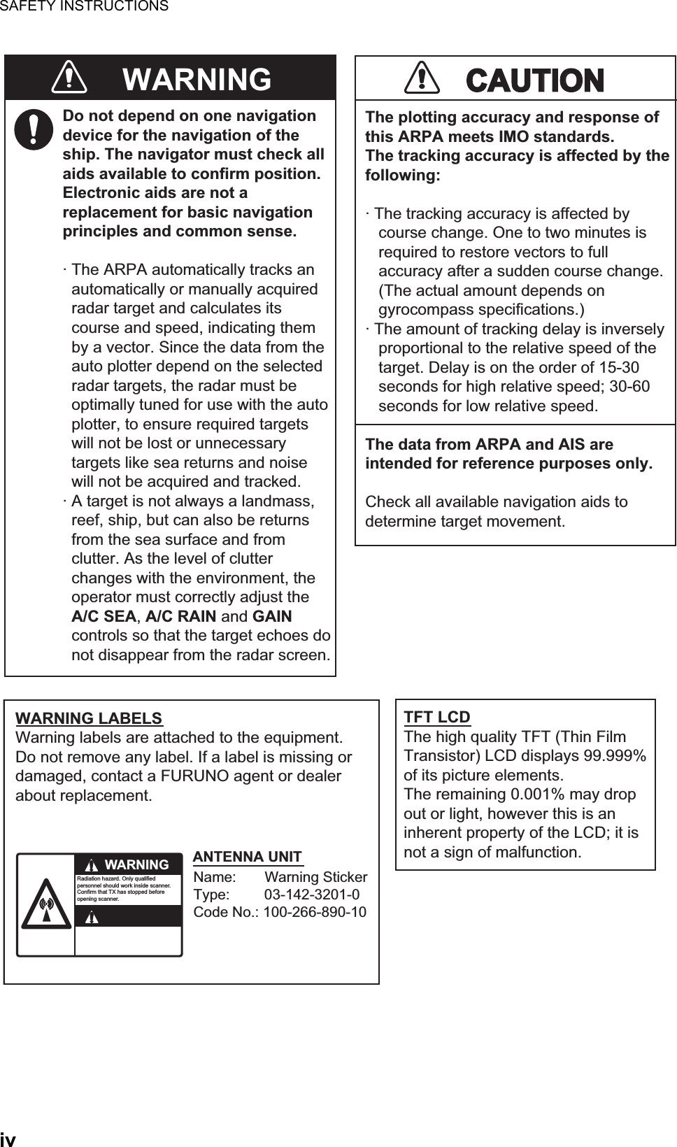
![TABLE OF CONTENTSvi1.24.7 How to restart, stop the trails ....................................................................... 1-321.24.8 Narrow trails .................................................................................................1-331.24.9 Your ship trail ............................................................................................... 1-331.25 How to Send the Target Position and Enter the Origin Mark ................................... 1-331.26 How to Hide the Heading Line Temporarily ............................................................. 1-341.27 Presentation Brilliance ............................................................................................. 1-341.28 Custom Setup .......................................................................................................... 1-341.28.1 About custom setup .....................................................................................1-341.28.2 Description of custom setup items ............................................................... 1-351.28.3 How to set custom setups............................................................................1-361.29 How to Program Function Keys (F1, F2 and F3 keys) ............................................. 1-371.30 Noise Rejector.......................................................................................................... 1-381.31 Wiper........................................................................................................................ 1-381.32 How to Reduce Second-trace Echoes ..................................................................... 1-391.33 Watchman ................................................................................................................ 1-391.34 Color Selections ....................................................................................................... 1-401.34.1 Preset colors ................................................................................................ 1-401.34.2 Custom colors .............................................................................................. 1-411.35 Navigation Data........................................................................................................ 1-421.35.1 Navigation data during standby.................................................................... 1-421.35.2 Navigation data at the bottom of the screen ................................................ 1-421.36 Dynamic Range........................................................................................................ 1-431.37 Characteristics Curve............................................................................................... 1-441.38 Waypoint Marker ...................................................................................................... 1-451.39 Alarm Message ........................................................................................................ 1-451.40 Echo Area ................................................................................................................ 1-471.41 Initial Sub Menu ....................................................................................................... 1-481.41.1 How to open the Initial sub menu................................................................. 1-481.41.2 Description of Initial sub menu..................................................................... 1-481.42 Units Sub Menu........................................................................................................ 1-501.43 Sector Blank............................................................................................................. 1-511.44 Other Menu Items .................................................................................................... 1-521.44.1 Menu items on the [Brill/Color] menu........................................................... 1-521.44.2 Menu items on the [Display] menu............................................................... 1-531.44.3 Menu items on the [Echo] menu .................................................................. 1-531.45 Remote Display........................................................................................................ 1-542. DESCRIPTION OF RADAR ...................................................................................2-12.1 General ......................................................................................................................2-12.1.1 Minimum and maximum ranges..................................................................... 2-12.1.2 Radar resolution............................................................................................. 2-22.1.3 Bearing accuracy ........................................................................................... 2-32.1.4 Range measurement......................................................................................2-32.2 False Echoes ............................................................................................................. 2-32.2.1 Multiple echoes .............................................................................................. 2-32.2.2 Sidelobe echoes............................................................................................. 2-42.2.3 Virtual image .................................................................................................. 2-42.2.4 Shadow sector ............................................................................................... 2-52.3 SART (Search and Rescue Transponder) ................................................................. 2-52.3.1 SART description ........................................................................................... 2-52.3.2 General remarks on receiving SART ............................................................. 2-62.4 RACON ...................................................................................................................... 2-6](https://usermanual.wiki/Furuno-USA/9ZWRTR088B.User-Manual-II-Part-1/User-Guide-2264464-Page-8.png)
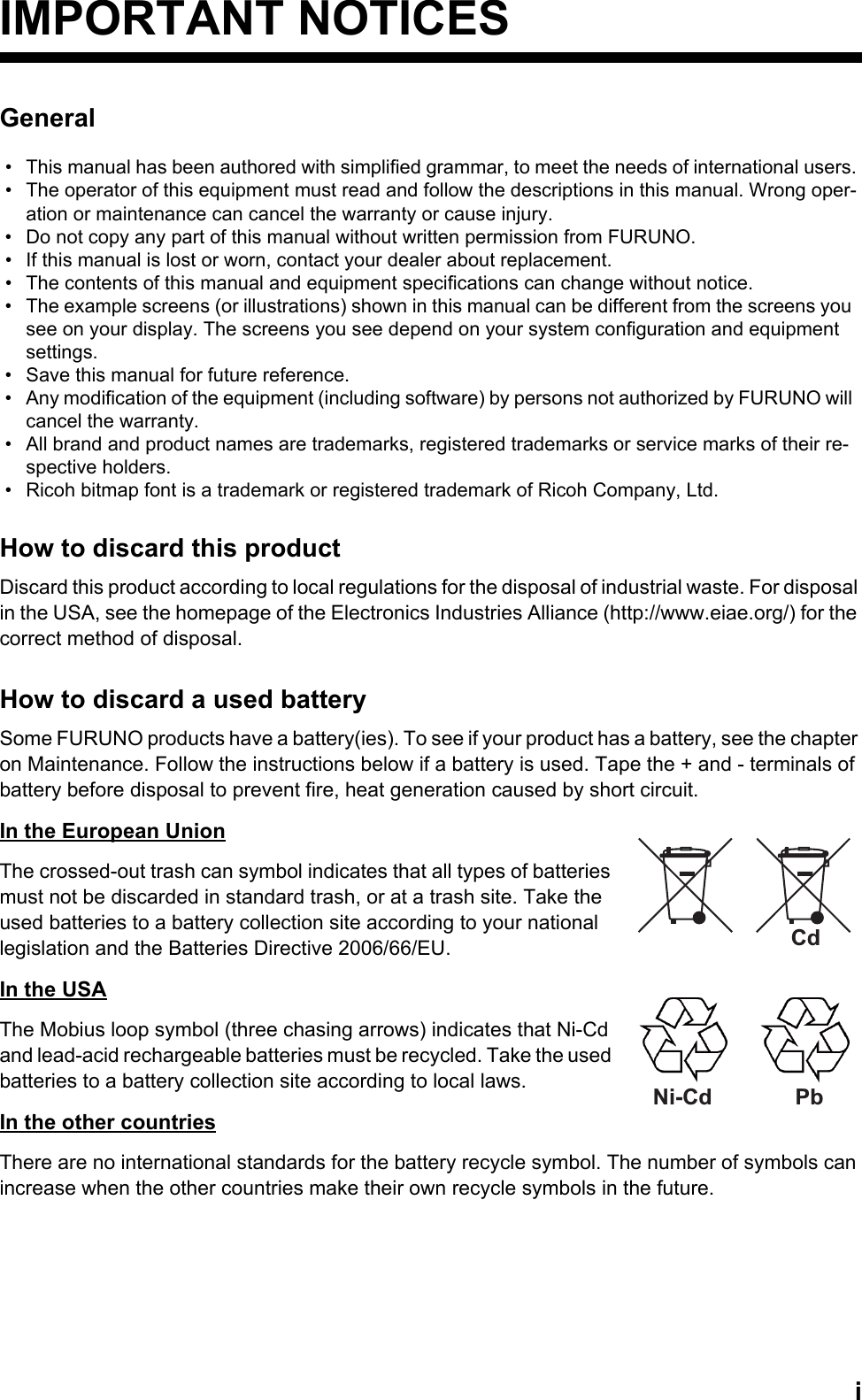
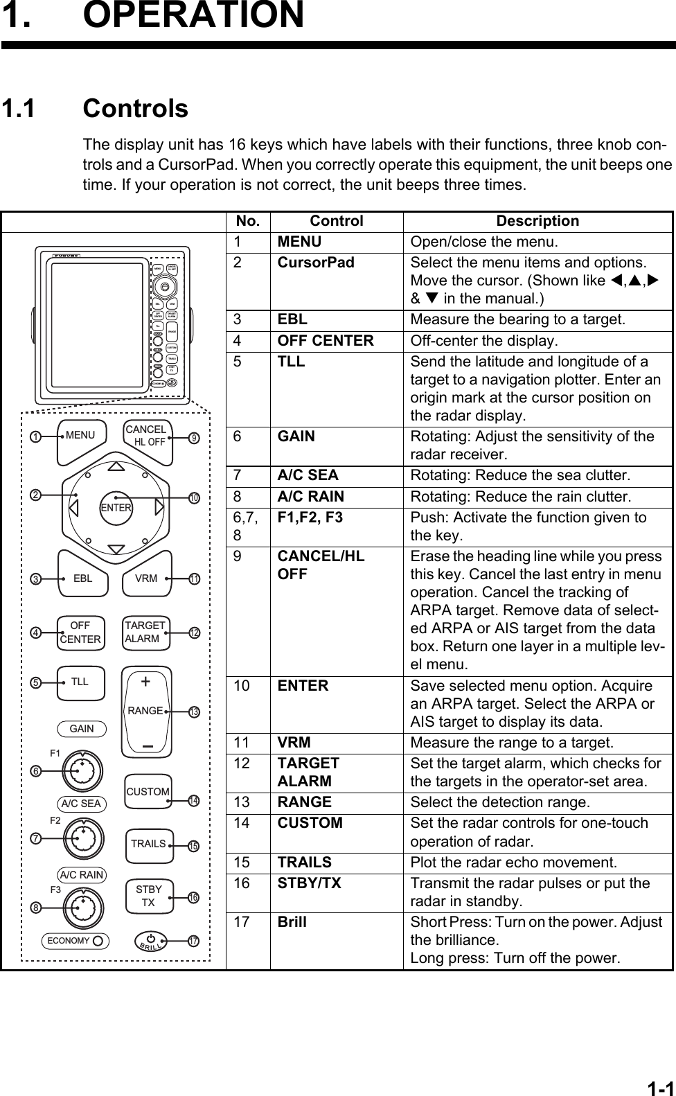
![FOREWORDxRadar Type and Function AvailabilityThis radar series is available in four types: [River], [Sea], [IEC] and [Russian-River], and function availability depends on type. The table below shows type and function availability.[River]: For river, [Sea]: For sea, [IEC]: IEC compliant radar, [Russian-River]: For Russian riverType and function availabilityItem TypeRiver Sea IEC Russian-RiverAutomatic menu closureMenu does not close automatically. Menu closes automatically when there is no menu operation for 10 seconds.Effective radius dot count300 dots 262 dotsEcho color Select the echo display color among [Yellow], [Green], [Orange] or [Multi].Select the echo display color among [Yellow], [Green] or [Orange].Echo color cus-tomizingCan customize the echo display col-or.Can not customize the echo display color.Echo area Select the display area from [Normal] or [Full Screen].Can not select. Display area is circle only.Base text display Can show or hide the base text indi-cations.Can not hide the base text indica-tions.Range preset Select the radar ranges to use. Can not select the radar ranges to use.Unit defaults 1) range 2) speed1) KM 2) km/h, m/s1) NM 2) kn 1) KM 2) km/h, m/sBearing scale Graduation every 1°, 5°, 10°, 30°, no numeric indication, displayed in the effective radiusGraduation every 1°, 5°, 10°, 30°, nu-meric indication every 30°, displayed out of the effective radiusVRM unit Can set the VRM unit independently from the range unit.Can not set the VRM unit indepen-dently from the range unit.Range unit Can change the range unit when transmitting.Can not change the range unit in transmit. Only in standby.AIS symbol color Select the AIS symbol color from [Green], [Red], [Blue], [White] or [Black].Select the AIS symbol color from [Green], [Blue], [White] or [Black].Vector reference Select the display mode for the vector from [Relative] or [True].[True]Pulselength • 2NM/4KM/2SM: MP• 4NM/8KM/4SM: LP• 2NM/4KM/2SM: SP or MP• 4NM/8KM/4SM: MP or LPThe rule for the numbering of ARPA targetsNon-IEC system IEC systemMarks temporary hidden by press-ing and holding the CANCEL/HL OFF keyHeading line, all marks (EBL, VRM, target alarm zone, etc.)Heading line, vector of your ship (with ARP-11)](https://usermanual.wiki/Furuno-USA/9ZWRTR088B.User-Manual-II-Part-1/User-Guide-2264464-Page-12.png)

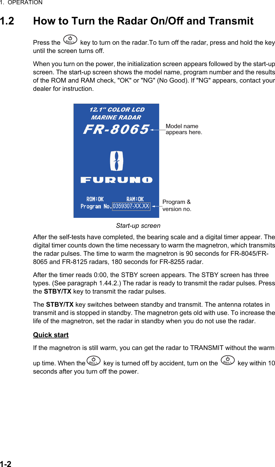
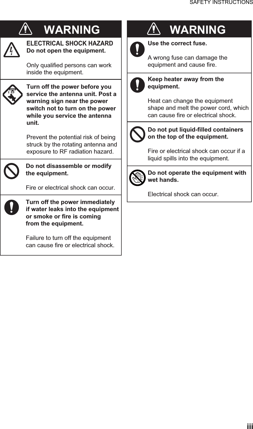
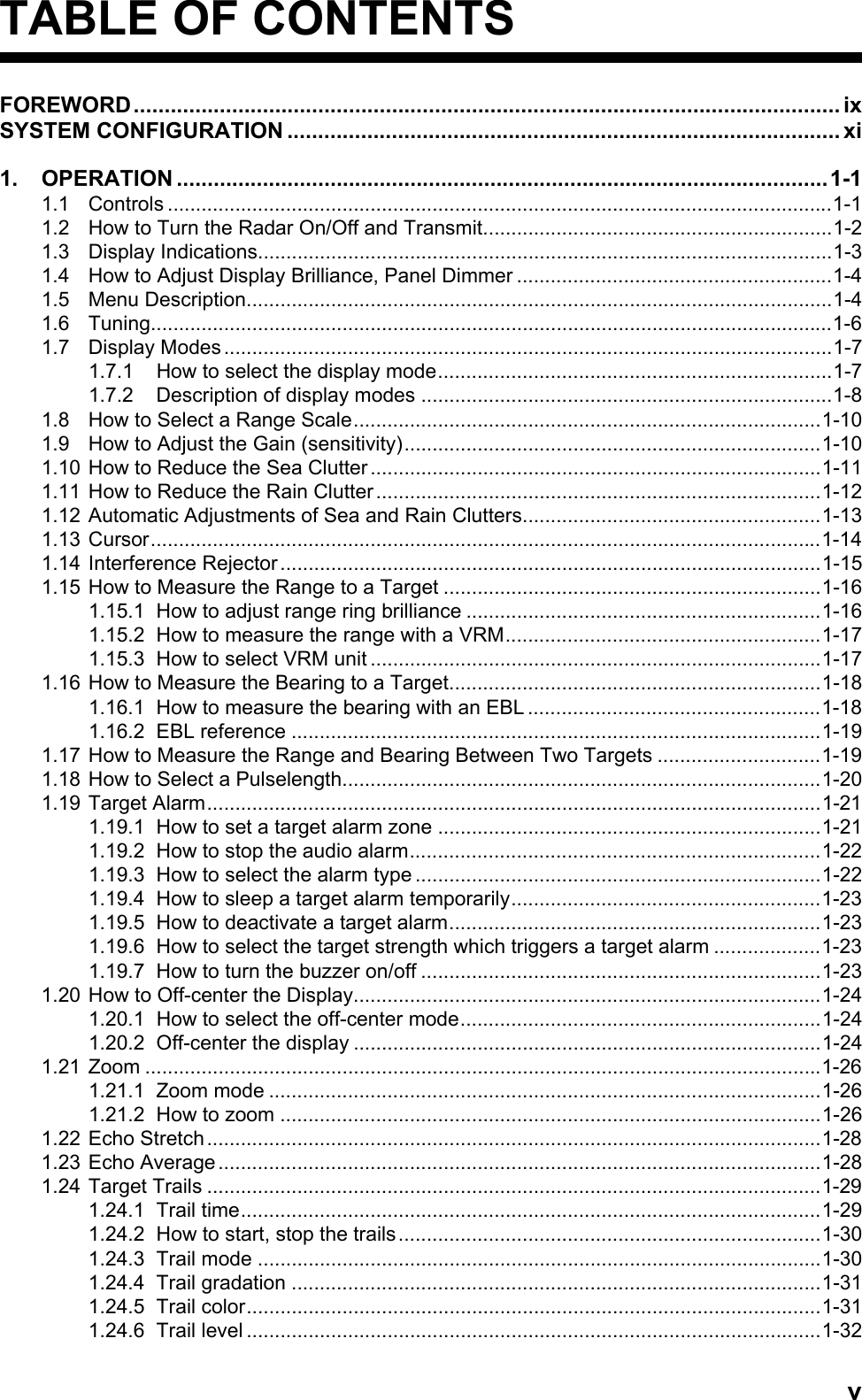
![1. OPERATION1-31.3 Display IndicationsDisplay indicationsHeadingNav data: Appears at screen bottom when [Data Box]in the [Display] menu is set to [Nav] or [All]. Appropriatesensors required to display nav data.Cursor data(Range and bearing or L/L position)Display modeRange ring intervalRangePulselength Trail referenceNo. 1 EBL bearingNo. 2 EBL bearingOffcenter(M: Manual, A: Auto, C: Custom)North markerTuning indicatorTarget Alarm 1 (2)indicationsNo. 1 VRM rangeNo. 2 VRM rangeWATCHMANTarget alarm zone 1Target alarm zone 2350.0°TRAIL(T)15 S +1.51.5NMNMOFFCENT(A) WTCHeading lineRange ringNo. 2 VRMNo. 2 EBLZoom windowZoom cursorNo. 1 EBLNo. 1 VRMCursorBearing scaleHDG0.5SP CS 1 Custom setting(1 - 3)H UP LAT 34°56.123NLON 135°34.567ESPEED 12.3KNLAT 34°56.123NLON 135°34.567ETTG 01:00B RG 14. 8°RNG 0.876NMTTG 00:20OWN SHIP + CURSOR WAYPOINTTUNEAUTOALM1_ACKALM2_OUTSLAVEInput source(shown when display unit functions as remote display)IR 1A/C AUTOVRM0.889NM0.422NMInterference rejectorAuto adjustment ofrain and sea clutters22.0°R270.0°RES 1EAV 1EBLEcho stretchEcho averaging241.0°R 1.592NMVECT TRUE 05:00Vector timeZOOM(R) Zoom indication+Trail time](https://usermanual.wiki/Furuno-USA/9ZWRTR088B.User-Manual-II-Part-1/User-Guide-2264464-Page-17.png)
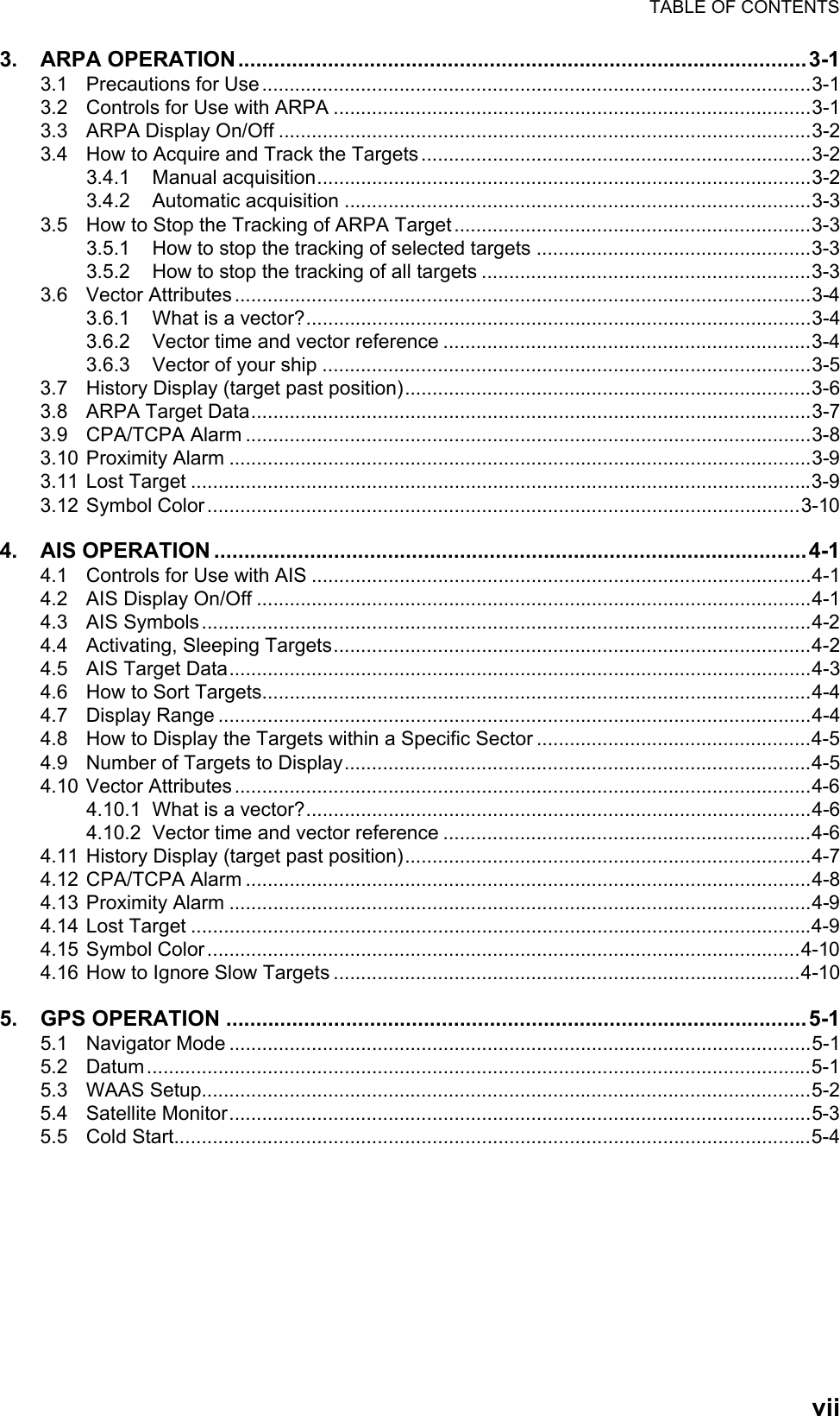
![1. OPERATION1-41.4 How to Adjust Display Brilliance, Panel DimmerYou can adjust the display brilliance and panel dimmer as follows:1. Press the key to show the [Brill/Panel] dialog box.Brill/Panel dialog box2. Press the [ENTER] key (or S, T) to select [Brill] or [Panel].3. Use W or X to adjust. (For brilliance you can also use the key.)4. Press the CANCEL/HL OFF key to close the window.1.5 Menu DescriptionThis FR-8045/FR-8065/FR-8125/FR-8255 series has 15 menus and 6 sub menus. Below is the basic procedure for menu operation.1. Press the MENU key to open the menu.MenuBRILL Brill/PanelMin MaxBrill (1~16)168Panel (1~ 8)Enter SelectCANCEL/HL OFFCloseBRILL Cursor*Menu itemsand currentsettingsTitle bar**: Title bar in currently controlled column is blue; cursor selection is yellow. Title bar of inactive column is gray.Brill/ColorDisplayEchoCustom 1Custom 2Custom 3AlarmTarget TrailsTuningOthersTargetMenu Brill/ColorEcho BrillRings BrillMark BrillHL BrillCharacter BrillEcho ShadingDisplay ColorEcho ColorBackground Color: 8: 4: 4: 4: 4: 1: Custom: Yellow: Black[ENTER]: Enter[MENU] Exit[CANCEL/HL OFF]: BackAdjusting brilliance and colorMenu Currently selected menuScroll bar (Indicates menus currently not shown in menuwindow. Black vertical line indicates location in menu.You can see the menus and sub menus currently not shownby using or .)Guide message(The simple explanation for the current menu.)](https://usermanual.wiki/Furuno-USA/9ZWRTR088B.User-Manual-II-Part-1/User-Guide-2264464-Page-18.png)
![1. OPERATION1-52. Use S or T to select a menu or sub-menu.The cursor (yellow) in the [Menu] col-umn indicates the menu currently selected. The menu items in the right-hand win-dow change according to the menu selected.Menu Description[Brill/Color]: Adjust the brilliance and color.[Display]: Set up the display features.[Echo]: Adjust the radar echo.[Custom 1] - [Custom 3]: Adjust the user settings.[Alarm]: Set up the alarm features.[Target Trails]: Process the trails of radar targets.[Tuning]: Adjust the radar tuning.[Others]: Set up other items.[Target]: Set up the targets configuration.[ARPA]: Set up the ARPA targets.[AIS]: Set up the AIS targets.[GPS]: Set up the GP-320B (Black-Box GPS).[System] [Initial]: Initial Setting. [Tests]: Diagnostic self test, LCD test and ARPA test. See section 6.7 to 6.9. [Sector Blanks]: Set sector blanks to prevent the transmission in a certain area. [Units]: Set up units. [Installation] and [Factory]: For use by the installer. See Installation Manual.3. Press the ENTER key to switch the cursor to the menu items column. The cursor in the menu column now turns gray and the cursor in the menu items column is yellow. The control moves to the menu items column.To switch the cursor from the menu items column to the menu column, use the CANCEL/HL OFF key. The color of the title bar of the active column is blue and of the inactive column in gray.4. Use S or T to select a menu item and press the ENTER key. A window with op-tions for the related menu item appears.Example windows5. Use S or T to select an option or numeric value.6. Press the ENTER key to save your selection. To close the window without saving, press the CANCEL/HL OFF key.7. Press the MENU key to close the menu.Note: The menus on the [IEC] and [Russian-River] types close automatically when there is no menu operation for 10 seconds, according to IEC regulations. The following menus and screens are excluded from this regulation: [Alarm message], [Alarm status], [Tuning Init Adjust], [GPS self test], [GPS satellite monitor], [System self test], [System LCD pattern], and [Auto installation setup]. The menus do not close automatically in the [River] or [Sea] configuration.Display Color options Echo Brill setting windowDayNightTwilightCustom8(1~8)](https://usermanual.wiki/Furuno-USA/9ZWRTR088B.User-Manual-II-Part-1/User-Guide-2264464-Page-19.png)
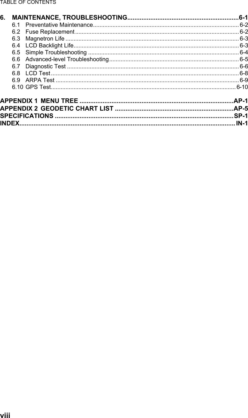
![1. OPERATION1-61.6 TuningIn default, the radar receiver can be tuned automatically after you set the radar to TX.If you require fine tuning in manual, do the following:1. Transmit the radar and select the maximum range with the RANGE key.2. Press the MENU key to open the menu.3. Use S or T to select [Tuning] and press the ENTER key.Tuning menu4. Use S or T to select [Tuning Mode] and press the ENTER key.Tuning Mode options5. Use S or T to select [Manual] and press the ENTER key.6. Use S or T to select [Manual Tuning] and press the ENTER key.Manual Tuning setting window7. Use S or T to adjust the tuning while you look at the tuning bar in the upper-right corner of the display. The best tuning point is where the tuning bar moves to a maximum value. The vertical bar on the tuning bar shows the tuning voltage.8. Press the ENTER key.9. Press the MENU key to close the menu.Note: If the automatic tuning does not give the correct tuning, run the [Tuning Init Ad-just] again.[ENTER]: Enter[MENU] Exit[CANCEL/HL OFF]: BackMenuTuningTuning Mode : AutoManual Tuning : 6.00VTuning Init AdjustBrill/ColorDisplayEchoCustom 1Custom 2Custom 3AlarmTarget TrailsTuningOthersTargetChoosing a tuning modeAutoManualTUNE MAN Tuning method (Manual)Tuning barVertical bar](https://usermanual.wiki/Furuno-USA/9ZWRTR088B.User-Manual-II-Part-1/User-Guide-2264464-Page-20.png)
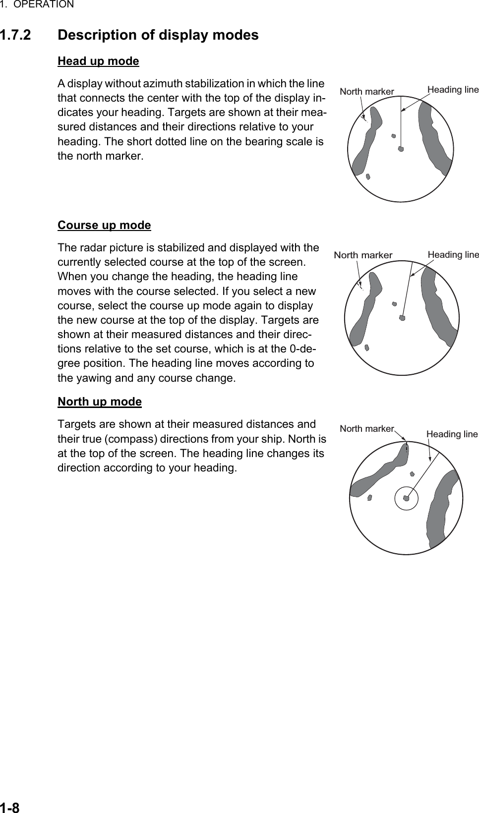
![1. OPERATION1-71.7 Display ModesThis radar has the display modes shown below. All modes except head up require a heading signal. The true motion mode additionally requires position data.Relative Motion (RM)• [Head Up] (H UP)• [Course Up] (C UP)• [North Up] (N UP)• [True View] (TRUE VIEW)True Motion• [True Motion] (TM)1.7.1 How to select the display mode1. Press the MENU key to open the menu.2. Use S or T to select [Display] and press the ENTER key.Display menu3. Use S or T to select [Display Mode] and press the ENTER key.4. Use S or T to select a display mode and press the ENTER key.5. Press the MENU key to close the menu.Note: All modes except head up require a heading signal in AD-10 format or NMEA format. If the heading signal is lost, the mode is changed to head up and the north marker disappears. The display for heading is XXX.X and the alarm sounds. The mes-sage "GYRO" (AD-10 format data) or "NMEA_HDG" (NMEA format data) appears in the alarm message display. To stop the audio alarm, press any key. When the heading signal is restored, check the heading. To check the heading, press the F3 key. When the heading signal is restored, the current heading is displayed at the heading indica-tion.Menu DisplayBrill/ColorDisplayEchoCustom 1Custom 2Custom 3AlarmTarget TrailsTuningTargetOthers[ENTER]: Enter[MENU] Exit[CANCEL/HL OFF]: BackChoosing the presentation modeDisplay Mode : Head UpZoomZoom ModeOffcenter ModeSave OffcenterEcho AreaBase Text DisplayData BoxGain/Sea/Rain Bar: Off: Relative: Normal: AllHead UpCourse UpNorth UpTrue MotionTrue View](https://usermanual.wiki/Furuno-USA/9ZWRTR088B.User-Manual-II-Part-1/User-Guide-2264464-Page-21.png)
![1. OPERATION1-9True motion modeYour ship and other objects in motion move with their true courses and speed. All fixed targets, like landmasses, ap-pear as fixed echoes in ground stabilized TM. When your ship reaches a point that is 75% of the radius of the dis-play, the position is reset. The ship appears at 75% radius opposite to the extension of the heading line on the dis-play center. You can manually reset your ship symbol if you press the OFF CENTER key.Example: Automatic reset of your ship marker in true motion modeTrue view modeThe echoes move in real time according to the change of the heading of your ship. The heading line is at the top of the screen. When the heading signal is lost, this function is not available and the display mode automatically changes to the head up mode. The [Wiper] is not available in this mode (see section 1.31).Heading linNorth markerHeadinglineNorthmarker(a) True motion is selected(b) Your ship has reached a point 75% of display radius(c) Your ship is automatically reset to 75% of display radiusHeading lineNorth marker Heading lineNorth markerThe echoes moveaccording to thechange of the headingof your ship duringone sweep.](https://usermanual.wiki/Furuno-USA/9ZWRTR088B.User-Manual-II-Part-1/User-Guide-2264464-Page-23.png)
![1. OPERATION1-101.8 How to Select a Range ScaleThe selected range scale, range ring interval and pulselength are shown at the upper left corner on the screen. When an object target comes closer, reduce the range scale so that the target appears in 50-90% of the display radius.Use the RANGE key to select range. Press the "+" part of the key to raise the range; the "-" part to lower the range.1.9 How to Adjust the Gain (sensitivity)The gain functions to adjust the sensitivity of the receiver for the best reception. The gain is adjusted automatically or manually.1. Press the MENU key to open the menu.2. Use S or T and select [Echo] and press the ENTER key.3. Use S or T to select [Gain Mode] and press the ENTER key.4. Use S or T to select [Auto] or [Manual] and press the ENTER key. the window for Gain/Sea/Rain indicator shown below appears. This window closes automatically in the [River] or [Sea] mode when there is no menu operation for ten seconds. [Auto] is for adjusting the gain automatical-ly. For [Manual] go to "Manual mode" below.Gain/Sea/Rain indicator5. Press the CANCEL/HL OFF key to close the window.6. Press the MENU key to close the menu.Note: To adjust the gain finely in [Auto] mode, rotate the GAIN knob. The confirmation message appears. If you select [Yes] the mode changes to [Manual] mode. Rotate the Gain knob to adjust the gain.Manual mode1. Rotate the GAIN knob to adjust the gain so that weak noise appears on all of the screen. If the gain is too low, weak echoes are erased. If the gain is too high, the background noise hides weak targets.2. Press the CANCEL/HL OFF key to close the window.ManualAutoGain/Sea/RainGAIN MANSEARAINMANMAN[CANCEL/HL OFF: CloseAUTO: Auto, MAN: ManualGain setting barAre you sure to change to manual mode?](https://usermanual.wiki/Furuno-USA/9ZWRTR088B.User-Manual-II-Part-1/User-Guide-2264464-Page-24.png)
![1. OPERATION1-111.10 How to Reduce the Sea ClutterThe reflected echoes from the waves appear around your ship and have the name "sea clutter". The sea clutter extends according to the height of waves and antenna above the water. When the sea clutter hides the targets, use the A/C SEA control to reduce the clutter, either manually or automatically.Auto mode1. Press the Menu key to open the menu.2. Use S or T to select [Echo] and press the ENTER key.3. Use S or T to select [Sea Mode] and press the ENTER key.4. Use S or T to select [Auto] or [Manual] and press the ENTER key. The window for Gain/Sea/Rain indicator appears. (Refer to the illustration of step 4 in section 1.9). If you selected [Auto], go to step 5. For [Manual], go to "Manual mode" below.5. Press the CANCEL/HL OFF key to close the window. [Auto] is used to reduce the sea clutter automatically. If the sea clutter is strong while cruising along a coast-line in the [Auto] mode, go to step 6. If not, go to step 9.6. Use S or T to select [Auto Sea] and press the ENTER key.7. Use S or T to select [Coastal] or [Advanced] then press the ENTER key. The win-dow for Gain/Sea/Rain indicator appears for confirmation.[Coastal]: Suppress both land and sea clutter. For cruising along a coastline.[Advanced]: Automatically identify land echoes from sea reflections to suppress only sea reflections. Use this mode for general use.8. Press the CANCEL/HL OFF key to close the menu.9. Press the MENU key to close the menu,Note: When you want to adjust the sea clutter finely in [Auto] mode, rotate the A/C SEA knob. The confirmation window appears. If you select [Yes], the mode changes to [Manual] mode. Rotate the A/C SEA knob to adjust the sea clutter.Confirmation messageManual mode1) Rotate the A/C SEA knob to reduce the sea clutter.Note: When the setting of the A/C SEA control is correct, the clutter is broken into small dots, and small targets become identified. If the setting is not enough, targets are hidden in the clutter. If the setting is higher than necessary, both sea clutter and targets disappear from the display. Normally adjust the control until the clutter has disappeared to leeward, but a small amount of the clutter is visible windward.CoastalAdvancedAre you sure to change to manual mode?](https://usermanual.wiki/Furuno-USA/9ZWRTR088B.User-Manual-II-Part-1/User-Guide-2264464-Page-25.png)
![1. OPERATION1-122) Press the CANCEL/HL OFF key to close the window.1.11 How to Reduce the Rain ClutterThe reflections from the rain or snow appear on the screen. These reflections have the name "rain clutter". When the rain clutter is strong, targets in the rain clutter are hidden in the clutter. Reflections from the rain clutter are easily identified from true targets by their wool-like appearance.The A/C RAIN control, like the A/C SEA control, adjusts the receiver sensitivity, but in longer range. If the setting is high, the rain clutter is more reduced. The rain control breaks the continuous display of rain or snow reflections into a random pattern. When the rain clutter hides the targets, adjust the rain control (au-tomatic or manual) to reduce the clutter.Auto mode1. Press the MENU key to open the menu.2. Use S or T to select [Echo] and press the ENTER key.3. Use S or T to select [Rain Mode] and press the ENTER key.4. Use S or T to select [Auto] or [Manual] then press the ENTER key. The window for Gain/Sea/Rain indicator appears (refer to the illustration of step 4 at section 1.9). If you selected [Auto], go to step 5. For [Manual], go to "Manual mode" below.5. Press the CANCEL/HL OFF key to close the window.6. Use S or T to select [Auto Rain] and press the ENTER key.7. Use S or T to select [Calm], [Moderate] or [Rough] then press the ENTER key. The window for Gain/Sea/Rain indicator appears for confirmation.[Calm]: For light rain[Moderate]: When you cannot reduce the rain clutter with [Calm] mode[Rough]: For heavy rain8. Press the CANCEL/HL OFF key to close the window.9. Press the MENU key to close the menu.Note: When you want to adjust the rain clutter finely in [Auto] mode, rotate the A/C RAIN knob. The confirmation message appears. If you select [Yes], the mode chang-es to [Manual] mode. Rotate the A/C RAIN knob to adjust the rain clutter.A/C SEA control adjusted;sea clutter reducedSea clutter atscreen centerCalmModerateRough](https://usermanual.wiki/Furuno-USA/9ZWRTR088B.User-Manual-II-Part-1/User-Guide-2264464-Page-26.png)
![1. OPERATION1-13Manual mode1. Rotate the A/C RAIN knob to reduce the rain clutter.2. Press the CANCEL/HL OFF key to close the window.1.12 Automatic Adjustments of Sea and Rain CluttersWhen you can not correctly reduce the sea clutter or rain clutter with the related con-trol, turn on the automatic anti-clutter feature. When this feature is turned on, "A/C AUTO" appears at the lower-right corner.1. Press the MENU key to open the menu.2. Use S or T to select [Echo] and press the ENTER key.3. Use S or T to select [A/C Auto] and press the ENTER key.4. Use S or T to select [Off] or [On] then press the ENTER key.5. Press the MENU key to close the menu.Caution on use• Echoes that cover wide areas (like land and islands) can become smaller when the [A/C Auto] is used.• When [A/C Auto] is active, the strength of a target in sea clutter or rain clutter can be lower than actual strength. In this case change to manual A/C SEA and manual A/C RAIN and adjust the picture.Rain clutter atscreen center A/C RAIN control adjusted;rain clutter reducedA/C Auto: Off A/C Auto: On:£:¸:Å:»Land:£:¸:Å:»Target](https://usermanual.wiki/Furuno-USA/9ZWRTR088B.User-Manual-II-Part-1/User-Guide-2264464-Page-27.png)
![1. OPERATION1-141.13 CursorThe cursor functions to find the range and bearing (default function) to a target or the latitude and longitude position of a target. Use the CursorPad to move the cursor into position and read the cursor data at the screen bottom.Cursor dataYou can show the cursor data as range and bearing (from your ship to the cursor) or latitude and longitude. Position and heading signal are required.1. Press the MENU key to open the menu.2. Use S or T to select [Others] and press the ENTER key.Others menuCursor data(range and bearing, or latitutde and longitude)110.1° R 0.488 NM NM0.5Cursor++ Brill/ColorDisplayEchoCustom 1Custom 2Custom 3AlarmTarget TrailsTuningTargetOthersMenu[ENTER]: Enter[MENU] Exit[CANCEL/HL OFF]: BackF1 SetupCursor Position : Rng/BrgF2 SetupF3 SetupWPT MarkEBL ReferenceVRM UnitTLL Key Mode: Gain Mode: Sea Mode: A/C Auto: Off: Relative: NM: TLL OutputChoosing display mode of cursor positionOthers](https://usermanual.wiki/Furuno-USA/9ZWRTR088B.User-Manual-II-Part-1/User-Guide-2264464-Page-28.png)
![1. OPERATION1-153. Use S or T to select [Cursor Position] and press the ENTER key.Cursor Position options4. Use S or T to select [Rng/Brg] (Range/Bearing) or [Lat/Lon] (Latitude/Longitude) then press the ENTER key. (When the navigation data box display is set to [Nav] or [All] in the [Display] menu, cursor latitude and longitude position cannot be dis-played in the cursor data box.)5. Press the MENU key to close the menu.1.14 Interference RejectorThe radar interference can occur when your ship is near the radar of another ship that operates on the same frequency band with your radar. The interference shows on the screen as many bright dots. The dots can be random or in the shape of dotted lines that run from the center to the edge of the display. You can identify the interference from the normal echoes, because the interference does not appear in the same loca-tion at the next antenna rotation. When this feature is turned on, "IR 1", "IR 2" or "IR 3" appears at the lower-right corner.Interference1. Press the MENU key to open the menu.2. Use S or T to select [Echo] and press the ENTER key.3. Use S or T to select [Int Rejector] and press the ENTER key.Indication at the lower-right corner of the display4. Use S or T to select [Off], [1], [2] or [3] then press the ENTER key. [3] removes the interference the most.5. Press the MENU key to close the menu.Note: When there is no interference, turn off the interference rejector so you do not miss the small targets.Rng/ BrgLat/LonOff123IR 1IR 2IR 3](https://usermanual.wiki/Furuno-USA/9ZWRTR088B.User-Manual-II-Part-1/User-Guide-2264464-Page-29.png)
![1. OPERATION1-161.15 How to Measure the Range to a TargetYou can measure the range to a target in three methods. You can use the fixed range rings, the cursor (if set to measure range and bearing) and the VRM (Variable Range Marker).Use the fixed range rings to get a rough estimate of the range to a target. The fixed range rings are the concentric solid circles about your ship. The number of rings changes with the selected range scale. The interval of the range ring is displayed at the upper-left corner of the screen. Count the number of rings between the center of the display and the target. Check the range ring interval and measure the distance of the echo from the nearest ring.1.15.1 How to adjust range ring brilliance1. Press the MENU key to open the menu.2. Use S or T to select [Brill/Color] and press the ENTER key.3. Use S or T to select [Rings Brill] and press the ENTER key.Brill/Color menu4. Use S or T to select an option and press the ENTER key. [4] is the brightest. [Off] turns off the range rings.Rings/Brill options5. Press the MENU key to close the menu.: 8: 4: 4: 4: 1: Custom: Yellow: Black[ENTER]: Enter[MENU] Exit[CANCEL/HL OFF]: BackAdjusting range ring brilliance Menu Brill/ColorEcho BrillMark BrillHL BrillCharacter BrillEcho ShadingDisplay ColorEcho ColorBackground ColorRings Brill : 4Brill/ColorDisplayEchoCustom 1Custom 2Custom 3AlarmTarget TrailsTuningOthersTargetOff1234](https://usermanual.wiki/Furuno-USA/9ZWRTR088B.User-Manual-II-Part-1/User-Guide-2264464-Page-30.png)
![1. OPERATION1-171.15.2 How to measure the range with a VRMThere are two VRMs, No. 1 and No. 2. The VRMs are dashed rings so that you can identify the rings from the fixed range rings. You can identify VRM 1 from VRM 2 by different lengths of dashes. The dashes of the No. 1 VRM are shorter than those of the No. 2 VRM.1. Press the VRM key to display either of the VRMs. Press the VRM key to change the active VRM between No. 1 and No. 2. The indication of the currently active VRM is in a rectangle.2. Use the CursorPad to align the Variable Range Marker with the inner edge of the target. Read the distance at the lower-right corner of the screen. Each VRM re-mains at the same geographical distance when you operate the RANGE key. The size of the VRM ring changes in proportion to the selected range scale.3. Press the ENTER key to anchor the VRM.4. To erase a VRM, press the VRM key to activate the VRM and press the CANCEL/HL OFF key.1.15.3 How to select VRM unitYou can select the unit of measurement used by the VRM. The selections are nautical miles (NM), kilometers (KM), statute miles (SM), kiloyard (KYD) or nautical miles and yards (NM&YD). The cursor range unit is also changed when the VRM unit is changed.1. Press the MENU key to open the menu.2. Use S or T to select [Others] and press the ENTER key.VRM 1Cursor range and bearingVRM 2Target+VRM5.044NM2.082NMCursor (+)VRM 1 rangeVRM 2 range+ The currently active VRMis in a rectangle.37.4º R 5.044 NM VECT TRUE 05:00](https://usermanual.wiki/Furuno-USA/9ZWRTR088B.User-Manual-II-Part-1/User-Guide-2264464-Page-31.png)
![1. OPERATION1-183. Use S or T to select [VRM Unit] and press the ENTER key.4. Use S or T to select the unit and press the ENTER key.5. Press the MENU key to close the menu.1.16 How to Measure the Bearing to a TargetUse the Electronic Bearing Line (EBL) to take a bearing of a target. There are two EBLs, No. 1 and No. 2. Each EBL is a straight dashed line from the center of the screen to the edge. The dashes of the No. 1 EBL are shorter than those of the No. 2 EBL.1.16.1 How to measure the bearing with an EBL1. Press the EBL key to display either of the EBLs. Press the EBL key to change the active EBL between No. 1 and No. 2. The indication of the currently active EBL is in a rectangle.2. Use the CursorPad to put the EBL on the center of the target. Read the bearing at the lower-left corner of the screen.3. Press the ENTER key to anchor the EBL.4. To erase an EBL, press the EBL key to activate the EBL and press the CANCEL/HL OFF key.How to measure the bearing with the EBLNM: 0.1 NM or aboveYD: Less than 0.1 NMNMKMSMKYDNM&YD+EBL270.0° R 45.0° R45.0° R 5.044 NM + EBL 1 EBL 2Cursor range and bearingTargetCursor (+)The currently active EBLis in a rectangle.EBL 1 bearingEBL 2 bearingVECT TRUE 05:00](https://usermanual.wiki/Furuno-USA/9ZWRTR088B.User-Manual-II-Part-1/User-Guide-2264464-Page-32.png)
![1. OPERATION1-191.16.2 EBL reference"R" (relative) follows the EBL indication if the bearing is relative to the heading of your ship. "T" (true) follows the EBL indication if the bearing is in reference to the north. You can select relative or true in the head up and true view modes. The bearing indication is true in all other modes. True bearing requires a heading sensor.1. Press the MENU key to open the menu.2. Use S or T to select [Others] and press the ENTER key.3. Use S or T to select [EBL Reference] and press the ENTER key.4. Use S or T to select [Relative] or [True] then press the ENTER key.5. Press the MENU key to close the menu.1.17 How to Measure the Range and Bearing Between Two TargetsYou can move the origin of the EBL to measure the range and bearing between two targets.1. Press the EBL key to select the bearing indication of EBL 1 or EBL 2. The indica-tion of the currently active EBL is in a rectangle.2. Use the CursorPad to put the cursor on the center of the target A.3. Press the OFF CENTER key to move the origin of the EBL to the location selected at step 2.4. Use the CursorPad to put the cursor on the center of the target B.5. Press the VRM key to display the VRM having the same number as the EBL acti-vated at step 1. The indication of the currently active VRM is in a rectangle.6. Use the CursorPad to set the VRM on the inner edge of the target B.7. Read the bearing and range indica-tions at the bottom of the screen.Note: When you press the OFF CEN-TER key in EBL operation, the origin of an EBL moves between the screen cen-ter and cursor location. To return the ori-gin of an EBL to the screen center, press the ENTER key when the origin of an EBL is on the screen center.RelativeTrueEBL origin++Target BRange/bearing betweentargets A and B Range/bearing betweentargets C and DEBL 2VRM 2EBL 1VRM 1EBL 45.0° R327.0° RVRM0.550NM0.550NMTarget A Target DTarget C](https://usermanual.wiki/Furuno-USA/9ZWRTR088B.User-Manual-II-Part-1/User-Guide-2264464-Page-33.png)
![1. OPERATION1-201.18 How to Select a PulselengthThe pulselength in use appears at the upper-left position on the screen. The pulse-lengths are set to each range scale and custom setup. You can change the pulse-length on the 1.5 nm, 1.6 nm, 3 nm or 3.2 nm range with the following procedure. Pulselength cannot be changed on other ranges. (You can change the pulselength on the 2 nm or 4 nm range in the [Russian-River] mode.) Use a longer pulse when your purpose is long range detection. Use a shorter pulse when the resolution is important.Note: Press the CUSTOM key several times to activate the [Echo] menu until the [CS 1] (2, 3) indication (custom setting) disappears from the screen. See the illustration in section 1.3.1. Press the MENU key to open the menu.2. Use S or T to select [Echo] and press the ENTER key.Echo menu3. Use S or T to select [Pulse Length] and press the ENTER keyPulse Length options4. Use S or T to select [Short] or [Long] then press the ENTER key. The pulse-length indication at the upper-left corner changes according to your selection as shown below.1.5 nm or 1.6 nm (or 2 nm in the [Russian-River] mode): "SP" for [Short] pulse, "MP" for [Long] pulse3 nm or 3.2 nm (or 4 nm in the [Russian-River] mode): "MP" for [Short] pulse, "LP" for [Long] pulse5. Press the MENU key to close the menu.[ENTER]: Enter[MENU]: Exit[CANCEL/HL OFF]: BackBrill/ColorDisplayEchoCustom 1Custom 2Custom 3AlarmTarget TrailsTuningTargetOthersMenu EchoSea ModeAuto SeaRain ModeAuto RainA/C AutoEcho StretchEcho AverageNoise Rejector: Manual: Advanced: Manual: Moderate: Off: Off: Off: OffPulse Length : ShortChoosing a pulse lengthShortLong](https://usermanual.wiki/Furuno-USA/9ZWRTR088B.User-Manual-II-Part-1/User-Guide-2264464-Page-34.png)