Furuno USA 9ZWRTR059A Marine Radar User Manual Cover
Furuno USA Inc Marine Radar Cover
UserManual.wiki
>
Furuno USA
>
9ZWRTR059A User Manual
>
op man part 3
Contents
1.
op man part 1
2.
op man part 2
3.
op man part 3
4.
inst manual
op man part 3
Navigation menu
Upload a User Manual
Namespaces
Wiki Guide
HTML
PDF
Info
Views
User Manual
Discussion / Help
Navigation
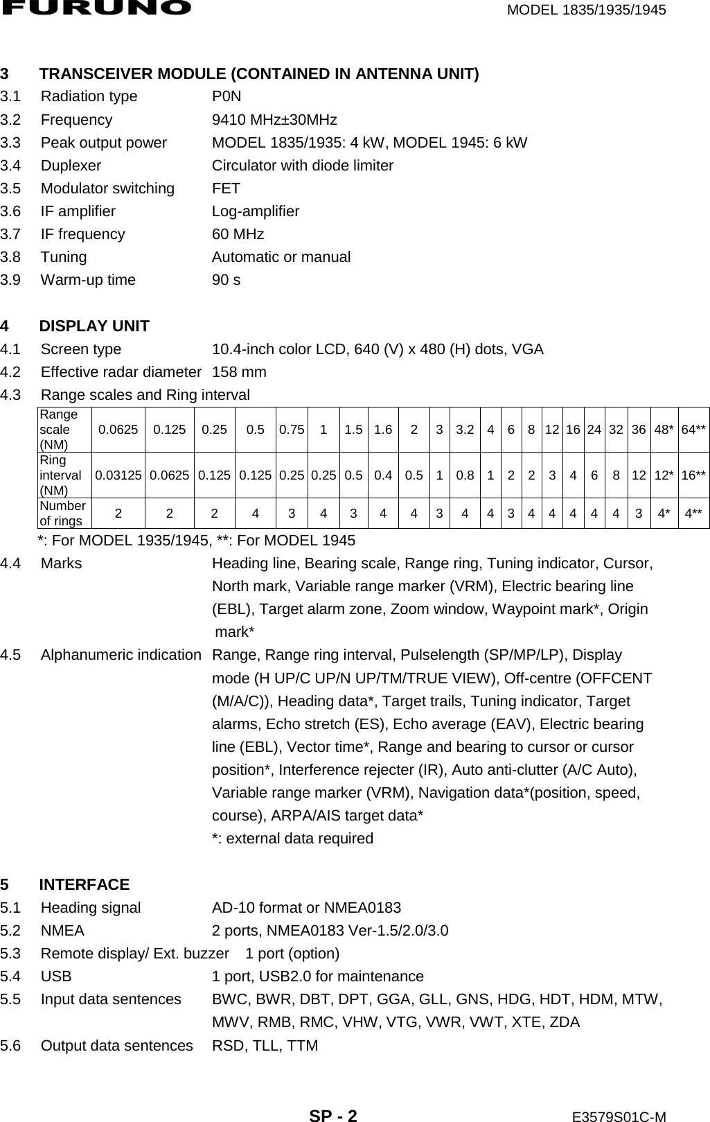
![4. AIS OPERATION4-104. Use the Cursorpad (S) to select [Yes] and press the ENTER key. All lost targets symbols are erased from the screen and the long beep sounds.5. Press the MENU key to close the menu.4.15 Symbol ColorYou can select the AIS symbol color among Green, Red (unavailable in the [IEC] or [Russian-River] purpose), Blue, White or Black.1. Press the MENU key to open the menu.2. Use the Cursorpad (S or T) to select [AIS] and press the ENTER key.3. Use the Cursorpad (S or T) to select [Color] and press the ENTER key.Color options4. Use the Cursorpad (S or T) to select the color and press the ENTER key.5. Press the MENU key to close the menu.Note: Symbols can not be shown in the same color as the background color.4.16 How to Ignore Slow TargetsYou can prevent activation of the CPA/TCPA alarm against AIS targets that are trav-eling at a speed lower than set here. The AIS symbols are not affected by this setting.1. Press the MENU key to open the menu.2. Use the Cursorpad (S or T) to select [AIS] and press the ENTER key.3. Use the Cursorpad (S or T) to select [Ignore Slow Targets] and press the ENTER key.Ignore Slow Targets setting window4. Use the Cursorpad (S or T) to select speed (0.0 - 9.9 kn) and press the ENTER key.5. Press the MENU key to close the menu.](https://usermanual.wiki/Furuno-USA/9ZWRTR059A.op-man-part-3/User-Guide-1456328-Page-1.png)
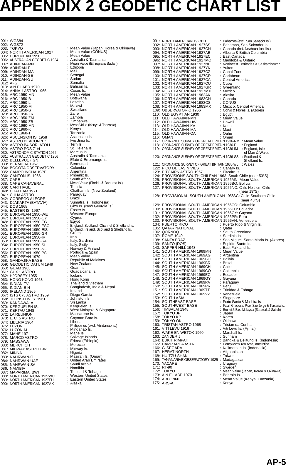
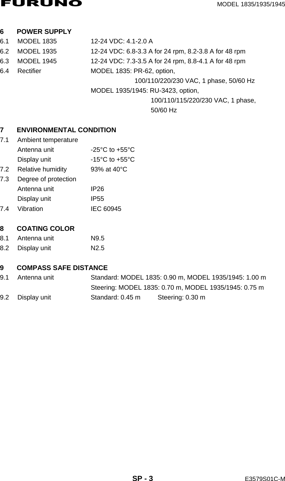
![5-15. GPS OPERATIONIf the FURUNO GPS Navigator GP-320B is connected to this radar, you can set GP-320B from this radar.5.1 Navigator Mode1. Press the MENU key to open the menu.2. Use the Cursorpad (S or T) to select [GPS] and press the ENTER key.3. Use the Cursorpad (S or T) to select [Mode] and press the ENTER key.Mode options4. Use the Cursorpad (S or T) to select [GPS] or [WAAS] then press the ENTER key.5. Press the MENU key to close the menu.5.2 DatumSelect the type of datum which matches the paper charts you use for navigation. Se-lect [WGS-84] if the radar is connected to an AIS Transponder.1. Press the MENU key to open the menu.2. Use the Cursorpad (S or T) to select [GPS] and press the ENTER key.3. Use the Cursorpad (S or T) to select [Datum] and press the ENTER key.Datum options4. Use the Cursorpad (S or T) to select the type of datum and press the ENTER key. If you select [WGS-84] or [Tokyo], go to step 7. If you select [Other], go to the next step.5. Use the Cursorpad (S or T) to select [Datum No] and press the ENTER key.Datum No setting window6. Use the Cursorpad (S or T) to select the datum number and press the ENTER key. (The setting range is 001 - 192 and 201 - 254. Refer to the appendix 2 “GEO-DETIC CHART LIST”.)7. Press the MENU key to close the menu.](https://usermanual.wiki/Furuno-USA/9ZWRTR059A.op-man-part-3/User-Guide-1456328-Page-2.png)
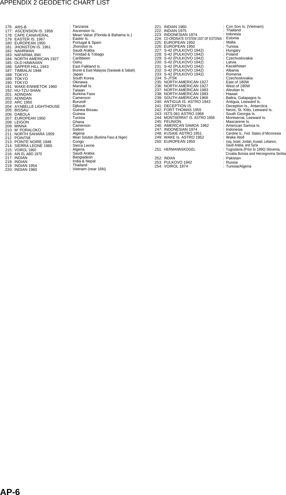
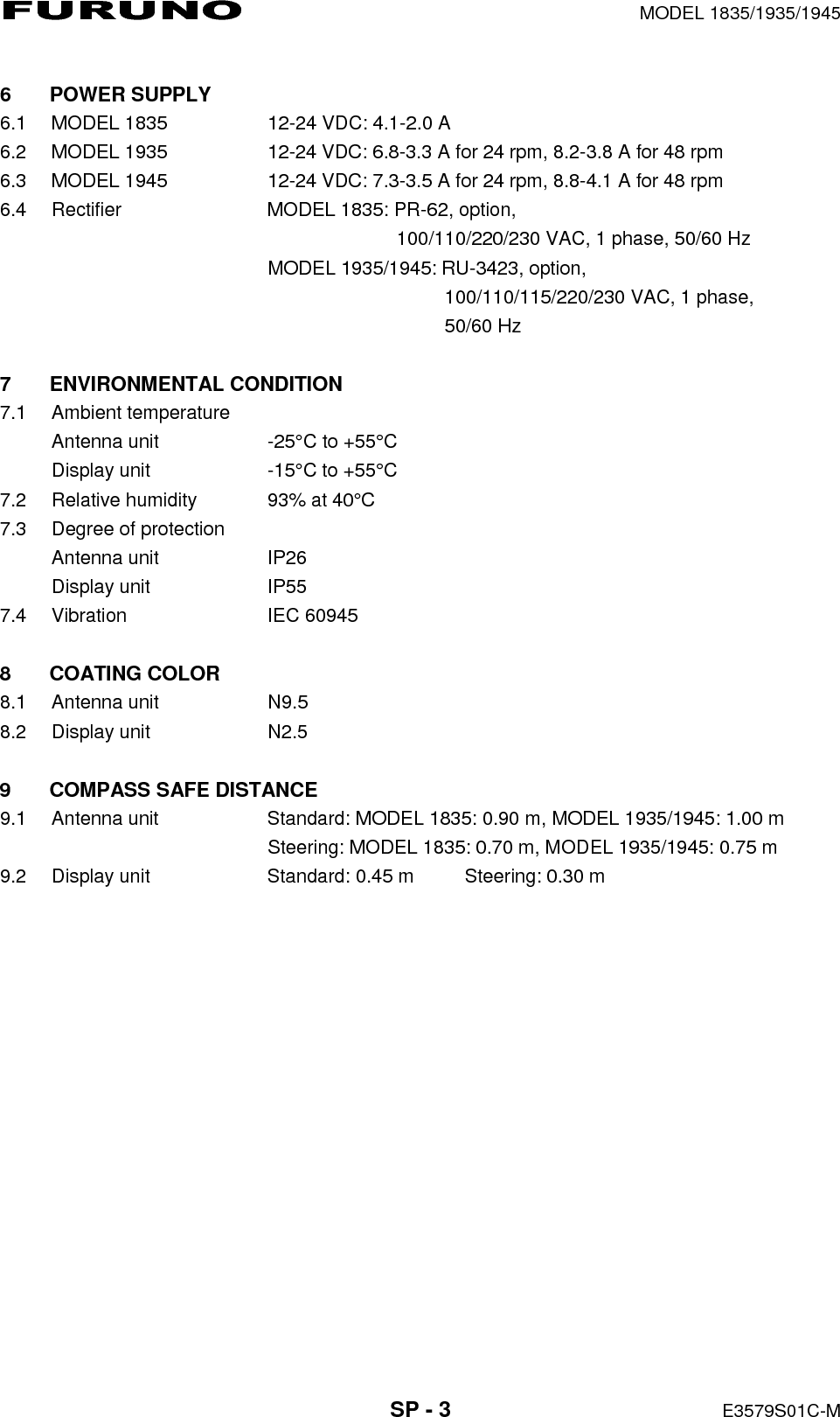
![5. GPS OPERATION5-25.3 WAAS SetupGeostationary satellites, the type used with WAAS, provide more accurate position data when compared to GPS. These satellites can be tracked automatically or manu-ally. Auto tracking automatically searches for the best geostationary satellite from your current position.1. Press the MENU key to open the menu.2. Use the Cursorpad (S or T) to select [GPS] and press the ENTER key.3. Use the Cursorpad (S or T) to select [WAAS] and press the ENTER key.WAAS options4. Use the Cursorpad (S or T) to select [Auto] or [Manual] then press the ENTER key. If you select [Auto], go to step 7. If you select [Manual], go to the next step.5. Use the Cursorpad (S or T) to select [WAAS No] and press the ENTER key.WAAS No setting window6. Use the Cursorpad (S or T) to select WAAS number and press the ENTER key. (The setting range is 120 - 158. Refer to the following table.)7. Press the MENU key to close the menu.Provider Satellite type Longitude Satellite No.WAAS Inmarsat-3-F4 (AOR-W) 142°W 122Inmarsat-3-F3 (POR) 178°E 134Intelsat Galaxy XV 133°W 135TeleSat Anik F1R 107.3°W 138EGNOS Inmarsat-3-F2 (AOR-E) 15.5°W 120Artemis 21.5°E 124Inmarsat-3-F5 (IOR-W) 25°E 126MSAS MTSAT-1R 140°E 129MTSAT-2 145°E 137](https://usermanual.wiki/Furuno-USA/9ZWRTR059A.op-man-part-3/User-Guide-1456328-Page-3.png)
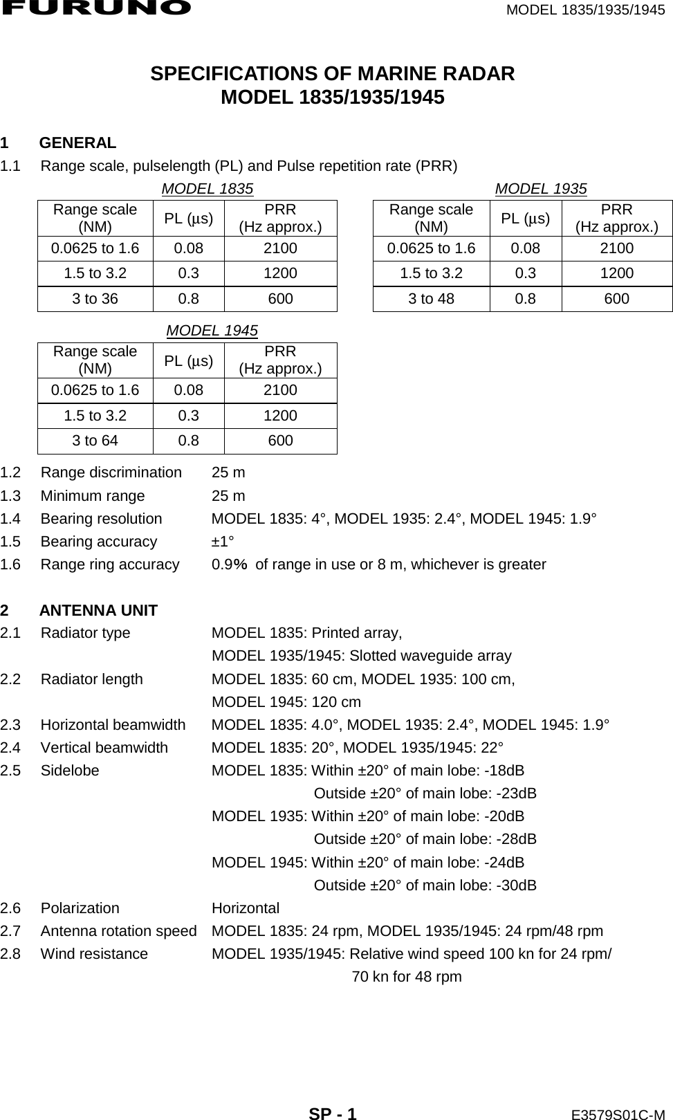
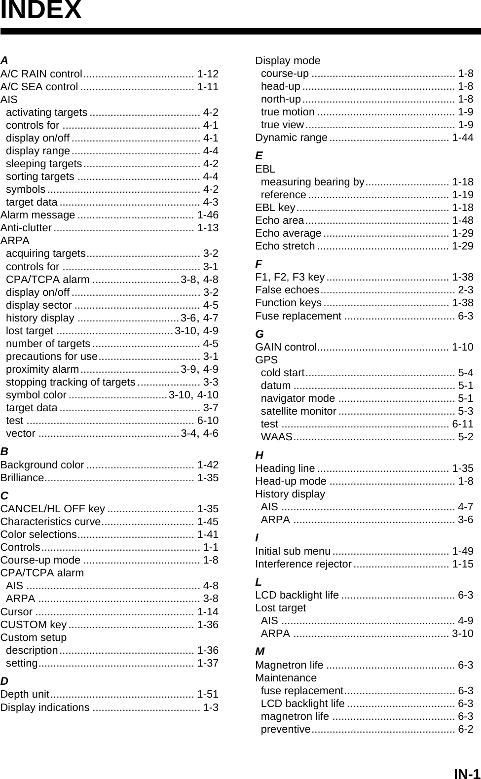
![5. GPS OPERATION5-35.4 Satellite MonitorThe Satellite Monitor provides the information about GPS and WAAS satellites. See your GPS navigator's owner's manual for detailed information.1. Press the MENU key to open the menu.2. Use the Cursorpad (S or T) to select [GPS] and press the ENTER key.3. Use the Cursorpad (S or T) to select [Satellite Monitor] and press the ENTER key.Satellite monitor4. Press the ENTER key to close only the satellite monitor display.06W3D DOP1.515m13Altitude01GPSWAAS122416SNRSatellite No.30 40 50122013118190607090813North markerDOP (Dilution of Precision, 0.0 - 99.0)SNR of tracked GPS satellitesSatellites whose SNR is above40 are used to fix position.GPS mode2D, 3D,W2D, W3DGPS satellite no.*WAAS satelliteSatellites in ring have elevationangle of 5°Satellites in ring have elevationangle of 45°Altitude ofGPS antennafrom seasurfaceSNR of trackedWAAS satelliteWN[MENU]: Close MENU [ENTER]: Close this window* Satellites used to fix position are shown in red.Satellite Monitor0109241219180713160831](https://usermanual.wiki/Furuno-USA/9ZWRTR059A.op-man-part-3/User-Guide-1456328-Page-4.png)
![5. GPS OPERATION5-45.5 Cold StartCold start, which clears the Almanac from the GPS receiver, can be necessary in the following conditions:• If you have turned off the power of the GPS receiver for a long time.• The ship has moved far away from the previous fixing position (e.g., more than 500 km).• Other reason that prevents the receiver from finding its position within five minutes after you turn on the power.To do cold start, do the following:1. Press the MENU key to open the menu.2. Use the Cursorpad (S or T) to select [GPS] and press the ENTER key.3. Use the Cursorpad (S or T) to select [Cold Start] and press the ENTER key.Cold Start options4. Use the Cursorpad (S) to select [Yes] and press the ENTER key. After processing cold start, the long beep sounds. (To stop cold start, press the CANCEL/HL OFF key instead of the ENTER key.)5. Press the MENU key to close the menu.](https://usermanual.wiki/Furuno-USA/9ZWRTR059A.op-man-part-3/User-Guide-1456328-Page-5.png)
![6. MAINTENANCE, TROUBLESHOOTING6-46.5 Simple TroubleshootingThis section provides simple troubleshooting procedures which the user can follow to restore normal operation. If you cannot restore normal operation, do not check inside the unit. Have a qualified technician check the equipment.Simple troubleshootingProblem RemedyYou cannot turn on the power. • Check for blown fuse.• Check that the power connector is fastened.• Check for corrosion on the power cable con-nector.• Check for damaged power cable.• Check battery for correct voltage output.There is no response when a key is pressed. Turn off and on the power. If you do not get a response, the key is damaged. Contact your dealer for instructions.The power is on and you operated the STBY/TX key to transmit. The marks and letters appear, but no echo ap-pears.Check that the antenna cable is fastened.Tuning is correctly adjusted, but sensitivity is poor.Replace the magnetron. Contact your dealer.The range is changed, but radar pic-ture does not change. • Try to hit the RANGE key again.• Turn off and on the display unit.Poor discrimination in range because of many echoes from the waves. Adjust A/C SEA control.The true motion presentation is not working correctly. • Check that the setting of [Display Mode] in the [Display] menu is set to [True Motion].• Check if the heading and position data are in-put and correct.The range rings are not displayed. Check that the setting of [Rings Brill] in the [Brill/Color] menu is set to other than [Off].Target is not tracked correctly be-cause of sea clutter. Adjust A/C SEA and A/C RAIN controls.](https://usermanual.wiki/Furuno-USA/9ZWRTR059A.op-man-part-3/User-Guide-1456328-Page-9.png)
![6. MAINTENANCE, TROUBLESHOOTING6-6Radar is correctly tuned but sensitivi-ty is poor.1) [2nd Echo Rejector] is [On]2) Dirt on radiator face3) Deteriorated magnetron4) Detuned MIC1) Turn off the [2nd Echo Re-jector], from the [Echo] menu.2) Clean radiator.3) Check the magnetron cur-rent with the radar transmit-ting on 48 nm range. If the current is below normal, magnetron may be defec-tive. Replace the magne-tron.4) Check MIC detecting cur-rent. If MIC detecting cur-rent is below normal value, MIC may have become de-tuned.Range changed but radar picture does not change.1) RANGE key has faults2) SPU board3) Video freeze-up1) Try to operate the RANGE key. If you can not operate the RANGE key, replace the keypad.2) Replace SPU board.3) Turn off and on radar.Range rings are not displayed. 1) Adjust their brilliance on the [Brill/Color] menu.2) SPU Board1) Replace associated circuit board if unsuccessful.2) Replace SPU Board.Problem Probable cause orcheck points Remedy](https://usermanual.wiki/Furuno-USA/9ZWRTR059A.op-man-part-3/User-Guide-1456328-Page-11.png)
![6. MAINTENANCE, TROUBLESHOOTING6-76.7 Diagnostic TestThe diagnostic test checks the system for correct operation. This test is for use by ser-vice technicians, but the user can do this test to provide the service technician with information.1. Press the MENU key to open the menu.2. Use the Cursorpad (S or T) to select [Tests] and press the ENTER key.3. Use the Cursorpad (S or T) to select [Self Test] and press the ENTER key.Self Test screenTest results• ROM, RAM: The results of the ROM and RAM test are displayed as OK or NG (No Good).• NMEA1, NMEA2: The results of the ports NMEA1 and NMEA2 are displayed as OK or "- -". Ports NMEA1 and NMEA2 require a special connector to test them. When a special connector is not connected, "- -" is shown. If "- -" is displayed with a special connector, contact your dealer for instruction.• APPLICATION VERSION, FPGA VERSION: The program numbers and pro-gram version numbers (XX) are displayed.XX: Program version no.0359246-XX.XX0359247-XX.XX10.14.248.1-403112123.4°567OKOKOKOKOKOKOKOKOKOKOKOKKey, buzzer,knob cotroland cursorpadcheck](https://usermanual.wiki/Furuno-USA/9ZWRTR059A.op-man-part-3/User-Guide-1456328-Page-12.png)
![6. MAINTENANCE, TROUBLESHOOTING6-8• HEADING PULSE, BEARING PULSE: The results of the pulse input are dis-played as OK or NG. When [Antenna Rotation] is set to [Stop], or [Watchman] is set to [Off] in the STBY mode, this test is skipped and "- -" is shown for both heading and bearing.• TUNING VOLTAGE, INDICATOR VOLTAGE, ANTENNA ROTATION, ECHO LEVEL, TRIGGER FREQUENCY: The results of measurement are displayed.• GYRO: The current gyrocompass reading is displayed.• TEMPERATURE: The result of the temperature test is displayed as OK or NG and the temperature is measured and shown.• TOTAL ON TIME, TOTAL TX TIME: The total number of hours, for which the radar has been powered and transmitted, are displayed.• INPUT NMEA window: The condition of all the NMEA sentences being input to this radar are displayed as OK or "- -". "- -" means no data input. Sentences are updated every second.Key checkPress each key one by one. A key’s on-screen location becomes green if the key is normal.Buzzer checkThe F1 key tests on/off for the panel buzzer or external buzzer. To stop the buzz-er, press the F1 key again.Knob control checkRotate each control knob. The four digits below the on-screen location for the GAIN, A/C SEA and A/C RAIN knob controls show the control position. Press each knob. The knob corresponding on-screen circle changes in green if the knob is normal.Cursorpad checkPress each arrow and diagonal dot one by one. The on-screen location changes in green if the key is normal.4. Press the MENU key three times to escape from the test.5. Press the MENU key to close the menu.](https://usermanual.wiki/Furuno-USA/9ZWRTR059A.op-man-part-3/User-Guide-1456328-Page-13.png)
![6. MAINTENANCE, TROUBLESHOOTING6-96.8 LCD Test1. Press the MENU key to open the menu.2. Use the Cursorpad (S or T) to select [Tests] and press the ENTER key.3. Use the Cursorpad (S or T) to select [LCD Pattern] and press the ENTER key.4. Press the MENU key several times to close the menu.Note 1: You can cancel the test at any time when you press the CANCEL/HL OFF key.Note 2: You can adjust the screen brilliance with the key during the test.BlackMENUkey MENUkey MENUkeyMENUkey MENUkey MENUkeyWhite RedGreen Blue Checker board design 7 tones of grayBRILL](https://usermanual.wiki/Furuno-USA/9ZWRTR059A.op-man-part-3/User-Guide-1456328-Page-14.png)
![6. MAINTENANCE, TROUBLESHOOTING6-106.9 ARPA TestIf the optional ARPA board is installed, its program number and test results (OK or NG) are shown on the screen. [ARPA Test] menu item is inoperative with no ARPA board. The radar must be transmitting to test ARPA function.1. Press the MENU key to open the menu.2. Use the Cursorpad (S or T) to select [Tests] and press the ENTER key.3. Use the Cursorpad (S or T) to select [ARPA Test] and press the ENTER key.ARPA test4. Press the MENU key three times to close the menu.XXX: Program version no.[ ARPA TEST ]ROM : OKRAM : OKARPA VERSION : 1859127XXXSPEED : OK 12.3KNCOURSE : OK 287.6°TRIGGER : OKVIDEO : OKBEARING PULSE : OKHEADING PULSE : OKMIN-HIT : 0012SCAN-TIME : 0250MANUAL-ACQ : 03AUTO-ACQ : 05FE-DATA1 : 0217FE-DATA2 : 0023ECHO NUMBER[No. 1] 0123 [No. 2] 0321 [No. 3] 0084 [No. 4] 0234[No. 5] 0110 [No. 6] 0219 [No. 7] 0073 [No. 8] 0145[MENU] x 3 : Exit](https://usermanual.wiki/Furuno-USA/9ZWRTR059A.op-man-part-3/User-Guide-1456328-Page-15.png)
![6. MAINTENANCE, TROUBLESHOOTING6-116.10 GPS TestYou can check the FURUNO GPS receiver GP-320B interfaced with this radar for cor-rect operation as follows:1. Press the MENU key to open the menu.2. Use the Cursorpad (S or T) to select [GPS] and press the ENTER key.3. Use the Cursorpad (S or T) to select [Self Test] and press the ENTER key. The program no. and result of the test are shown, as OK or NG (No Good). When NG appears, check the GPS receiver.GPS-Self Test screen4. Press any key to close the test screen.5. Press the MENU key to close the menu.48502380XXXX: Program version no. varies according to equipment connected.](https://usermanual.wiki/Furuno-USA/9ZWRTR059A.op-man-part-3/User-Guide-1456328-Page-16.png)