Furuno USA 9ZWRTR059A Marine Radar User Manual Cover
Furuno USA Inc Marine Radar Cover
UserManual.wiki
>
Furuno USA
>
9ZWRTR059A User Manual
>
op man part 2
Contents
1.
op man part 1
2.
op man part 2
3.
op man part 3
4.
inst manual
op man part 2
Navigation menu
Upload a User Manual
Namespaces
Wiki Guide
HTML
PDF
Info
Views
User Manual
Discussion / Help
Navigation
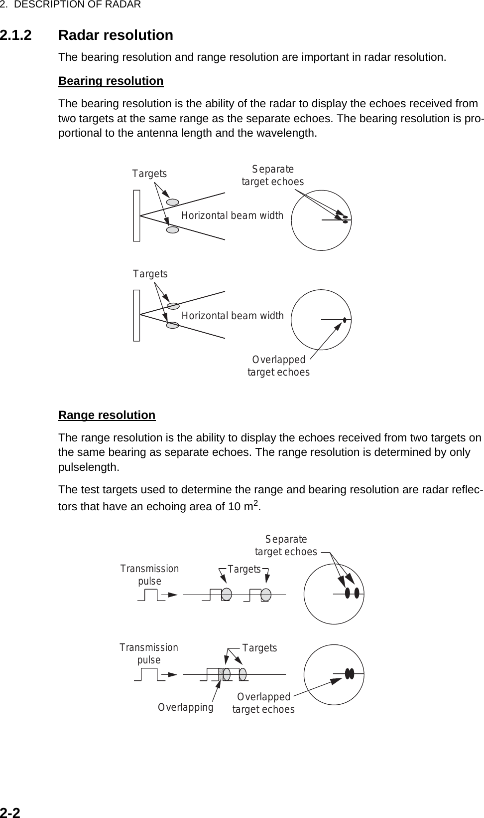
![1. DESCRIPTION OF OPERATION1-361.28 Custom Setup1.28.1 About custom setupWhen your navigating environment or task changes, you must adjust the radar. In-stead of changing radar settings case by case, you can assign the CUSTOM key to provide best settings for common conditions.There are three default custom setups for the internal computer of the radar (see the table on the next page). You can adjust these settings on the [Custom 1], [Custom 2] and [Custom 3] menus to meet your navigation needs.To activate a custom setup, press the CUSTOM key. The CUSTOM key switches be-tween Custom 1, Custom 2 or Custom 3 each time you press the key. (Custom setup numbers which are turned off are ignored.) The selected custom setup name is shown at the upper-left corner. To escape from custom setup, operate any control.1.28.2 Description of custom setup itemsDescription of custom setup itemsMenu item Available settings See section[Custom1(2 or 3)] Turn on/off each custom program.[Copy] Copy settings from the [Echo] menu. The message "Com-plete" appears after the copying is completed.[Gain Mode] [Auto]: Automatic gain adjustment according to noise level[Manual]: Manual gain adjustment 1.9[Manual Gain] Copy the current position of the GAIN knob when you do [Copy]. This item is for read-only.[Sea Mode] [Auto]: Automatic sea clutter adjustment according to sea state[Manual]: Manual sea clutter adjustment1.10[Auto Sea] [Coastal]: Suppress both land and sea clutter.[Advanced]: Automatically discriminate land echoes from sea reflections to suppress only sea reflections.1.10[Manual Sea] Copy the current position of the A/C SEA knob when you do [Copy]. This item is for read-only.[Rain Mode] [Auto]: Automatic rain clutter adjustment according to rain cloud[Manual]: Manual rain clutter adjustment1.11[Auto Rain] [Calm]: For light rain[Moderate]: When you can not reduce the rain clutter with [Calm] mode[Rough]: For heavy rain1.11[Manual Rain] Copy the current position of the A/C RAIN knob when you do [Copy]. This item is for read-only.[A/C Auto] [Off], [On] 1.12](https://usermanual.wiki/Furuno-USA/9ZWRTR059A.op-man-part-2/User-Guide-1456324-Page-1.png)
![1. DESCRIPTION OF OPERATION1-371.28.3 How to set custom setups1. Press the MENU key to open the menu.2. Use the Cursorpad (S or T) to select [Custom 1 (2 or 3)] and press the ENTER key.Custom menu3. Set menu items.Note: For easy set up, you can copy the settings of the [Echo] menu (to [Custom 1], [Custom 2], [Custom 3]). Select [Copy] and press the ENTER key. When the copying is completed, the message "Complete" appears. To erase this message, press any key.4. Press the MENU key to close the menu.[Pulse Length] [Short] or [Long], you can select on 1.5, 1.6, 3.0 and 3.2 nm ranges. 1.18[Echo Stretch] [Off], [1], [2], [3] 1.22[Echo Average] [Off], [1], [2], [Auto] 1.23[Noise Rejector] [Off], [On] 1.30[Wiper] [Off], [1], [2] 1.31[Int Rejector] [Off], [1], [2], [3] 1.14[Display-Dynamic] [Narrow]: Erase weak echoes.[Normal]: Normal use[Wide]: Display weaker echoes compared to [Narrow].1.36[Display-Curve] [1]: Reduce weak echoes.[2]: Normal use[3]: Display weaker echoes in stronger color compared to [1].1.37[Color Erase] 0 - 11 1.44.3Menu item Available settings See section](https://usermanual.wiki/Furuno-USA/9ZWRTR059A.op-man-part-2/User-Guide-1456324-Page-2.png)
![1. DESCRIPTION OF OPERATION1-381.29 How to Program Function Keys (F1, F2 and F3 keys)You can program function keys (F1, F2 and F3) to provide one-touch access to a re-quired function.Function key operationTo activate a function, press function key, F1, F2 or F3. Press same key to change the setting.The default programs are [Gain Mode] for F1, [Sea Mode] for F2, [A/C Auto] for F3. When you press the F1 or F2 key, the window for Gain/Sea/Rain indicator shows. See section 1.9 and 1.10 for operation. When you press the F3 key, [A/C Auto] is turned on.How to change a function key program1. Press the MENU key to open the menu.2. Use the Cursorpad (S or T) to select [Others] and press the ENTER key.3. Use the Cursorpad (S or T) to select [F1 (F2 or F3) Setup] and press the ENTER key.4. Use the Cursorpad (S or T) to select a function from the list and press the EN-TER key. Below are the available functions.Function list5. Press the MENU key to close the menu.Rings BrillMark BrillHL BrillCharacter BrillView PositionDisplay ColorEcho ColorBackground ColorCharacter ColorMenu TransparencyEcho Color ModeDisplay ModeZoomZoom ModeEcho AreaData BoxSTBY DisplayGain ModeSea ModeAuto SeaRain ModeAuto RainA/C AutoPulse LengthEcho StretchEcho AverageNoise RejectorWiperInt RejectorDisplay-DynamicDisplay-Curve2nd Echo RejectorTarget Alarm 1Target Alarm 2Alarm LevelWatchmanPanel BuzzerExternal BuzzerTrails-GradationTrails-ColorTrails-ModeTrails-LevelTrails-RestartTrails-NarrowTrails-Own ShipTuning ModeWPT MarkEBL ReferenceVRM UnitCursor PositionTLL Key ModeVector ReferenceHistory DotsHistory IntervalCPATCPAProximityARPA-DisplayARPA-ColorARPA-Auto AcquisitionARPA-ACK Lost TargetsAIS-DisplayAIS-ColorAIS-Sort ByAIS-ACK Lost TargetsGPS-ModeGPS-DatumGPS-WAAS](https://usermanual.wiki/Furuno-USA/9ZWRTR059A.op-man-part-2/User-Guide-1456324-Page-3.png)
![1. DESCRIPTION OF OPERATION1-391.30 Noise RejectorWhite noise can appear on the screen as random "marks". You can reduce this noise as follows:1. Press the MENU key to open the menu.2. Use the Cursorpad (S or T) to select [Echo] and press the ENTER key.3. Use the Cursorpad (S or T) to select [Noise Rejector] and press the ENTER key.Noise Rejector options4. Use the Cursorpad (S or T) to select [Off] or [On] then press the ENTER key.5. Press the MENU key to close the menu.1.31 WiperThe wiper feature automatically reduces the brilliance of unwanted weak signals (noise, sea clutter, rain clutter, etc.) and unnecessary signals, like radar interference, to clear the picture of unnecessary echoes. The result of wiper depends on the wiper setting used and whether echo averaging is turned on or off, as described below.Echo averaging and wiper states and wiper effectProcessing content A: The brilliance of unnecessary weak echoes, like noise and radar interference, is reduced to clear the picture. The difference between wiper 1 and 2 is that brilliance is lowered more slowly in 1.Processing content B: Echo averaging is automatically turned on from off when the wiper feature is turned on. You can see how the picture changes with the echo aver-aging turned off and turned on.To activate the wiper feature, do the following:1. Press the MENU key to open the menu.2. Use the Cursorpad (S or T) to select [Echo] and press the ENTER key.3. Use the Cursorpad (S or T) to select [Wiper] and press the ENTER key.Wiper options4. Use the Cursorpad (S or T) to select [1] or [2] then press the ENTER key.5. Press the MENU key to close the menu.Note: When the [Display Mode] is [True View], this function is not available (see sec-tion 1.7.2).Wiper 1 Wiper 2Echo Average Off Processing content AEcho Average On (1, 2, Auto) Processing content A Processing content B](https://usermanual.wiki/Furuno-USA/9ZWRTR059A.op-man-part-2/User-Guide-1456324-Page-4.png)
![1. DESCRIPTION OF OPERATION1-401.32 How to Reduce Second-trace EchoesEchoes from very distant targets can appear as false echoes (second-trace echoes) on the screen. The second-trace echo occurs when the return echo is received one transmission cycle later, or after a next transmission of radar pulse.Second-trace echoes1. Press the MENU key to open the menu.2. Use the Cursorpad (S or T) to select [Echo] and press the ENTER key.3. Use the Cursorpad (S or T) to select [2nd Echo Rejector] and press the ENTER key.2nd Echo Rejector options4. Use the Cursorpad (S or T) to select [Off] or [On] then press the ENTER key.5. Press the MENU key to close the menu.1.33 WatchmanThe Watchman sounds the buzzer to tell the operator to check the radar display. The radar transmits for one minute and then goes into standby for the selected time inter-val. If the target alarm is active and a target is found in the alarm zone, Watchman is cancelled, and the radar transmits continuously.How watchman operatesIn standby, the timer near the <WATCH> label at the center of the screen counts down the remaining time until the transmission. When the set time interval has passed, the audio alarm sounds, the timer disappears and the radar transmits for one minute. After one minute, the audio alarm sounds and the watch alarm timer again begins the count-down sequence.If you press the STBY/TX key before the set time interval comes, the radar goes into transmission.Second-traceechoTX repetitionActual rangeFalse echorangeST-BY5,10 or 20 min. Tx1 min.Watchmanstarts** Beep sounds just before radar transmits or goes into standby.ST-BY Tx *5,10 or 20 min.1 min.**](https://usermanual.wiki/Furuno-USA/9ZWRTR059A.op-man-part-2/User-Guide-1456324-Page-5.png)
![1. DESCRIPTION OF OPERATION1-41Do the following to activate the Watchman:1. Press the MENU key to open the menu.2. Use the Cursorpad (S or T) to select [Alarm] and press the ENTER key.3. Use the Cursorpad (S or T) to select [Watchman] and press the ENTER key.Watchman options4. Use the Cursorpad (S or T) to select [Off] or the time ([5min], [10min] or [20min]) then press the ENTER key.5. Press the MENU key to close the menu.1.34 Color Selections1.34.1 Preset colorsThis radar is preset with color combinations that provide best viewing in daytime, nighttime and twilight. Below are the default color settings for each display item and display color setting.Display item, color design and color1. Press the MENU key to open the menu.2. Use the Cursorpad (S or T) to select [Brill/Color] and press the ENTER key.3. Use the Cursorpad (S or T) to select [Display Color] and press the ENTER key.Display Color options4. Use the Cursorpad (S or T) to select the color design and press the ENTER key.5. Press the MENU key to close the menu.DIsplay item Day Night Twilight CustomCharacters Black Red Green GreenRange rings, marks Green Red Green GreenEcho Yellow Green Green YellowBackground White Black Blue Black](https://usermanual.wiki/Furuno-USA/9ZWRTR059A.op-man-part-2/User-Guide-1456324-Page-6.png)
![1. DESCRIPTION OF OPERATION1-421.34.2 Custom colorsThe custom color design lets you select preferred echo, background, characters, range rings and marks colors. Select [Custom] in the [Display Color] menu item (see section 1.34.1) to use the user selected echo, background, characters, range rings and marks colors.1. Press the MENU key to open the menu.2. Use the Cursorpad (S or T) to select [Brill/Color] and press the ENTER key.3. Use the Cursorpad (S or T) to select [Echo Color] and press the ENTER key.Echo Color options4. Use the Cursorpad (S or T) to select an echo color and press the ENTER key. [Multi] displays echoes in colors of red, yellow and green according to echo strength, and [Multi] is not available in the [IEC] or [Russian-River] mode.5. Use the Cursorpad (S or T) to select [Background Color] and press the ENTER key.Background Color options6. Use the Cursorpad (S or T) to select a background color and press the ENTER key.7. Use the Cursorpad (S or T) to select [Character Color] and press the ENTER key.Character Color options8. Use the Cursorpad (S or T) to select a character color (including range rings and marks) and press the ENTER key.9. Press the MENU key to close the menu.](https://usermanual.wiki/Furuno-USA/9ZWRTR059A.op-man-part-2/User-Guide-1456324-Page-7.png)
![1. DESCRIPTION OF OPERATION1-431.35 Navigation Data1.35.1 Navigation data during standbyThe navigation data is shown in standby when [STBY Display] on the [Display] menu is set to [Nav]. Appropriate sensors are required to display the data.Navigation data display at standby1.35.2 Navigation data at the bottom of the screen The navigation data is displayed at the bottom of the screen.Navigation dataSpeed Standby indicationDepth Water temperatureTripWind speed Wind directionTime until TXin watchmanHeading indicatorHeadingCourseTime to go todestination waypointBearing todestinationwaypoint Range to go todestination waypointWaypoint mark Your ship positionCross track error(numeric value) Cross track error(graphic): For example,when the indicator is offto the right side, steeryour ship to the left to goto the destination waypoint.- Cursor latitude position- Cursor longitude position- Time to go to cursor positionYour ship position and speed - Bearing from your ship to waypoint- Range from your ship to waypoint- Time to go from your ship position to waypointLAT 34°56.123NLON 135°34.567ESPEED 12.3KNLAT 34°56.123NLON 135°34.567ETTG 01:00BRG 14.8°RNG 0.876NMTTG 00:20OWN SHIP + CURSOR WAYPOINT](https://usermanual.wiki/Furuno-USA/9ZWRTR059A.op-man-part-2/User-Guide-1456324-Page-8.png)
![1. DESCRIPTION OF OPERATION1-44To show or hide the navigation data at the bottom of the screen, do the following:1. Press the MENU key to open the menu.2. Use the Cursorpad (S or T) to select [Display] and press the ENTER key.3. Use the Cursorpad (S or T) to select [Data Box] and press the ENTER key.Data Box options4. Use the Cursorpad (S or T) to select an option and press the ENTER key.[Off]: Turn off the data display.[Nav]: Navigation data[Target]: ARPA and AIS target data (See section 3.8 and 4.5.)[All]: Navigation data plus ARPA and AIS target data5. Press the MENU key to close the menu.1.36 Dynamic RangeYou can change the dynamic range to erase unwanted weak echoes (sea reflections, etc.). Select [Narrow], [Normal] or [Wide] depending on conditions.1. Press the MENU key to open the menu.2. Use the Cursorpad (S or T) to select [Echo] and press the ENTER key.3. Use the Cursorpad (S or T) to select [Display-Dynamic] and press the ENTER key.Display-Dynamic options4. Use the Cursorpad (S or T) to select [Narrow], [Normal] or [Wide] then press the ENTER key.[Narrow]: Erase weak echoes.[Normal]: Normal use[Wide]: Display weaker echoes compared to [Narrow].5. Press the MENU key to close the menu.](https://usermanual.wiki/Furuno-USA/9ZWRTR059A.op-man-part-2/User-Guide-1456324-Page-9.png)
![1. DESCRIPTION OF OPERATION1-451.37 Characteristics CurveYou can change the characteristics curve to reduce unwanted weak echoes (sea re-flections, etc.). Select [1], [2] or [3] depending on conditions when unwanted weak echoes hide wanted targets.1. Press the MENU key to open the menu.2. Use the Cursorpad (S or T) to select [Echo] and press the ENTER key.3. Use the Cursorpad (S or T) to select [Display-Curve] and press the ENTER key.Display-Curve options4. Use the Cursorpad (S or T) to select [1], [2] or [3] then press the ENTER key.[1]: Reduce weak echoes.[2]: Normal use[3]: Display weaker echoes in stronger color compared to [1].Display curve5. Press the MENU key to close the menu.321Input levelEcho colorstrengthStrongStrong](https://usermanual.wiki/Furuno-USA/9ZWRTR059A.op-man-part-2/User-Guide-1456324-Page-10.png)
![1. DESCRIPTION OF OPERATION1-461.38 Waypoint MarkerThe waypoint marker shows the location of the destination waypoint set on a naviga-tion plotter. The heading signal or course data are required. You can turn on/off the waypoint marker as follows:Waypoint marker1. Press the MENU key to open the menu.2. Use the Cursorpad (S or T) to select [Others] and press the ENTER key.3. Use the Cursorpad (S or T) to select [WPT Mark] and press the ENTER key.WPT Mark options4. Use the Cursorpad (S or T) to select [Off] or [On] then press the ENTER key.5. Press the MENU key to close the menu.1.39 Alarm MessageThe alarm status window shows all currently violated alarms.Note: The alarm status window is not automatically displayed when an alarm occurs.1. Press the MENU key to open the menu.2. Use the Cursorpad (S or T) to select [Alarm] and press the ENTER key.+Waypointmarker](https://usermanual.wiki/Furuno-USA/9ZWRTR059A.op-man-part-2/User-Guide-1456324-Page-11.png)
![1. DESCRIPTION OF OPERATION1-473. Use the Cursorpad (S or T) to select [Alarm Status] and press the ENTER key.Alarm Status display4. Press the CANCEL/HL OFF key to close the alarm status display.5. Press the MENU key to close the menu.Alarm category MeaningSIGNAL MISSING*TRIGGER Trigger signal lost (only for remote display)HEADING Heading signal lostBEARING Bearing signal lostGYRO AD-10 format gyro signal lostVIDEO Video signal lostPOSITION NMEA format position data lostNMEA_HDG NMEA format heading signal lostTARGET ALARM1(2)IN An echo has entered a target alarm zone.OUT An echo has exited a target alarm zone.ARPA ALARMCOLLISION CPA and TCPA of an ARPA target is less than CPA and TCPA alarm settings.LOST Acquired ARPA target becomes lost.PROXIMITY The range to an ARPA target is less than the user-set proximity alarm range.AIS ALARMCOLLISION CPA and TCPA of an AIS target is less than CPA and TCPA alarm settings.PROXIMITY The range to an AIS target is less than the user-set prox-imity alarm range.TRIGGER HEADING BEARING GYROVIDEO POSITION NMEA_HDGIN OUTIN OUTCOLLISION LOST PROXIMITYCOLLISION PROXIMITYTX ANT CH1 CH2 CH70 FAIL MKDEPFS L/L SOG COG HDG ROTOVER_TEMP](https://usermanual.wiki/Furuno-USA/9ZWRTR059A.op-man-part-2/User-Guide-1456324-Page-12.png)
![1. DESCRIPTION OF OPERATION1-48*: Have a qualified technician check the equipment.1.40 Echo AreaYou can select the display area from [Normal] or [Full Screen].Echo area1. Press the MENU key to open the menu.2. Use the Cursorpad (S or T) to select [Display] and press the ENTER key.AIS SYSTEM*TX TX stopped or TX errorANT Antenna VSWR problemCH1 TDM2 RX1 board problemCH2 TDM2 RX2 board problemCH70 RX channel 70 problemFAIL System failureMKD Minimum input device lostEPFS Navigator (GPS, etc.) problemL/L Position data lostSOG Speed data lostCOG Course data lostHDG Heading data lostROT Rate of turn data lostOTHER*OVER_TEMP The temperature of the equipment is more than the spec-ified value.Alarm category MeaningNormal Full ScreenArea in which echoes are displayed](https://usermanual.wiki/Furuno-USA/9ZWRTR059A.op-man-part-2/User-Guide-1456324-Page-13.png)
![1. DESCRIPTION OF OPERATION1-493. Use the Cursorpad (S or T) to select [Echo Area] and press the ENTER key.Echo Area options4. Use the Cursorpad (S or T) to select [Normal] or [Full Screen] then press the EN-TER key.5. Press the MENU key to close the menu.1.41 Initial Sub MenuThe [Initial] sub menu in the [System] menu contains the items which allow you to cus-tomize your radar to meet your needs.1.41.1 How to open the Initial sub menu1. Press the MENU key to open the menu.2. Use the Cursorpad (S or T) to select [Initial] and press the ENTER key.Initial sub menu1.41.2 Description of Initial sub menu[Key Beep]: When a key is pressed, a beep sounds. You can turn on or off this beep.[Offcenter Speed]: Set the speed of your ship to calculate amount of your ship’s off-center. The setting range is 1-99 (kn).[Compass Type]: Select the type of bearing sensor connected to the radar; [True] (gyrocompass, satellite compass) or [Magnetic] (magnetic compass).[Range Preset]: You can select the radar ranges. Select a range and press the EN-TER key to switch on and off. At least two ranges must be turned on. The maximum range available depends on the radar model. 0.0625 is not available in KM (kilome-ters).](https://usermanual.wiki/Furuno-USA/9ZWRTR059A.op-man-part-2/User-Guide-1456324-Page-14.png)
![1. DESCRIPTION OF OPERATION1-51[Wind Direction]: Wind direction is shown as [Apparent] or [True].[NMEA Port 1]: Set the baud rate of the equipment connected to Port 1 ([Auto], [4800], or [38400] (bps)). [Auto] provides automatic detection of baud rate from 4800, 9600, 19200 or 38400 (bps).[NMEA Port 2]: Same function as Port 1 but for Port 2.[NMEA Mixing Out]: Data input to Port 1 may be output from Port 2 mixed with data output to Port 2. Select [On] to use this feature.1.42 Units Sub MenuYou can select the unit of measurement for range, ship speed, depth, temperature and wind speed on the [Units] sub menu in the [System] menu. You can not open this sub menu in normal operation. To open this menu, select [Units], hold the CANCEL/HL OFF key and press the MENU key five times.Units sub menu[Range Unit]: NM, KM, SM[Ship Speed Unit]: kn, km/h, mph[Depth Unit]: m, ft, fa, pb, HR[Temperature Unit]: °C, °F[Wind Speed Unit]: kn, km/h, mph, m/s](https://usermanual.wiki/Furuno-USA/9ZWRTR059A.op-man-part-2/User-Guide-1456324-Page-16.png)
![1. DESCRIPTION OF OPERATION1-521.43 Sector BlankYou must prevent the transmission in some areas to protect passengers and crew from microwave radiation. Also, if the reflections of echoes from the mast appear on the screen, you must prevent the transmission in that area. You can set two sectors.1. Press the MENU key to open the menu.2. Use the Cursorpad (S or T) to select [Sector Blanks] and press the ENTER key.3. Use the Cursorpad (S or T) to select [Sect-Blank 1 (or 2) Status] and press the ENTER key.Sect-Blank Status options4. Use the Cursorpad (S or T) to select [On] and press the ENTER key.5. Use the Cursorpad (S or T) to select [Sect-Blank 1 (or 2) Start] and press the ENTER key.Sect-Blank Start setting window6. Use the Cursorpad (S or T) to set the start point of the sector and press the EN-TER key.7. Use the Cursorpad (S or T) to select [Sect-Blank 1 (or 2) End] and press the EN-TER key.Sect-Blank End setting window8. Use the Cursorpad (S or T) to set the end point of the sector and press the EN-TER key.Note 1: You can not set the sector more than 180 degrees.Note 2: You can not set the total width of sector 1 and sector 2 more than 270 degrees.9. Press the MENU key to close the menu.As shown in the following illustration, dashed lines mark the start and end points of the sector.](https://usermanual.wiki/Furuno-USA/9ZWRTR059A.op-man-part-2/User-Guide-1456324-Page-17.png)
![1. DESCRIPTION OF OPERATION1-53Sector blank1.44 Other Menu ItemsThis section describes the menu items not previously described.1.44.1 Menu items on the [Brill/Color] menu[View Position]: You can select the angle from where you see the screen.View Position options[Menu Transparency]: You can select the degree of transparency of the menu win-dow so the menu window does not hide the echo display. [4] is the greatest degree of transparency. [Off] functions to hide the echo display behind the menu window com-pletely.Note: Alpha blending technology is used for transparency effects.Menu Transparency options[Echo Color Mode]: You can select the color palette from [System] or [Custom]. [Sys-tem] is the pre-set color palette and [Custom] is the color palette you can set yourself. This function is not available in the [IEC] or [Russian-River] mode.+Area of notransmissionStart bearingof sectorEnd bearingof sector](https://usermanual.wiki/Furuno-USA/9ZWRTR059A.op-man-part-2/User-Guide-1456324-Page-18.png)
![1. DESCRIPTION OF OPERATION1-54[Custom Echo Color]: You can customize the echo color with the following two meth-ods. This function is not available in the [IEC] or [Russian-River] mode.Custom Echo Color setting windowMethod 1: 1) Select the echo rank to change on the [Rank] (setting range: 1 - 31).2) Set the RGB values for selected echo rank on the [Red], [Green] and [Blue] (setting range: 0 - 63).Method 2: 1) Select 31 on the [Rank].2) Set the RGB values for 31 echo rank on the [Red], [Green] and [Blue] (setting range: 0 - 63).3) Interpolate the RGB values between the maximum rank and minimum rank on the [Fitting To Curve] with the following curves (setting range: -20 to 20). Setting range > 0: Logarithmic curve, useful to emphasize the weak echoes. Setting range = 0: Straight line Setting range < 0: Exponential curve, useful to emphasize the strong echoes.[Copy To Custom]: Copy the color palette from [System] to [Custom].](https://usermanual.wiki/Furuno-USA/9ZWRTR059A.op-man-part-2/User-Guide-1456324-Page-19.png)
![1. DESCRIPTION OF OPERATION1-551.44.2 Menu items on the [Display] menu[Base Text Display]: You can select on/off for the text indications of the following items on the display. The settings on this function are used when you set [Echo Area] to [Full Screen] on the [Display] menu. This function is not available in the [IEC] or [Russian-River] mode.Base Text Display optionsThe text indications set to off appear when you operate any key. The indications dis-appear when there is no key operation for 10 seconds.[Gain/Sea/Rain Bar]: Open the Gain/Sea/Rain indicator. You can check the current settings.Gain/Sea/Rain Bar[STBY Display]: Set the function of the standby display.STBY Display options [Normal]: Display "ST-BY" at the screen center. [Nav]: Display navigation data. [Economy]: Turn off the backlight of the LCD. The radar must be switched from TX to ST-BY to activate this mode.Press the ENTER keyto change betweenon and off.](https://usermanual.wiki/Furuno-USA/9ZWRTR059A.op-man-part-2/User-Guide-1456324-Page-20.png)
![1. DESCRIPTION OF OPERATION1-561.44.3 Menu items on the [Echo] menu[Color Erase]: Erase the lower echo color whose level is set here. Set a large value to display only the stronger echoes.Color Erase setting window1.45 Remote DisplayYou can use this radar as a remote display when you set [Input Source] to [Slave] on the [Installation] sub menu. When this setting is done, the menu and display change as described below. To display the radar image on the remote display, transmit from the main radar.Note: The message "Please turn to STBY-mode when you change this setting." ap-pears when you switch the mode in transmission.Unavailable menu itemsThe menu items are not available with the remote display as shown in the table.Display appearanceThe display changes as shown in the following illustration.Transmitting or standby display indications for remote displayMenu Unavailable menu item(s)[Echo] [Pulse Length], [2nd Echo Rejector][Custom 1, 2, 3] [Pulse Length][Alarm] [Watchman][Tuning] All menu items are inoperative.[System] - [Sector Blanks] All menu items are inoperative.[System] - [Installation] [Antenna Rotation], [MBS Adjust],[Auto Install Setup], [Total TX Time]HDGOFFCENT(M) Shown when displayunit functions asremote display.Tuning indicatoris not displayed.Pulselength is not displayed.WTC is not displayed.SLAVE0.5NM0.125CS1H UPTRAIL(T)06MINALM1_ACKALM2_OUT359.9°](https://usermanual.wiki/Furuno-USA/9ZWRTR059A.op-man-part-2/User-Guide-1456324-Page-21.png)
![1. DESCRIPTION OF OPERATION1-57Items unavailable with Function key F1, F2 and F3• [Pulse Length] ([Echo] menu)• [2nd Echo Rejector] ([Echo] menu)• [Watchman] ([Alarm] menu)• [Tuning Mode] ([Tuning] menu)Total TX time indicationThe total TX time (TX TIME XXXXXX.XH) does not appear on the diagnostic test or on the Normal standby display.](https://usermanual.wiki/Furuno-USA/9ZWRTR059A.op-man-part-2/User-Guide-1456324-Page-22.png)


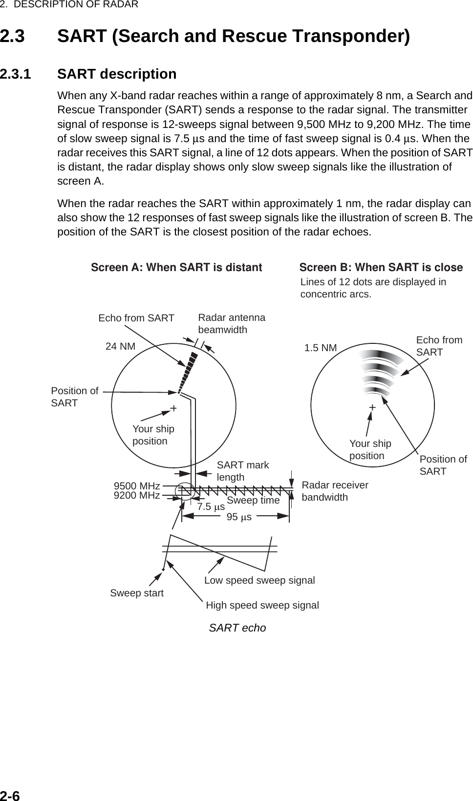
![2. DESCRIPTION OF RADAR2-72.3.2 General remarks on receiving SARTSART range errorsWhen the SART is at a range greater than approximately 1 nm, the first dot is dis-played at 0.64 nm beyond the true position of the SART. When the range closes so that the fast sweep responses are seen also, the first range echoes are displayed at 150 m beyond the true position.Range scaleWhen you find the SART position, do as follows:1. Use the RANGE key to set the range scale to 6 nm or 12 nm.2. Turn off [A/C Auto].3. Turn off [Int Rejector].SART displayTo display only the SART echo clearly on the radar screen, reduce the tuning on man-ual mode. The normal radar echoes get weak, however, the SART echoes remain. Your ship comes close to the SART, the arc for the SART display becomes larger. Most of the radar screen becomes fuzzy. Adjust the A/C SEA and GAIN controls to display the necessary screen.](https://usermanual.wiki/Furuno-USA/9ZWRTR059A.op-man-part-2/User-Guide-1456324-Page-30.png)
![3-13. ARPA OPERATIONThe Automatic Radar Plotter ARP-11 (option) manually or automatically acquires and tracks ten targets. Once a target is acquired automatically or manually, a target is au-tomatically tracked within 0.1 to 16 nm.3.1 Precautions for Use3.2 Controls for Use with ARPAENTER: Acquire cursor-selected target. Display data for tracked target (in the data box at the bottom of the screen).CANCEL/HL OFF: Remove data of cursor-selected tracked target from the data box. Stop tracking the cursor-selected target (when its data is not displayed in the data box).MENU: Access the [Target] and [ARPA] menus for ARPA operations.Cursorpad: Select a target to acquire (or cancel the tracking). Select a target to show (or remove) target data.Do not depend on one navigation devicefor the navigation of the ship. Thenavigator must check all aids availableto confirm position. Electronic aids arenot a replacement for basic navigationprinciples and common sense.· The ARPA automatically tracks an automatically or manually acquired radar target and calculates its course and speed, indicating them by a vector. Since the data from the auto plotter depend on the selected radar targets, the radar must be optimally tuned for use with the auto plotter, to ensure required targets will not be lost or unnecessary targets like sea returns and noise will not be acquired and tracked.· A target is not always a landmass, reef, ship, but can be returns from the sea surface and clutter. As the level of clutter changes with the environment, the operator must correctly adjust the A/C SEA, A/C RAIN and GAIN controls so that the target echoes do not disappear from the radar screen.The plotting accuracy and response ofthis ARPA meets IMO standards.The tracking accuracy is affected by thefollowing:· The tracking accuracy is affected by course change. One to two minutes is required to restore vectors to full accuracy after a sudden course change. (The actual amount depends on gyrocompass specifications.)· The amount of tracking delay is inversely proportional to the relative speed of the target. Delay is on the order of 15-30 seconds for high relative speed; 30-60 seconds for low relative speed.The display accuracy is affected by thefollowing:· Echo intensity· Pulse width of radar transmission· Radar bearing error· Gyrocompass error· Course change (your ship or target)CAUTIONCAUTIONCAUTIONCAUTION](https://usermanual.wiki/Furuno-USA/9ZWRTR059A.op-man-part-2/User-Guide-1456324-Page-32.png)
![3. ARPA OPERATION3-23.3 ARPA Display On/OffYou can turn the ARPA display on or off. The system continuously tracks ARPA tar-gets regardless of this setting.1. Press the MENU key to open the menu.2. Use the Cursorpad (S or T) to select [ARPA] and press the ENTER key.3. Use the Cursorpad (S or T) to select [Display] and press the ENTER key.ARPA-Display options4. Use the Cursorpad (S or T) to select [Off] or [On] then press the ENTER key.5. Press the MENU key to close the menu.3.4 How to Acquire and Track the TargetsTen targets are acquired and tracked manually or automatically.3.4.1 Manual acquisitionYou can acquire up to ten ARPA targets. When the automatic acquisition ([Auto Ac-quisition] on the [ARPA] menu) is set to on, you can manually acquire up to five tar-gets.1. Use the Cursorpad to put the cursor on the target to acquire.2. Press the ENTER key.The ARPA target symbol changes over time as below. A vector which indicates the motion direction of the target appears approximately one minute after acquisition.ARPA target symbolTarget numberRiver and Sea (Non-IEC system): An acquired target gets the youngest unused number. When a target is lost and disappears from the number list, the next acquired target takes the number of that lost target (ie; In a 5 target list, if the target 2 is lost, the next acquired target takes the number of target 2).IEC and Russian-River (IEC system): An acquired target gets the youngest unused number. When a target is lost and disappears from the number list, the next acquired target takes the next sequential number until reaching a maximum 10. If the target number reaches a maximum 10, the next acquired target takes the number of a pre-viously lost target.At acquisition 1 min. afteracquisition3 min. afteracquisition01 Target numberVector0101](https://usermanual.wiki/Furuno-USA/9ZWRTR059A.op-man-part-2/User-Guide-1456324-Page-33.png)
![3. ARPA OPERATION3-33.4.2 Automatic acquisitionWhen you set an automatic acquisition area, the ARPA can acquire up to five targets automatically.The automatic acquisition area is 2.0 to 2.5 nm in range and ±45° on either side of the heading line in bearing. When you change the automatic acquisition to manual acqui-sition, targets being tracked in automatic acquisition are continuously tracked.Automatic acquisition area1. Press the MENU key to open the menu.2. Use the Cursorpad (S or T) to select [ARPA] and press the ENTER key.3. Use the Cursorpad (S or T) to select [Auto Acquisition] and press the ENTER key.Auto Acquisition options4. Use the Cursorpad (S or T) to select [On] and press the ENTER key.5. Press the MENU key to close the menu.3.5 How to Stop the Tracking of ARPA TargetWhen ten targets have been acquired, no more acquisition occurs unless targets are cancelled. If you acquire additional targets, you must cancel one or more individual targets, or all targets. Use one of the following procedures.3.5.1 How to stop the tracking of selected targets1. Use the Cursorpad to put the cursor on the target to cancel the tracking.2. Press the CANCEL/HL OFF key to cancel the tracking and erase the ARPA sym-bol. The unit beeps twice and the symbol is erased from the screen.3.5.2 How to stop the tracking of all targets1. Press the MENU key to open the menu.2. Use the Cursorpad (S or T) to select [ARPA] and press the ENTER key.Automatic acquisition area45° port 45° starboard2.0 - 2.5 nm Heading line](https://usermanual.wiki/Furuno-USA/9ZWRTR059A.op-man-part-2/User-Guide-1456324-Page-34.png)
![3. ARPA OPERATION3-43. Use the Cursorpad (S or T) to select [All Cancel] and press the ENTER key.All Cancel options4. Use the Cursorpad (S) to select [Yes] and press the ENTER key. All symbols are erased from the screen and the long beep sounds.5. Press the MENU key to close the menu.3.6 Vector Attributes3.6.1 What is a vector?A vector is a line extending from a tracked target. A vector shows speed and course of the target. The top of a vector shows estimated position of the target after the se-lected vector time elapses. If you extend the vector length (time), you can evaluate the risk of collision with any target.When vector time is 15 minutes3.6.2 Vector time and vector reference1. Press the MENU key to open the menu.2. Use the Cursorpad (S or T) to select [Target] and press the ENTER key.Target menuVectorCurrent position of the targetVector timeVector timeVector time Predicted position of the target in 15 minutes later](https://usermanual.wiki/Furuno-USA/9ZWRTR059A.op-man-part-2/User-Guide-1456324-Page-35.png)
![3. ARPA OPERATION3-53. Use the Cursorpad (S or T) to select [Vector Time] and press the ENTER key.Vector Time setting window4. Use the Cursorpad (S or T) to select time and press the ENTER key.5. Use the Cursorpad (S or T) to select [Vector Reference] and press the ENTER key.Vector Reference options6. Use the Cursorpad (S or T) to select [Relative] or [True] then press the ENTER key. This function is not activate for [IEC] or [Russian-River] purpose. The mode is set to [True].[Relative]: Other ships’ vectors are displayed relative to your ship. This mode helps find targets on a collision course. If a ship is on a collision course with your ship, the vector of a ship points toward your ship position.[True]: Your ship’s and other ships’ vectors are displayed at their true motions. This mode helps discriminate between moving and stationary targets.7. Press the MENU key to close the menu.Note: The functions of the [Target] menu are shared by ARPA and AIS.3.6.3 Vector of your shipThe vector of your ship is shown as an arrow from your ship position. The vector of your ship is shown on the following conditions:• Connect ARP-11 (option)• Select [True] on the menu item [Vector Reference] on the [Target] menu• Independent of on/off on the menu item [Display] on the [ARPA] menuNote: The vector of your ship is shown in the same color as the ARPA symbol color (see section 3.12).](https://usermanual.wiki/Furuno-USA/9ZWRTR059A.op-man-part-2/User-Guide-1456324-Page-36.png)
![3. ARPA OPERATION3-63.7 History Display (target past position)This radar can display time-spaced dots (maximum ten dots) that mark the past posi-tions of any tracked ARPA target. You can evaluate actions of a target by the spacing between dots. Below are examples of dot spacing and target movement.Target movement and history displayYou can select the number of history dots to display and the time interval to display the history dots.1. Press the MENU key to open the menu.2. Use the Cursorpad (S or T) to select [Target] and press the ENTER key.3. Use the Cursorpad (S or T) to select [History Dots] and press the ENTER key.History Dots options4. Use the Cursorpad (S or T) to select number of history dots to display (5 or 10) or select [Off] to turn off the history display.5. Press the ENTER key.+Vector ofyour ship01Data box02Cursor0304(a) Ship turning (b) Ship running straight (c) Ship reduced speed (d) Ship increased speed](https://usermanual.wiki/Furuno-USA/9ZWRTR059A.op-man-part-2/User-Guide-1456324-Page-37.png)
![3. ARPA OPERATION3-76. Use the Cursorpad (S or T) to select [History Interval] and press the ENTER key.History Interval options7. Use the Cursorpad (S or T) to select the time interval and press the ENTER key.8. Press the MENU key to close the menu.3.8 ARPA Target DataYou can show the data for a tracked ARPA target in the data box at the bottom of the screen. To display ARPA target data, the menu item [Display] on the [ARPA] menu must be set for [On] and the menu item [Data Box] on the [Display] menu must be set for [Target] or [All].1. Use the Cursorpad to put the cursor on an ARPA target.2. Press the ENTER key to show the data of the target.ARPA target dataThe symbol for the selected ARPA target is enlarged double to distinguish from other symbols.To remove the data of a target from a data box, put the cursor on its target symbol and press the CANCEL/HL OFF key.TRUE 05:00 <ARPA> No. 01BRG 53.7°T RNG 2.987NM CRS 350.4° SOG 23.45KNCPA 1.65NM TCPA 06:14Vector referenceVector time Target no.Bearing, range, course, speed CPA, TCPA+ARPA targetselected fordata display01ARPA targetData box02Cursor](https://usermanual.wiki/Furuno-USA/9ZWRTR059A.op-man-part-2/User-Guide-1456324-Page-38.png)
![3. ARPA OPERATION3-83.9 CPA/TCPA AlarmSet CPA (Closest Point of Approach) alarm range and TCPA (predicted Time to CPA) alarm time to alert you to targets that can be on a collision course. When CPA and TCPA of any ARPA target become less than the preset CPA and TCPA alarm settings, the audio alarm sounds. The alarm message "COLLISION" appears. The target sym-bol changes to a dangerous target symbol (triangle) and flashes with its vector. You can stop the audio alarm with any key. The flashing of the triangle stops when the tracked ARPA target is not in the CPA and TCPA alarm setting. The ARPA continu-ously monitors CPA and TCPA of all tracked ARPA targets.Dangerous target symbolThis feature helps identify targets that can be on a collision course. Correctly adjust GAIN, A/C SEA, A/C RAIN and other radar controls.1. Press the MENU key to open the menu.2. Use the Cursorpad (S or T) to select [Target] and press the ENTER key.3. Use the Cursorpad (S or T) to select [CPA] and press the ENTER key.CPA options4. Use the Cursorpad (S or T) to select CPA distance and press the ENTER key.CAUTIONCAUTIONDo not depend on the CPA/TCPA alarmas the only method to detect the risk ofcollision. The navigator is not releasedof the responsibility to keep visual cautionfor collision situations, whether or not theradar or other plotting aid is in use.](https://usermanual.wiki/Furuno-USA/9ZWRTR059A.op-man-part-2/User-Guide-1456324-Page-39.png)
![3. ARPA OPERATION3-95. Use the Cursorpad (S or T) to select [TCPA] and press the ENTER key.TCPA options6. Use the Cursorpad (S or T) to select TCPA and press the ENTER key.7. Press the MENU key to close the menu.3.10 Proximity AlarmThe proximity alarm alerts you when an ARPA target is within the range you set. The audio alarm sounds and the alarm message "PROXIMITY" appears. The target sym-bol changes to a dangerous target symbol (triangle, see section 3.9) and flashes with its vector. Press any key to stop the audio alarm. The flashing continues until the tar-get is not within the range set, the alarm range is changed to exclude the target, or the proximity alarm is deactivated.1. Press the MENU key to open the menu.2. Use the Cursorpad (S or T) to select [Target] and press the ENTER key.3. Use the Cursorpad (S or T) to select [Proximity] and press the ENTER key.Proximity options4. Use the Cursorpad (S or T) to select the range and press the ENTER key.5. Press the MENU key to close the menu.](https://usermanual.wiki/Furuno-USA/9ZWRTR059A.op-man-part-2/User-Guide-1456324-Page-40.png)
![3. ARPA OPERATION3-103.11 Lost TargetWhen the system detects a lost target, the audio alarm sounds and the alarm mes-sage "LOST" appears. The target symbol becomes a flashing square like the following illustration. When the system detects the target again, the target symbol becomes a normal symbol.Lost target symbolTo erase a lost target symbol, put the cursor on the symbol and press the CANCEL/HL OFF key. If you leave a lost target symbol flashing, the symbol disappears after one minute.You can remove all lost ARPA targets from the screen as follows:1. Press the MENU key to open the menu.2. Use the Cursorpad (S or T) to select [ARPA] and press the ENTER key.3. Use the Cursorpad (S or T) to select [ACK Lost Targets] and press the ENTER key.ACK Lost Targets options4. Use the Cursorpad (S) to select [Yes] and press the ENTER key. All lost targets symbols are erased from the screen and the long beep sounds.5. Press the MENU key to close the menu.3.12 Symbol ColorYou can select the ARPA symbol color from Green, Red, Blue, White or Black.1. Press the MENU key to open the menu.2. Use the Cursorpad (S or T) to select [ARPA] and press the ENTER key.3. Use the Cursorpad (S or T) to select [Color] and press the ENTER key.Color options4. Use the Cursorpad (S or T) to select the color and press the ENTER key.5. Press the MENU key to close the menu.Note: Symbols can not be shown in the same color as the background color.](https://usermanual.wiki/Furuno-USA/9ZWRTR059A.op-man-part-2/User-Guide-1456324-Page-41.png)
![4-14. AIS OPERATIONConnected to the FURUNO AIS Transponders FA-150, FA-100, FA-50 or the AIS Re-ceiver FA-30, the MODEL 1835 series can show the name, position and other naviga-tion data of the nearest 100 AIS transponder-equipped ships.This radar accepts position data fixed by WGS-84 geodetic datum. Set the datum to WGS-84 on the GPS navigator connected to this radar. If this radar is interfaced with the FURUNO GPS Navigator GP-320B, see section 5.2 for the procedure.4.1 Controls for Use with AISENTER: Activate cursor-selected target. Display data for selected active target (in the data box at the bottom of the screen).CANCEL/HL OFF: Remove data of cursor-selected AIS target from the data box. Sleep cursor-selected target (when its data is not displayed in the data box).MENU: Access the [Target] and [AIS] menus for AIS operations.Cursorpad: Select a target to activate (or sleep). Select a target to show (or remove) target data.4.2 AIS Display On/OffYou can turn the AIS display on or off. The system continues processing AIS targets regardless of on/off for AIS display when the AIS transponder is turned on.1. Press the MENU key to open the menu.2. Use the Cursorpad (S or T) to select [AIS] and press the ENTER key.AIS menu](https://usermanual.wiki/Furuno-USA/9ZWRTR059A.op-man-part-2/User-Guide-1456324-Page-42.png)
![4. AIS OPERATION4-23. Use the Cursorpad (S or T) to select [Display] and press the ENTER key.AIS-Display options4. Use the Cursorpad (S or T) to select [Off] or [On] then press the ENTER key.5. Press the MENU key to close the menu.4.3 AIS SymbolsWhen the AIS is turned on, AIS targets are displayed with AIS symbol as below.AIS symbolsNote: The AIS symbols are momentarily erased after the screen is redrawn when the heading is changed on the head-up mode.4.4 Activating, Sleeping TargetsWhen you change a sleeping target to an activated target, a vector shows the course and speed of that target. You can easily judge the target movement by the vector.Activated targetSleepingtarget ActivatedtargetDangerous targetLost target Target selectedfor data displayHeading lineSOG (Speed Over Ground) andCOG (Course over Ground) vector(If there is no heading data,the line points in direction of COG.)ROT(Rate of Turn)](https://usermanual.wiki/Furuno-USA/9ZWRTR059A.op-man-part-2/User-Guide-1456324-Page-43.png)
![4. AIS OPERATION4-3When there are many activated targets on the screen, you can not easily distinguish the activated targets from the radar images or ARPA targets. You can sleep an acti-vated target for easy view of radar images.Sleeping targetTo activate a target: Put the cursor on the target and press the ENTER key. To sleep a target: Put the cursor on the target and press the CANCEL HL/OFF key.4.5 AIS Target DataYou can show the AIS target data in the data box at the bottom of the screen. To dis-play AIS target data, the menu item [Display] on the [AIS] menu must be set for [On] and the menu item [Data Box] on the [Display] menu must be set for [Target] or [All].1. Use the Cursorpad to put the cursor on an activated target.2. Press the ENTER key to show the data of the target.AIS target dataTo remove the target data from a data box, put the cursor on its target symbol and press the CANCEL/HL OFF key.AIS targetselected fordata displayMMSI of vessel Name ofvessel PEGASUSCursorData boxTRUE 05:00 <AIS> MMSI: 123456789 NAME: PEGASUSBRG 53.7°T RNG 2.987NM COG 350.4° SOG 23.45KNCPA 1.65NM TCPA 06:14 LEN 100M BEAM 45M Vector referenceVector timeBearing, range, course, speed CPA, TCPA, Length, Beam of vessel+Name of vessel(or MMSI)](https://usermanual.wiki/Furuno-USA/9ZWRTR059A.op-man-part-2/User-Guide-1456324-Page-44.png)
![4. AIS OPERATION4-44.6 How to Sort TargetsYou can sort the AIS targets received from the AIS transponder by range from your ship, by sector, by CPA or TCPA.1. Press the MENU key to open the menu.2. Use the Cursorpad (S or T) to select [AIS] and press the ENTER key.3. Use the Cursorpad (S or T) to select [Sort By] and press the ENTER key.Sort By options4. Use the Cursorpad (S or T) to select sorting method and press the ENTER key.[Range]: Sort targets within the display range set (see section 4.7), from nearest to furthest.[Sector]: Sort targets within the display sector set (see section 4.8) and within 24 nm, from nearest to furthest.[CPA]: Sort targets within 24 nm by CPA, from closest to furthest.[TCPA]: Sort targets within 24 nm by TCPA, from earliest time to latest time.5. Press the MENU key to close the menu.4.7 Display RangeYou can set the AIS system to show only those AIS targets within the range you set. The setting range is 0.1-36 nm for MODEL 1835, 0.1-48 nm for MODEL 1935, 0.1-64 nm for MODEL 1945. Actual range depends on the AIS Transponder. If the target sort-ing method is selected to [Range], the target data within the range set here is trans-mitted to this radar.1. Press the MENU key to open the menu.2. Use the Cursorpad (S or T) to select [AIS] and press the ENTER key.3. Use the Cursorpad (S or T) to select [Range] and press the ENTER key.AIS-Range setting window (for MODEL 1835)4. Use the Cursorpad (S or T) to set the display range and press the ENTER key.5. Press the MENU key to close the menu.Note: The unit of measurement for range is NM.](https://usermanual.wiki/Furuno-USA/9ZWRTR059A.op-man-part-2/User-Guide-1456324-Page-45.png)
![4. AIS OPERATION4-54.8 How to Display the Targets within a Specific Sec-torYou can display AIS targets only within a specific sector. If the target sorting method is selected to [Sector], the target data within the sector set here is transmitted to this radar.1. Press the MENU key to open the menu.2. Use the Cursorpad (S or T) to select [AIS] and press the ENTER key.3. Use the Cursorpad (S or T) to select [Sector Start] and press the ENTER key.Sector Start setting window4. Use the Cursorpad (S or T) to set the start point for the sector and press the EN-TER key.5. Use the Cursorpad (S or T) to select [Sector End] and press the ENTER key.Sector End setting window6. Use the Cursorpad (S or T) to set the end point for the sector and press the EN-TER key.7. Press the MENU key to close the menu.4.9 Number of Targets to DisplayYou can select the maximum number of AIS targets to display. The setting value is 10 to 100. When the screen becomes cluttered with AIS targets, you can limit the number of AIS targets to show. Targets are selected and displayed according to sort method. (See section 4.6.)1. Press the MENU key to open the menu.2. Use the Cursorpad (S or T) to select [AIS] and press the ENTER key.3. Use the Cursorpad (S or T) to select [Number of Targets] and press the ENTER key.Number of Targets setting window](https://usermanual.wiki/Furuno-USA/9ZWRTR059A.op-man-part-2/User-Guide-1456324-Page-46.png)
![4. AIS OPERATION4-64. Use the Cursorpad (S or T) to select the number of targets to display and press the ENTER key.5. Press the MENU key to close the menu.4.10 Vector Attributes4.10.1 What is a vector?A vector is a line extending from a tracked target. A vector shows speed and course of the target. The top of a vector shows estimated position of the target after the se-lected vector time elapses. If you extend the vector length (time), you can evaluate the risk of collision with any target.4.10.2 Vector time and vector reference1. Press the MENU key to open the menu.2. Use the Cursorpad (S or T) to select [Target] and press the ENTER key.3. Use the Cursorpad (S or T) to select [Vector Time] and press the ENTER key.Vector Time setting window4. Use the Cursorpad (S or T) to select time and press the ENTER key.5. Use the Cursorpad (S or T) to select [Vector Reference] and press the ENTER key.Vector Reference options6. Use the Cursorpad (S or T) to select [Relative] or [True] then press the ENTER key. This function is not activate for [IEC] or [Russian-River] purpose. The mode is set to [True].[Relative]: Other ships’ vectors are displayed relative to your ship. This mode helps find targets on a collision course. If a ship is on a collision course with your ship, the vector of a ship points toward your ship position.[True]: Your ship’s and other ships’ vectors are displayed at their true motions. This mode helps discriminate between moving and stationary targets.7. Press the MENU key to close the menu.](https://usermanual.wiki/Furuno-USA/9ZWRTR059A.op-man-part-2/User-Guide-1456324-Page-47.png)
![4. AIS OPERATION4-74.11 History Display (target past position)This radar can display time-spaced dots (maximum ten dots) that marks the past po-sitions of any tracked AIS target. You can evaluate actions of a target by the spacing between dots. Below are examples of dot spacing and target movement.Target movement and history displayYou can select the number of history dots to display and the time interval to display the history dots.1. Press the MENU key to open the menu.2. Use the Cursorpad (S or T) to select [Target] and press the ENTER key.3. Use the Cursorpad (S or T) to select [History Dots] and press the ENTER key.History Dots options4. Use the Cursorpad (S or T) to select number of history dots to display (5 or 10) or select [Off] to turn off the history display.5. Press the ENTER key.6. Use the Cursorpad (S or T) to select [History Interval] and press the ENTER key.History Interval options7. Use the Cursorpad (S or T) to select time interval and press the ENTER key.8. Press the MENU key to close the menu.(a) Ship turning (b) Ship running straight (c) Ship reduced speed(d) Ship increased speed](https://usermanual.wiki/Furuno-USA/9ZWRTR059A.op-man-part-2/User-Guide-1456324-Page-48.png)
![4. AIS OPERATION4-84.12 CPA/TCPA AlarmSet CPA (Closest Point of Approach) alarm range and TCPA (predicted Time to CPA) alarm time to alert you to targets that can be on a collision course. When CPA and TCPA of any AIS target (including a sleeping target) become less than the preset CPA and TCPA alarm settings, the audio alarm sounds. The alarm message "COLLISION" appears. The target symbol changes to a dangerous target symbol (red) and flashes with its vector. You can stop the audio alarm and flashing with any key. The dangerous target symbol is displayed until the AIS target is not in the CPA and TCPA alarm set-ting. The AIS continuously monitors CPA and TCPA of all AIS targets.This feature helps identify targets that can be on a collision course.1. Press the MENU key to open the menu.2. Use the Cursorpad (S or T) to select [Target] and press the ENTER key.3. Use the Cursorpad (S or T) to select [CPA] and press the ENTER key.CPA options4. Use the Cursorpad (S or T) to select CPA distance and press the ENTER key.5. Use the Cursorpad (S or T) to select [TCPA] and press the ENTER key.TCPA options6. Use the Cursorpad (S or T) to select TCPA and press the ENTER key.7. Press the MENU key to close the menu.](https://usermanual.wiki/Furuno-USA/9ZWRTR059A.op-man-part-2/User-Guide-1456324-Page-49.png)
![4. AIS OPERATION4-94.13 Proximity AlarmThe proximity alarm alerts you when an AIS target is within the range you set. The au-dio alarm sounds and the alarm message "PROXIMITY" appears. The target symbol changes to a dangerous target symbol (red) and flashes with its vector. Press any key to stop the audio alarm and flashing. The dangerous target symbol is displayed until the target is not within the range set, the alarm range is changed to exclude the target, or the proximity alarm is deactivated.1. Press the MENU key to open the menu.2. Use the Cursorpad (S or T) to select [Target] and press the ENTER key.3. Use the Cursorpad (S or T) to select [Proximity] and press the ENTER key.Proximity options4. Use the Cursorpad (S or T) to select the range and press the ENTER key.5. Press the MENU key to close the menu.4.14 Lost TargetWhen AIS data is not received from a target at fixed interval (3-5* report intervals), the target symbol changes to the lost target symbol (flashing). No audio or visual alarm is given for a lost target.Lost target symbol* The interval at which AIS data is sent depends on speed of the AIS transponder. For detailed information, refer to the Operator's Manual for the AIS transponder.You can remove all lost AIS targets from the display as follows:1. Press the MENU key to open the menu.2. Use the Cursorpad (S or T) to select [AIS] and press the ENTER key.3. Use the Cursorpad (S or T) to select [ACK Lost Targets] and press the ENTER key.ACK Lost Targets options](https://usermanual.wiki/Furuno-USA/9ZWRTR059A.op-man-part-2/User-Guide-1456324-Page-50.png)
![4. AIS OPERATION4-104. Use the Cursorpad (S) to select [Yes] and press the ENTER key. All lost targets symbols are erased from the screen and the long beep sounds.5. Press the MENU key to close the menu.4.15 Symbol ColorYou can select the AIS symbol color among Green, Red (unavailable in the [IEC] or [Russian-River] purpose), Blue, White or Black.1. Press the MENU key to open the menu.2. Use the Cursorpad (S or T) to select [AIS] and press the ENTER key.3. Use the Cursorpad (S or T) to select [Color] and press the ENTER key.Color options4. Use the Cursorpad (S or T) to select the color and press the ENTER key.5. Press the MENU key to close the menu.Note: Symbols can not be shown in the same color as the background color.4.16 How to Ignore Slow TargetsYou can prevent activation of the CPA/TCPA alarm against AIS targets that are trav-eling at a speed lower than set here. The AIS symbols are not affected by this setting.1. Press the MENU key to open the menu.2. Use the Cursorpad (S or T) to select [AIS] and press the ENTER key.3. Use the Cursorpad (S or T) to select [Ignore Slow Targets] and press the ENTER key.Ignore Slow Targets setting window4. Use the Cursorpad (S or T) to select speed (0.0 - 9.9 kn) and press the ENTER key.5. Press the MENU key to close the menu.](https://usermanual.wiki/Furuno-USA/9ZWRTR059A.op-man-part-2/User-Guide-1456324-Page-51.png)