Furuno USA 9ZWFM4000 VHF Radiotelephone User Manual FM 4000 pmd
Furuno USA Inc VHF Radiotelephone FM 4000 pmd
UserManual.wiki
>
Furuno USA
>
9ZWFM4000 User Manual
>
users manual part 2
Contents
1.
users manual part 1
2.
users manual part 2
users manual part 2
Navigation menu
Upload a User Manual
Namespaces
Wiki Guide
HTML
PDF
Info
Views
User Manual
Discussion / Help
Navigation
![FM-4000Page 4411.5.5 Receiving an Individual CallWhen receiving an Individual call, an acknowledgment must be sent back to thecalling station, automatically or manual. The default setting is Automatic, but theradio has a selection that allows you to manually send a reply before the radiowill switch to the requested calling channel. The default reply method is Auto-matic, but manual reply (before the radio switches to the requested calling chan-nel) also is available. This selection is useful if you want to see who is calling andrequesting you to switch to a channel for communications, similar to the caller IDon a cellular phone.1. When an Individual call is received, the Individual call ringing alarm sounds.The radio automatically (automatic mode selected)switches to the requested channel and the LCDshows the MMSI of the vessel calling.2. Press any key to stop the alarm.3. Press the PTT on the microphone and talk to the calling ship.11.6 CALL WAITING DIRECTORYThe FM-4000 logs received Distress calls and Individualcalls. The DSC Call Waiting feature is similar to an an-swering machine where calls are recorded for review.When a call is logged while the radio is set on the DSCStandby function, a “ ” icon appears on the LCD. The FM-4000 can memo-rize up to 30 Distress calls, and up to 80 Individual calls.11.6.1 Enabling the Call Waiting FeatureFollow the steps below to enable or disable the Call Waiting feature.1. Press and hold down the [CALL(MENU)] keyuntil “Radio SetupRadio SetupRadio SetupRadio SetupRadio Setup” menu appears.2. Turn the CHANNEL selector knob to select“DSC SetupDSC SetupDSC SetupDSC SetupDSC Setup” menu.3. Press the [ENT] key, then use the CHANNELselector knob to select “Individual AckIndividual AckIndividual AckIndividual AckIndividual Ack.”4. Press the [ENT] key.5. Turn the CHANNEL selector knob to select“Able to complyAble to complyAble to complyAble to complyAble to comply” or “UnableUnableUnableUnableUnable.”6. Press the [ENT] key to store the selected setting.7. Press the [CLR] key twice to return to the “Radio SetupRadio SetupRadio SetupRadio SetupRadio Setup” menu, then pressthe [CLR] key again to return to radio operation.](https://usermanual.wiki/Furuno-USA/9ZWFM4000.users-manual-part-2/User-Guide-1194863-Page-1.png)
![Page 45FM-400011.6.2 Reviewing Received Calls Logged into the Call Waiting Directory1. Press the [CALL(MENU)] key to show the “DSCDSCDSCDSCDSCCall MenuCall MenuCall MenuCall MenuCall Menu.”2. Turn the CHANNEL selector knob to select the“DSC LogDSC LogDSC LogDSC LogDSC Log” menu.3. Press the [ENT] key, then turn the CHANNEL se-lector knob to select the category (“DistressDistressDistressDistressDistressAlert LOGAlert LOGAlert LOGAlert LOGAlert LOG” or “DSC Call LogDSC Call LogDSC Call LogDSC Call LogDSC Call Log”) you want to reviewand/or call back.4. Press the [ENT] key, then turn the CHANNELselector knob to select the station (name or MMSInumber) you want to review and/or call back.5. Press the [ENT] key to review details for theselected station.6. Press the [ENT] key again to call the selectedstation.NOTEWhen there is an unread received call, the category (“Distress Alert LOGDistress Alert LOGDistress Alert LOGDistress Alert LOGDistress Alert LOG”or “DSC Call LogDSC Call LogDSC Call LogDSC Call LogDSC Call Log”) indication will blink.11.6.3 To Delete the Received Log from the “DSC Log” Directory1. Press the [CALL(MENU)] key to show the “DSCDSCDSCDSCDSCCall MenuCall MenuCall MenuCall MenuCall Menu.”2. Turn the CHANNEL selector knob to select the“DSC LogDSC LogDSC LogDSC LogDSC Log” menu.3. Press the [ENT] key, then turn the CHANNEL se-lector knob to select “Log DeleteLog DeleteLog DeleteLog DeleteLog Delete.”4. Press the [ENT] key, then turn the CHANNELselector knob to select the category (“DistressDistressDistressDistressDistressAlert LOGAlert LOGAlert LOGAlert LOGAlert LOG” or “DSC Call LOGDSC Call LOGDSC Call LOGDSC Call LOGDSC Call LOG”) to delete.5. Press the [ENT] key, then turn the CHANNELselector knob to select the station (name orMMSI number) to delete.6. Press and hold the [ENT] key until the station(name or MMSI number) is removed from thedisplay.7. To exit this menu and return to radio operation mode,press the [16/9] key.](https://usermanual.wiki/Furuno-USA/9ZWFM4000.users-manual-part-2/User-Guide-1194863-Page-2.png)
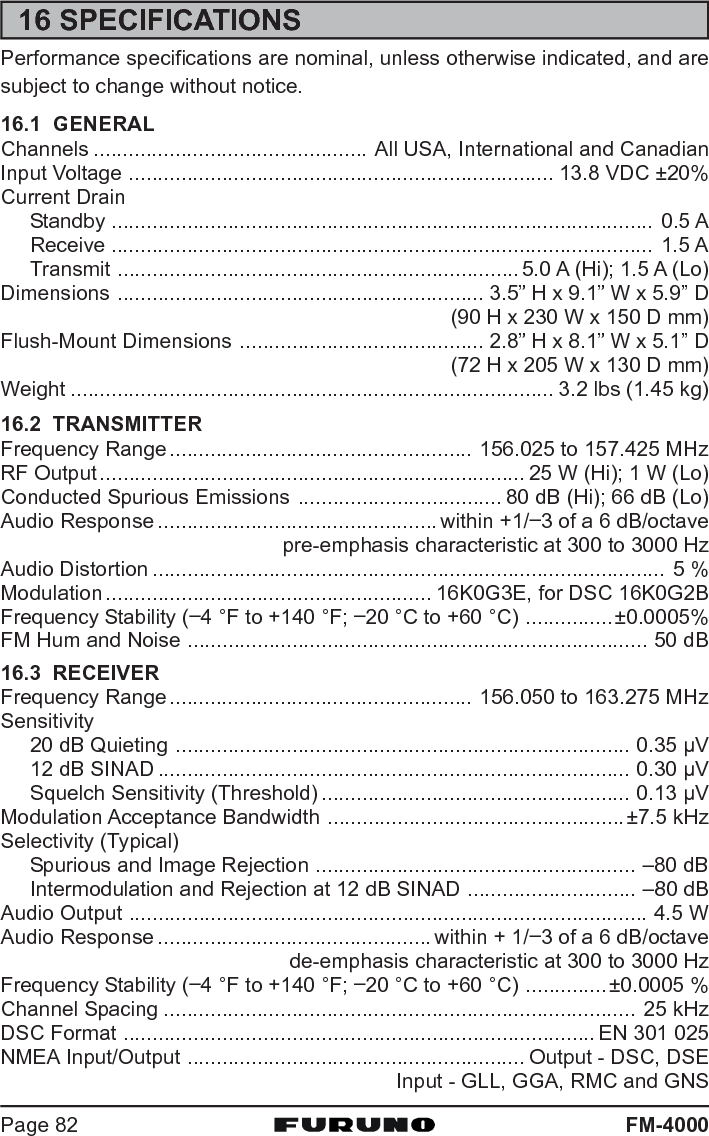
![FM-4000Page 4611.7 GROUP CALLThis feature allows the user to contact a group of specific vessels (examplemembers of a yacht club) that have DSC radios with Group call function toautomatically switch to a desired channel for voice communications.11.7.1 Setting up a Group CallFor this function to operate, the same Group MMSI must be programmed intoall the DSC VHF radios within the group of vessels that use this feature. Tounderstand about Group MMSI programming, first a Ship MMSI has to beunderstood.Ship MMSI: The first three digits called a MID (Mobile Identity Group) of a ShipMMSI denote the country the ship registered for a MMSI. The last six digits arespecific to the Ships ID.Ship MMSI Example: If your MMSI is “366123456”, for example, “366” is theMID, which denotes the country, and “123456” is the ID of your ship.Group MMSI:Group MMSI numbers are not assigned by the FCC or other organizationslicensed to assign Ship MMSI numbers.The first digit of a Group MMSI is always set to “0” in accordance withinternational regulations. All FURUNO radios are preset so when program-ming a Group MMSI the first digit is set to “0”.The USCG recommends programming the MID of a Ship MMSI into thesecond, third and fourth digits of the Group MMSI as it denotes the areathe ship is located.The last five digits are decided upon by persons in the Group. This is animportant step as all radios in the group must contain the same GroupMMSI so they can be contacted by each other. There is a chance thatanother group of vessels have the same Group MMSI as yours. If thishappens, simply change one or more of the last five digits of the GroupMMSI.1. Press and hold down the [CALL(MENU)] keyuntil the “Radio SetupRadio SetupRadio SetupRadio SetupRadio Setup” menu appears.2. Turn the CHANNEL selector knob to select the“DSC SetupDSC SetupDSC SetupDSC SetupDSC Setup” menu.3. Press the [ENT] key, then use the CHANNELselector knob to select “Group DirectoryGroup DirectoryGroup DirectoryGroup DirectoryGroup Directory.”4. Press the [ENT] key, then select “AddAddAddAddAdd” with theCHANNEL selector knob.5. Press the [ENT] key.](https://usermanual.wiki/Furuno-USA/9ZWFM4000.users-manual-part-2/User-Guide-1194863-Page-3.png)
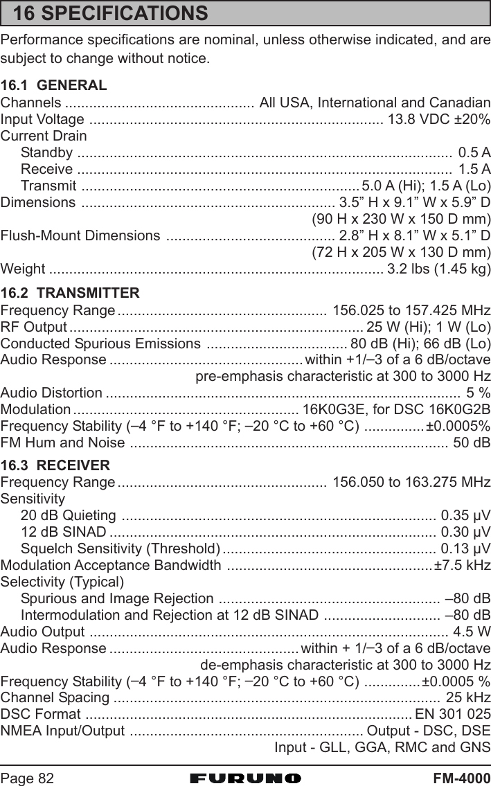
![Page 47FM-40006. Press applicable key to enter the first letter of thename of the group you want to reference in the di-rectory.Example: Press the [2(MEM)] key repeatedly totoggle among the seven available characters asso-ciated with that key: 22222 Æ AAAAA Æ BBBBB Æ CCCCC Æ aaaaa Æ bbbbb Æ ccccc Æ 22222 ....If you enter a wrong character, pres the [CLR] keyto delete the wrong character.7. Press the [ENT] key to store the first letter in the name.8. Repeat steps 6 and 7 to complete the name. The name can consist of upto 11 characters. If you do not use all 11 characters, press the [ENT] key tomove to the next space. This method can also beused to enter a blank space in the name. If you en-ter a wrong character, press the [H/L] key until thewrong character is selected, then enter the correctcharacter.9. After the 11th letter or space has been entered, press and hold the [ENT]key to advance to the Group MMSI (Maritime Mo-bile Service Identity Number) number entry.10. Enter the desired number. If you enter a wrong num-ber, press the [H/L] key until the wrong number isselected, then enter the correct number.11. To store the data entered, press and hold the [ENT]key.12. To enter another group address, repeat steps 4through 11.13. Press the [CLR] key twice to return to the “Radio SetupRadio SetupRadio SetupRadio SetupRadio Setup” menu, then pressthe [CLR] key again to return to radio operation.11.7.2 Transmitting a Group CallUsing Pre-Programmed Vessel1. Press the [CALL(MENU)] key to show the “DSCDSCDSCDSCDSCCall MenuCall MenuCall MenuCall MenuCall Menu.”2. Turn the CHANNEL selector knob to select“GroupGroupGroupGroupGroup.” (To cancel, press the [CLR] key.)3. Press the [ENT] key. The transceiver beeps,and the “Group directory” appears.4. Turn the CHANNEL selector knob to select the“Group” you want to contact.5. Press the [ENT] key, then turn the CHANNELselector knob to select the operating channel you](https://usermanual.wiki/Furuno-USA/9ZWFM4000.users-manual-part-2/User-Guide-1194863-Page-4.png)
![FM-4000Page 48want to communicate on, then press the [ENT]key.6. Press the [ENT] key again to transmit the Groupcall signal.7. When the Group call signal is sent, the LCDdisplays the information shown in the illustra-tion at right.8. After the Group call is transmitted, all the ra-dios in the group switch to the designated chan-nel.9. Listen to the channel to make sure it is not busy,then key the microphone and call the other ves-sels you desire to communicate with.Manual CallingYou may enter a Group MMSI number manually to contact a group whoseGroup call number is not registered in the radio.1. Press the [CALL(MENU)] key to show the “DSCDSCDSCDSCDSCCall MenuCall MenuCall MenuCall MenuCall Menu.”2. Turn the CHANNEL selector knob to select“GroupGroupGroupGroupGroup.” (To cancel, press the [CLR] key.)3. Press the [ENT] key. The transceiver beepsthen the “Group Directory” appears.4. Turn the CHANNEL selector knob to select“ManualManualManualManualManual,” then press the [ENT] key.5. Enter the MMSI number (nine digits: first digit per-manently set to “0”) which you want to contact, thenpress the [ENT] key.6. If you enter a wrong number in the MMSI number,press the [H/L] key until the wrong number is se-lected, then enter the correct number.7. When you have finished entering the MMSInumber, press and hold the [ENT] key.8. Turn the CHANNEL selector knob to select“ManualManualManualManualManual,” then press the [ENT] key.9. Turn the CHANNEL selector knob to select the op-erating channel you want to communicate on, thenpress the [ENT] key.10. Press the [ENT] key again to transmit the Groupcall signal.](https://usermanual.wiki/Furuno-USA/9ZWFM4000.users-manual-part-2/User-Guide-1194863-Page-5.png)
![FM-4000Page 5011.8 POSITION REQUESTAdvancements in DSC have made it possible to poll the location of anothervessel and show the position of that vessel on the display of the FM-4000.FURUNO has taken this feature one step further. If any FURUNO GPS chartplotters are connected to the FM-4000, the polled position of the vessel isshown on the display of the GPS chart plotter, making it easy to navigate to thelocation of the polled vessel. This is a great feature for anyone wanting toknow the position of another vessel. For example, your buddy that is catchingfish, or finding the location of a person you are cruising with.NOTEThe other vessel must have an operating GPS receiver connected to itsDSC transceiver and must not have its transceiver set to deny positionrequests. (See the section “11.5 INDIVIDUAL CALL” to enter informa-tion into the individual directory).11.8.1 Setting up Position ReplyThe FM-4000 can automatically or manually send your position to anothervessel. This selection is important if you are concerned about someone pollingthe position of your vessel that you may not want to. In the manual mode youwill see the MMSI or person’s name shown on the display, allowing you tochoose to send your position to the requesting vessel or not.1. Press and hold down the [CALL(MENU)] key untilthe “Radio SetupRadio SetupRadio SetupRadio SetupRadio Setup” menu appears.2. Turn the CHANNEL selector knob to select the “DSCDSCDSCDSCDSCSetupSetupSetupSetupSetup” menu.3. Press the [ENT] key, then use the CHANNEL selec-tor knob to select “Position ReplyPosition ReplyPosition ReplyPosition ReplyPosition Reply.”4. Turn the CHANNEL selector knob to select “Auto-Auto-Auto-Auto-Auto-maticmaticmaticmaticmatic” or “ManualManualManualManualManual.” In the “AutomaticAutomaticAutomaticAutomaticAutomatic” mode, after aDSC POS Request is received, the radio will auto-matically transmit your vessel’s position. In the“ManualManualManualManualManual” mode, the display of the FM-4000 will showwho is requesting your position.5. Press the [ENT] key to store the selected setting.6. Press the [CLR] key twice to return to the “RadioRadioRadioRadioRadioSetupSetupSetupSetupSetup” menu, then press the [CLR] key again to re-turn to radio operation.](https://usermanual.wiki/Furuno-USA/9ZWFM4000.users-manual-part-2/User-Guide-1194863-Page-7.png)
![Page 51FM-400011.8.2 Transmitting a Position Request to Another VesselUsing Pre-Programmed Vessel1. Press the [CALL(MENU)] key to show the “DSCDSCDSCDSCDSCCall MenuCall MenuCall MenuCall MenuCall Menu.”2. Turn the CHANNEL selector knob to select“Pos RequestPos RequestPos RequestPos RequestPos Request.”3. Press [ENT] key to show the Position RequestDirectory. This directory uses the Individual Di-rectory information.4. Turn the CHANNEL selector knob to select aname, then press the [ENT] key.5. Press the [ENT] key again to transmit the Po-sition Request DSC call.6. When the FM-4000 receives the position fromthe polled vessel it is shown on the radio dis-play and also transferred to the GPS chart plot-ter.NOTEIf the FM-4000 does not receive position data from the polled vessel,the LCD shows “NO POSITION DATA.”Manual RequestYou may enter an MMSI number manually to request the position of a vesselthat is not registered in the Setting up the Individual / Position Call Directory.1. Press the [CALL(MENU)] key to show the “DSCDSCDSCDSCDSCCall MenuCall MenuCall MenuCall MenuCall Menu.”2. Turn the CHANNEL selector knob to select“Pos RequestPos RequestPos RequestPos RequestPos Request.”3. Press the [ENT] key to show the Position Re-quest directory. This directory uses the Indi-vidual Directory information.4. Turn the CHANNEL selector knob to select“ManualManualManualManualManual,” then press the [ENT] key.5. Enter the MMSI number (nine digits) which youwant to contact by the keypad, then press the[ENT] key.6. If you enter a wrong number in the MMSI num-ber, press the [H/L] key until the wrong num-](https://usermanual.wiki/Furuno-USA/9ZWFM4000.users-manual-part-2/User-Guide-1194863-Page-8.png)
![FM-4000Page 52ber is selected, then enter the correct number.7. When you have finished entering the MMSI num-ber, press and hold the [ENT] key.8. Press the [ENT] key to transmit the PositionRequest DSC call.9. When the FM-4000 receives the position fromthe polled vessel it is shown on the radio dis-play and also transferred to the GPS chart plot-ter.11.8.3 Receiving a Position RequestWhen a Position Request call is received from another vessel, a ringing alarmwill sound and “POS REQUESTPOS REQUESTPOS REQUESTPOS REQUESTPOS REQUEST” appears. Operation and transceiver functiondiffer depending on the “Position ReplyPosition ReplyPosition ReplyPosition ReplyPosition Reply” setting in the “DSC SetupDSC SetupDSC SetupDSC SetupDSC Setup” menu.Automatically reply:1. When a Position Request call is received, a calling alarm sounds four times.Then requested position coordinates are transmit-ted automatically to the vessel requesting yourvessel’s position.2. To exit from the Position Request display, pressthe [CLR] key.Manually reply:1. When a Position Request call is received from an-other vessel, the LCD shows the time and MMSI orname of person requesting your vessel’s position.2. A ringing alarm sounds four times. To send yourvessel’s position to the requesting vessel, press the [ENT] key. Or to exitfrom Position Request display, press the [CLR] key.](https://usermanual.wiki/Furuno-USA/9ZWFM4000.users-manual-part-2/User-Guide-1194863-Page-9.png)
![Page 53FM-400011.9 POSITION SENDThe feature is similar to Position Request, however instead of requesting aposition of another vessel this function allows you to send your position toanother vessel. Your vessel must have an operating GPS receiver connectedto the FM-4000 to send your position.NOTETo transmit a Position Send call, you must set up the FM-4000 DSCIndividual / Position Call Directory with the name of the vessel(s) orperson and the MMSI of the DSC radio you wish to send your positionto. To setup this directory, see section “11.5.1 Setting up the Individual/ Position Call Directory.”11.9.1 Setting up a Position Send RingerThe FM-4000 has the capability to turn off the Position Send ringer as follows.1. Press and hold down the [CALL(MENU)] keyuntil the “Radio SetupRadio SetupRadio SetupRadio SetupRadio Setup” menu appears.2. Turn the CHANNEL selector knob to select the“DSC SetupDSC SetupDSC SetupDSC SetupDSC Setup” menu.3. Press the [ENT] key, then use the CHANNELselector knob to select “DSC BeepDSC BeepDSC BeepDSC BeepDSC Beep.”4. Press the [ENT] key, then use the CHANNELselector knob to select “Position ReportPosition ReportPosition ReportPosition ReportPosition Report.”5. Press the [ENT] key, then select “OffOffOffOffOff” with theCHANNEL selector knob.6. Press the [ENT] key to store the selected set-ting.7. Press the [CLR] key twice to return to the “RadioRadioRadioRadioRadioSetupSetupSetupSetupSetup” menu, then press the [CLR] key again to re-turn to radio operation.To enable the ringer tone, select “OnOnOnOnOn” at step “6” in this procedure.11.9.2 Transmitting a DSC Position Send CallUsing Pre-Programmed Vessel1. Press the [CALL(MENU)] key to show the “DSCDSCDSCDSCDSCCall MenuCall MenuCall MenuCall MenuCall Menu.”2. Turn the CHANNEL selector knob to select“Pos ReportPos ReportPos ReportPos ReportPos Report.”](https://usermanual.wiki/Furuno-USA/9ZWFM4000.users-manual-part-2/User-Guide-1194863-Page-10.png)
![FM-4000Page 543. Press [ENT] key to show the Position Send Di-rectory. This directory uses the Individual Di-rectory information.4. Turn the CHANNEL selector knob to select aname in the directory, then press the [ENT] key.5. Press the [ENT] key again to send your posi-tion to the selected vessel.6. Press the [CLR] key twice to return to the “Ra-Ra-Ra-Ra-Ra-dio Setupdio Setupdio Setupdio Setupdio Setup” menu, then press the [CLR] keyagain to return to radio operation.Manual CallingYou may enter an MMSI number manually to send your position to that vesselwithout entering it into the Setting up the Individual / Position Call Directory.1. Press the [CALL(MENU)] key to show the “DSCDSCDSCDSCDSCCall MenuCall MenuCall MenuCall MenuCall Menu.”2. Turn the CHANNEL selector knob to select“Pos ReportPos ReportPos ReportPos ReportPos Report.”3. Press [ENT] key to show the Position SendDirectory. This directory uses the IndividualDirectory information.4. Turn the CHANNEL selector knob to select“ManualManualManualManualManual,” then press the [ENT] key.5. Enter the MMSI number (nine digits: first digitpermanently set to “0”) which you want to con-tact, then press the [ENT] key.6. If you enter a wrong number in the MMSI num-ber, press the [H/L] key until the wrong number isselected, then enter the correct number.7. When you have finished entering the MMSI num-ber, press and hold the [ENT] key.8. Press the [ENT] key to send your position to theselected vessel.](https://usermanual.wiki/Furuno-USA/9ZWFM4000.users-manual-part-2/User-Guide-1194863-Page-11.png)
![Page 55FM-400011.9.3 Receiving a DSC Position Send CallWhen another vessel transmits its location to the FM-4000, the following oc-curs:1. A ringing sound is generated when the call is received.2. Press any key to stop the ringing sound.3. The position of the vessel is shown and also trans-ferred to any FURUNO GPS chart plotter if con-nected.11.10 MANUAL INPUT OF POSITION (LAT/LON)You may send the latitude/longitude of your vessel manually when the FM-4000 is not connected to a GPS receiver.After the position is entered, any DSC Distress, Position Request, or PositionSend will contain the manually entered position.1. Press and hold down the [CALL(MENU)] keyuntil the “Radio SetupRadio SetupRadio SetupRadio SetupRadio Setup” menu appears.2. Turn the CHANNEL selector knob to select the“DSC SetupDSC SetupDSC SetupDSC SetupDSC Setup” menu.3. Press the [ENT] key, then use the CHANNELselector knob to select “Position InputPosition InputPosition InputPosition InputPosition Input.”4. Press the [ENT] key. The transceiver beeps,then the display looks something like the onein the illustration at right.5. Enter your local UTC time in the 24-hour notation,then press the [ENT] key.6. Enter the latitude/longitude of your vessel, then pressthe [ENT] key. To select North (N) press the [6(NAV)]key, South (S) press the [7(SCRM)] key, East (E)press the [3(SCAN)] key or West (W) press the[9(FOG)] key.7. To store the data entered, press and hold the [ENT]key.8. Press the [CLR] key twice to return to the “RadioRadioRadioRadioRadioSetupSetupSetupSetupSetup” menu, then press the [CLR] key again to return to radio operation.](https://usermanual.wiki/Furuno-USA/9ZWFM4000.users-manual-part-2/User-Guide-1194863-Page-12.png)
![FM-4000Page 5612 RADIO SETUPNOTEThe optional CMP30 Remote MIC can also access the SETUP menu.See page 73 for details.12.1 LCD CONTRASTAdjust the LCD contrast for best viewability.1. Press and hold down the [CALL(MENU)] key until“Radio SetupRadio SetupRadio SetupRadio SetupRadio Setup” menu appears.2. Press the [ENT] key, then use the CHANNEL selec-tor knob to select “ContrastContrastContrastContrastContrast.”3. Press the [ENT] key.4. Turn the CHANNEL selector knob to select the de-sired level. The contrast level can be set from “00000” to“3131313131.”5. Press the [ENT] key to store the selected level.6. To exit this menu and return to radio operation mode,press the [16/9] key.](https://usermanual.wiki/Furuno-USA/9ZWFM4000.users-manual-part-2/User-Guide-1194863-Page-13.png)
![Page 57FM-400012.2 TIME OFFSET“Time Offset” sets the time offset between local time and UTC in order to dis-play local time. The time display requires connection of a GPS receiver.1. Press and hold down the [CALL(MENU)] key untilthe “Radio SetupRadio SetupRadio SetupRadio SetupRadio Setup” menu appears.2. Press the [ENT] key, then use the CHANNEL selec-tor knob to select “Time OffsetTime OffsetTime OffsetTime OffsetTime Offset.”3. Press the [ENT] key.4. Turn the CHANNEL selector knob to select time off-set from UTC. See the illustration below to find youroffset time from UTC. If “0:000:000:000:000:00” is assigned, the timeis the same as UTC (Universal Time Coordinated orGMT Greenwich Mean Time).5. Press the [ENT] key to store the time offset.6. To exit this menu and return to radio operation mode,press the [16/9] key.OFFSET TIME TABLE](https://usermanual.wiki/Furuno-USA/9ZWFM4000.users-manual-part-2/User-Guide-1194863-Page-14.png)
![FM-4000Page 5812.3 TIME DISPLAYThe time can be shown in local or UTC time. The time display requires con-nection of a GPS receiver.1. Press and hold down the [CALL(MENU)] key untilthe “Radio SetupRadio SetupRadio SetupRadio SetupRadio Setup” menu appears.2. Press the [ENT] key, then use the CHANNEL selec-tor knob to select “Time DisplayTime DisplayTime DisplayTime DisplayTime Display.”3. Press the [ENT] key.4. Turn the CHANNEL selector knob to select “UTCUTCUTCUTCUTC” or“LocalLocalLocalLocalLocal.”5. Press the [ENT] key to store the selected setting.6. To exit this menu and return to radio operation mode,press the [16/9] key.In the local time mode, the display shows the time bythe 12-hour system, while the display shows the time by the 24-hour system inthe UTC mode.12.4 SOG (SPEED OVER GROUND) UNITThe SOG indication can be shown in knot, mph or kph.1. Press and hold down the [CALL(MENU)] key untilthe “Radio SetupRadio SetupRadio SetupRadio SetupRadio Setup” menu appears.2. Press the [ENT] key, then use the CHANNEL selec-tor knob to select “SOG UnitSOG UnitSOG UnitSOG UnitSOG Unit.”3. Press the [ENT] key.4. Turn the CHANNEL selector knob to select desiredunit.5. Press the [ENT] key to store the selected setting.6. To exit this menu and return to radio operation mode,press the [16/9] key.(“LOCAL” mode)(“UTC” mode)](https://usermanual.wiki/Furuno-USA/9ZWFM4000.users-manual-part-2/User-Guide-1194863-Page-15.png)
![Page 59FM-400012.5 TRUE MAGNETIC CHANGE (NAV DISPLAY)The GPS COG (Course Over Ground) indication can be shown in True orMagnetic.1. Press and hold down the [CALL(MENU)] key untilthe “Radio SetupRadio SetupRadio SetupRadio SetupRadio Setup” menu appears.2. Press the [ENT] key, then use the CHANNEL selec-tor knob to select “MagneticMagneticMagneticMagneticMagnetic.”3. Press the [ENT] key.4. Turn the CHANNEL selector knob to select “Mag-Mag-Mag-Mag-Mag-neticneticneticneticnetic” or “TrueTrueTrueTrueTrue.”5. Press the [ENT] key to store the selected setting.6. To exit this menu and return to radio operation mode,press the [16/9] key.12.6 PRIORITY CHANNELYou can set the priority channel to use when priority scan is enabled.1. Press and hold down the [CALL(MENU)] key untilthe “Radio SetupRadio SetupRadio SetupRadio SetupRadio Setup” menu appears.2. Press the [ENT] key, then use the CHANNEL selec-tor knob to select “Priority CHPriority CHPriority CHPriority CHPriority CH.”3. Press the [ENT] key.4. Turn the CHANNEL selector knob to select the chan-nel to be a priority.5. Press the [ENT] key to store the selected setting.6. To exit this menu and return to radio operation mode,press the [16/9] key.](https://usermanual.wiki/Furuno-USA/9ZWFM4000.users-manual-part-2/User-Guide-1194863-Page-16.png)
![FM-4000Page 6012.7 SCAN TYPEYou can set the scan mode between “Memory Scan” and “Priority Scan.”1. Press and hold down the [CALL(MENU)] key untilthe “Radio SetupRadio SetupRadio SetupRadio SetupRadio Setup” menu appears.2. Press the [ENT] key, then use the CHANNEL selec-tor knob to select “SCAN TypeSCAN TypeSCAN TypeSCAN TypeSCAN Type.”3. Press the [ENT] key.4. Turn the CHANNEL selector knob to select “PriorityPriorityPriorityPriorityPrioritySCANSCANSCANSCANSCAN” or “Memory SCANMemory SCANMemory SCANMemory SCANMemory SCAN.”5. Press the [ENT] key to store the selected setting.6. To exit this menu and return to radio operation mode,press the [16/9] key.12.8 SCAN RESUME TIMESet the amount of time the FM-4000 waits after a transmission ends beforestarting scanning.1. Press and hold down the [CALL(MENU)] key untilthe “Radio SetupRadio SetupRadio SetupRadio SetupRadio Setup” menu appears.2. Press the [ENT] key, then use the CHANNEL selec-tor knob to select “SCAN ResumeSCAN ResumeSCAN ResumeSCAN ResumeSCAN Resume.”3. Press the [ENT] key.4. Turn the CHANNEL selector knob to select the de-sired resume time. The resume time can be set to“1sec1sec1sec1sec1sec” through “5sec5sec5sec5sec5sec,” or “OffOffOffOffOff.” In the “OffOffOffOffOff” selection,the scanning resumes after the other station stopstransmitting (carrier drops).5. Press the [ENT] key to store the selected setting.6. To exit this menu and return to radio operation mode,press the [16/9] key.](https://usermanual.wiki/Furuno-USA/9ZWFM4000.users-manual-part-2/User-Guide-1194863-Page-17.png)
![Page 61FM-400012.9 KEY BEEPSet the beep tone volume level when a key is pressed.1. Press and hold down the [CALL(MENU)] key untilthe “Radio SetupRadio SetupRadio SetupRadio SetupRadio Setup” menu appears.2. Press the [ENT] key, then use the CHANNEL selec-tor knob to select “Key BeepKey BeepKey BeepKey BeepKey Beep.”3. Press the [ENT] key.4. Turn the CHANNEL selector knob to select the de-sired level. The beep can be set from “Level 1Level 1Level 1Level 1Level 1” to“Level 6Level 6Level 6Level 6Level 6,” “HighHighHighHighHigh,” or “OffOffOffOffOff.”5. Press the [ENT] key to set the key beep condition.6. To exit this menu and return to radio operation mode,press the [16/9] key.NOTEEmergency alarm and beeps for DSC operation cannot be turned OFF.12.10 WEATHER ALERT SETUPThe NOAA Weather alert can be enabled or disabled. The default setting is“On SCAN and WX CH.”1. Press and hold down the [CALL(MENU)] key untilthe “Radio SetupRadio SetupRadio SetupRadio SetupRadio Setup” menu appears.2. Press the [ENT] key, then use the CHANNEL selec-tor knob to select “Weather AlertWeather AlertWeather AlertWeather AlertWeather Alert.”3. Press the [ENT] key.4. Turn the CHANNEL selector knob to select the de-sired WX alert mode. The WX alert mode can beset to “On WX CHOn WX CHOn WX CHOn WX CHOn WX CH,” “On SCANOn SCANOn SCANOn SCANOn SCAN,” “On SCAN andOn SCAN andOn SCAN andOn SCAN andOn SCAN and WXWXWXWXWXCHCHCHCHCH,” or “OffOffOffOffOff.”5. Press the [ENT] key to store the selected setting.6. To exit this menu and return to radio operation mode,press the [16/9] key.](https://usermanual.wiki/Furuno-USA/9ZWFM4000.users-manual-part-2/User-Guide-1194863-Page-18.png)
![FM-4000Page 6212.11 CHANNEL NAMINGYou may change the name of a channel.Example: CH84 “CALL HOME”1. Press and hold down the [CALL(MENU)] key untilthe “Radio SetupRadio SetupRadio SetupRadio SetupRadio Setup” menu appears.2. Press the [ENT] key, then use the CHANNEL selec-tor knob to select “CH NameCH NameCH NameCH NameCH Name.3. Press the [ENT] key.4. Turn the CHANNEL selector knob to select the chan-nel to name, then press the [ENT] key.5. Press applicable key to enter the first letter of thechannel name.Example: Press the [4(GHI)] key repeatedly to toggleamong the seven available characters associatedwith that key: 44444 Æ GGGGG Æ HHHHH Æ IIIII Æ ggggg Æ hhhhh Æ iiiii Æ 22222 ....6. Press the [ENT] key to enter the desired letter andmove the cursor one space to the right.7. Repeat steps 5 and 6 to complete the name. Thename can consist of up to 16 characters. If you donot use all 16 characters, press the [ENT] key tomove to the next space. This method can also beused to enter a blank space in the name. To clearthe previous letter, press the [CLR] key.8. Press and hold down the [ENT] key to enter thename.9. If you want to change the name of another channel,repeat steps 3 through 8.10. To exit this menu and return to radio operation mode, press the [16/9] key.](https://usermanual.wiki/Furuno-USA/9ZWFM4000.users-manual-part-2/User-Guide-1194863-Page-19.png)
![Page 63FM-400012.12 NAMING THE RADIO OR REMOTE MICYou can change the name of the RADIO or Remote MIC. Example: “RADIO -Cabin,” “RAM1 - Flybridge.”1. Press and hold down the [CALL(MENU)] key untilthe “Radio SetupRadio SetupRadio SetupRadio SetupRadio Setup” menu appears.2. Press the [ENT] key, then use the CHANNEL selec-tor knob to select “Unit NameUnit NameUnit NameUnit NameUnit Name.”3. Press the [ENT] key.4. With the Remote MIC connected, turn the CHAN-NEL selector knob to select the Unit (“RadioRadioRadioRadioRadio” or“RAM1RAM1RAM1RAM1RAM1”) to name, then press the [ENT] key, other-wise press the [ENT] key.5. Press applicable key to enter the first letter of chan-nel name.Example: Press the [2(MEM)] key repeatedly totoggle among the seven available characters asso-ciated with that key: 22222 Æ AAAAA Æ BBBBB Æ CCCCC Æ aaaaa Æ bbbbb Æ ccccc Æ 22222 ....6. Press the [ENT] key to enter the first letter in thename and move to the next letter to the right.7. Repeat steps 5 and 6 to complete the name. Thename can consist of up to eight characters. If youdo not use all eight characters press the [ENT] keyto move to the next space. This method can also be used to enter a blankspace in the name. To clear the previous letter, press the [CLR] key.8. Press and hold the [ENT] key to enter the name and return to the “UnitUnitUnitUnitUnitNameNameNameNameName” menu.9. If you want to enter the name of another unit, repeat steps 4 through 8.10. To exit this menu and return to radio operation mode, press the [16/9] key.](https://usermanual.wiki/Furuno-USA/9ZWFM4000.users-manual-part-2/User-Guide-1194863-Page-20.png)
![FM-4000Page 6412.13 ADJUSTING THE TREBLE AND BASSAdjust the treble and bass of the speaker audio for best listening in noisyenvironments. The effect is similar to adjusting the treble and bass controls ona stereo.1. Press and hold down the [CALL(MENU)] keyuntil “Radio SetupRadio SetupRadio SetupRadio SetupRadio Setup” menu appears.2. Press the [ENT] key, then use the CHANNELselector knob to select “Tone ControlTone ControlTone ControlTone ControlTone Control.”3. Press the [ENT] key, then select “BassBassBassBassBass” with theCHANNEL selector knob.4. Press the [ENT] key, then turn the CHANNELselector knob to select desired audio responsein the lower frequency range. Available selec-tions are “–––––66666” through “+6+6+6+6+6.”5. Press the [ENT] key to store the selected setting.6. Select “TrebleTrebleTrebleTrebleTreble” with the CHANNEL selectorknob, then press the [ENT] key.7. Turn the CHANNEL selector knob to select de-sired audio response in the higher frequencyrange. Available selections are “–––––66666” through“+6+6+6+6+6.”8. Press the [ENT] key to store the selected setting.9. To exit this menu and return to radio operation mode, press the [16/9] key.12.14 FOG ALERT TONE FREQUENCYYou can select the tone frequency for the PA/Fog operation. The availablefrequency range is 200 Hz - 850 Hz, in 50 Hz steps. The default tone fre-quency is 400 Hz.1. Press and hold down the [CALL(MENU)] key untilthe “Radio SetupRadio SetupRadio SetupRadio SetupRadio Setup” menu appears.2. Press the [ENT] key, then use the CHANNEL selec-tor knob to select “FOG FrequencyFOG FrequencyFOG FrequencyFOG FrequencyFOG Frequency..3. Press the [ENT] key.4. Turn the CHANNEL selector knob to select desiredtone frequency.5. Press the [ENT] key to store the selected setting.6. To exit this menu and return to radio operation mode,press the [16/9] key.](https://usermanual.wiki/Furuno-USA/9ZWFM4000.users-manual-part-2/User-Guide-1194863-Page-21.png)
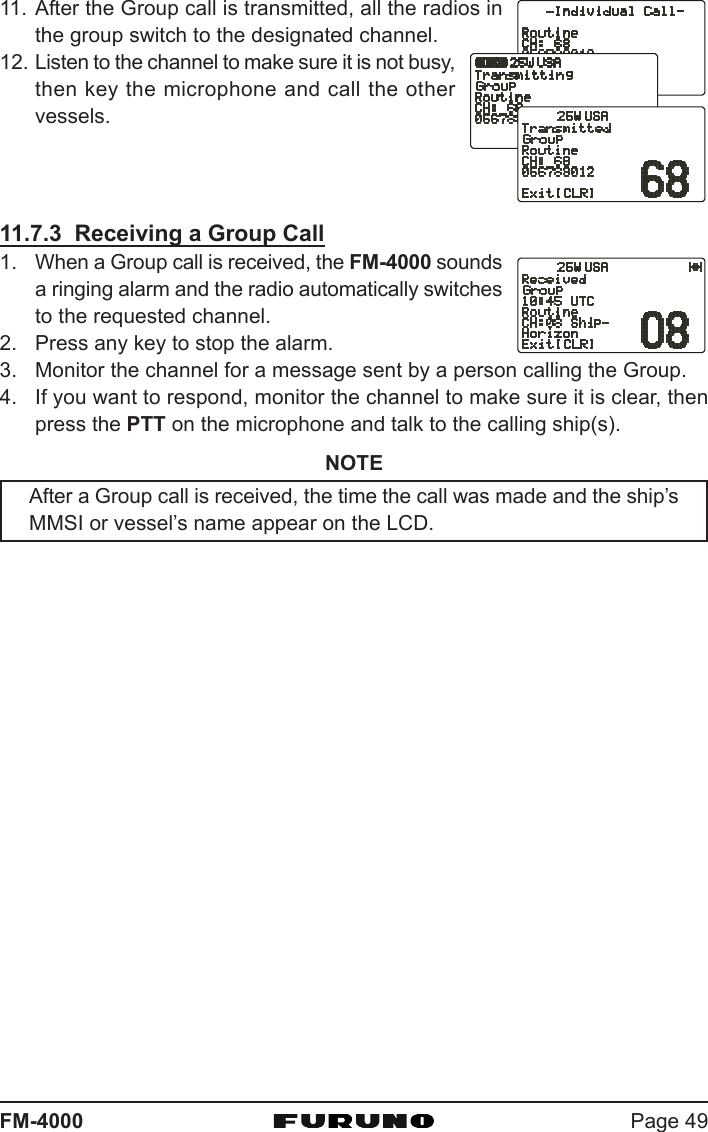
![FM-4000Page 66Examples:NOTEIf you are west of UTC time you will add the offset to your time.If you are East of UTC time you will subtract the offset from your time.1. Press and hold the [CALL(MENU)] key until the “Ra-Ra-Ra-Ra-Ra-dio Setupdio Setupdio Setupdio Setupdio Setup” menu appears.2. Press the [ENT] key3. Select “CalendarCalendarCalendarCalendarCalendar” with the CHANNEL selector knob.4. Press the [ENT] key5. Select “Date Date Date Date Date (20YY20YY20YY20YY20YY/MMMMMMMMMM/DDDDDDDDDD)” with the CHANNEL se-lector knob.6. Press the [ENT] key.7. Enter the current date (Yr/Mo/Day).8. If you enter a wrong number, press the [H/L] keyuntil the wrong number is selected, then enter thecorrect number.9. Using the Standard time table above, calculate theUTC time of your position.Note: For daylight savings time subtract one hourto the offset in your time zone.10. To enter the time, press the [ENT] key until the firstdigit in the “Time Time Time Time Time (hhhhhhhhhh/mm [UTC]mm [UTC]mm [UTC]mm [UTC]mm [UTC])” is selected on thedisplay, then enter the time.11. Press and hold down the [ENT] key to store the se-lected setting.12. Select “UpdateUpdateUpdateUpdateUpdate” with the CHANNEL selector knob,then press the [ENT] key.City NYOffset -5Time (convert local time to 24 hour) 4:00PM (local) or 16:00 (24hour)Calculate 24hour local + Offset (East of UTC) 16:00 + 05:00 = 21:00City RomeOffset +1Time (convert local time to 24 hour) 4:00PM (local) or 16:00 (24hour)Calculate 24hour local + Offset (East of UTC) 16:00 - 01:00 = 15:00City Los AngelesOffset -8Time (convert local time to 24 hour) 4:00PM (local) or 16:00 (24hour)Calculate 24hour local + Offset (East of UTC) 16:00 + 08:00 = 22:00](https://usermanual.wiki/Furuno-USA/9ZWFM4000.users-manual-part-2/User-Guide-1194863-Page-23.png)
![Page 67FM-400013. Turn the CHANNEL selector knob to select themethod of the time adjustment between “AutomaticAutomaticAutomaticAutomaticAutomatic”and “ManualManualManualManualManual.”14. Press the [ENT] key to store the selected setting.15. To exit this menu and return to radio operation mode, press the [16/9] key.](https://usermanual.wiki/Furuno-USA/9ZWFM4000.users-manual-part-2/User-Guide-1194863-Page-24.png)
![FM-4000Page 6813 REMOTE MIC OPERATIONWhen the Remote MIC is connected to the FM-4000, most VHF, DSC, setupmenus and PA modes can be remotely operated. The Remote MIC is suppliedwith 23 feet (7 m) of routing cable and can be extended up to 70 feet (21 m)using three 23-foot extension cables model CT-100. The Intercom feature canbe used between the Remote MIC and the transceiver. In addition, speakerwires are supplied at the panel mount of the routing cable for external speak-ers to be connected in noisy environments.13.1 REMOTE MIC CONTROLS[H/L] KEYToggles between high and low power. When the [H/L] key is pressed whilethe transceiver is on CH13 or CH67, the power is temporarily switchedfrom LO to HI until the PTT switch is released. The [H/L] key does notfunction on transmit inhibited and low-power only channels.PTT (Push-To-Talk) KeyActivates transmission.](https://usermanual.wiki/Furuno-USA/9ZWFM4000.users-manual-part-2/User-Guide-1194863-Page-25.png)
![Page 69FM-4000POWER ( ) KeyPress and hold down this key to turn to the transceiver and Remote MICon or off.MICROPHONEThe internal microphone is located here.When transmitting, position your mouth about 1/2 to 1 inch (1.2 ~ 2.5 cm)away from the small mic hole. Speak slowly and clearly into the micro-phone.DISPLAYChannel display.SOFT KEYThese three key’s functions can be customized by the Setup Menu mode.When press one of these key briefly, the key functions will appear at theLCD bottom. The factory defaults are shown below.[SCAN] KeyStarts and stops scanning of programmed channels.[DW] KeyWatches for a transmission on CH16 and another selected channel untileither signal is received. (Dual watch)[IC] KeyGet Intercom operation between radio and the Remote MIC.KEY PAD[CALL/MENU] KeyPress this key to access the DSC OPERATION menu.Press and hold this key to access the SETUP menu.[16/9] KeyFirst press: channel 16 is immediately selected.Second press: recalls the last selected channel.Press and hold: selects channel 9.[S](UP)/[T](DOWN) KeyThese keys are used to select channels, adjust the volume and squelchlevel, and to choose DSC calls, DSC setup and Radio setup function.[VOL/SQ] Key (Volume Control / Squelch Control)Press this key to toggle the function of the Remote MIC’s [S] or [T] keybetween the channel selections, volume level adjustment, and squelchlevel adjustment.](https://usermanual.wiki/Furuno-USA/9ZWFM4000.users-manual-part-2/User-Guide-1194863-Page-26.png)
![FM-4000Page 70[CLR/WX] KeyImmediately recalls the previously selected NOAA weather channel.Cancel the menu selection and/or keypad entry.Secondary useHold down the [16/9] key while pressing the [WX] key to change themode from USA to International or Canadian.[ENT] KeyThis key functions as the enter key.SPEAKERThe internal speaker is located here.[DISTRESS] KEYUsed to send a DSC Distress call.13.2 INTERCOM OPERATION13.2.1 Communication1. Press one of the Soft key briefly to appear the key functions at the LCDbottom, then press the [IC] key to activate the “Intercom” mode.2. If your FM-4000 is equipped with two Remote MICs, use the [T]/[S] key toselect the station (RADIORADIORADIORADIORADIO, RAMRAMRAMRAMRAM, or ALLALLALLALLALL) you wish tocommunicate with, then press the [ENT] key.3. When the “Intercom” feature is activated, “IntercomIntercomIntercomIntercomIntercom”appears on the FM-4000 and CMP30.4. Press the PTT switch and“TALK” is displayed.NOTE: A warning beep is emit-ted when the Remote MIC’sPTT switch is pressed whilethe transceiver microphone’sPTT switch is pressed.5. Speak slowly and clearly intothe microphone, holding themicrophone about 1/2 inchaway from your mouth.6. When finished, release thePTT switch.7. Press the [CLR(WX)] keyagain to revert to the “RADIO” mode.(FM-4000 display)(CMP30 display)(FM-4000’s PTT switch is pressed)(CMP30’s PTT switch is pressed)](https://usermanual.wiki/Furuno-USA/9ZWFM4000.users-manual-part-2/User-Guide-1194863-Page-27.png)
![Page 71FM-400013.2.2 CallingPress and hold the [DW(IC)] key for one second when the “Intercom” mode isactive. A calling beep is emitted from the speaker.13.3 KEY ASSIGNMENT13.3.1 Number of Soft KeysThree soft keys are set as default. However the Remote MIC allows assigningof up to six soft keys with the instructions below:1. Press and hold down the [CALL(MENU)] keyuntil “Radio SetupRadio SetupRadio SetupRadio SetupRadio Setup” menu appears.2. Press the [ENT] key, then press the [T] keyto select “SOFT KeysSOFT KeysSOFT KeysSOFT KeysSOFT Keys.”3. Press the [ENT] key.4. Press the [S] or [T] key to select “Number ofNumber ofNumber ofNumber ofNumber ofSOFT KeysSOFT KeysSOFT KeysSOFT KeysSOFT Keys” and press the [ENT] key.5. Press the [S] or [T] key to select the numberof soft keys (33333, 44444, or 66666) and press the [ENT]key.6. To exit this menu and return to radio operation mode,press the [16/9] key.](https://usermanual.wiki/Furuno-USA/9ZWFM4000.users-manual-part-2/User-Guide-1194863-Page-28.png)
![FM-4000Page 7213.3.2 Define the Soft KeysBy default the soft keys are assigned as SCAN, DW and NAV, however theirfunction can be changed. In addition the soft keys can be increased or reas-signed as follows:1. Press and hold down the [CALL(MENU)] keyuntil “Radio SetupRadio SetupRadio SetupRadio SetupRadio Setup” menu appears.2. Press the [ENT] key, then press the [T] keyto select “SOFT KeysSOFT KeysSOFT KeysSOFT KeysSOFT Keys.”3. Press the [ENT] key.4. Press the [T] key to select “Define Define Define Define Define [[[[[SOFTSOFTSOFTSOFTSOFT]]]]] Keys Keys Keys Keys Keys”and press the [ENT] key.5. Press the [S] or [T] key to select the [Soft]key, and press the [ENT] key. Then, press the[S] or [T] key to select the new function tobe assigned, and press the [ENT] key. Avail-able functions are listed below.6. To exit this menu and return to radio opera-tion mode, press the [16/9] key.13.4 EXTERNAL SPEAKER AF SELECTIONThe “AF SelectAF SelectAF SelectAF SelectAF Select” menu allows you to set the audio output level of the RemoteMIC’s External Speaker to a fixed level regardless of the VOL level setting ofthe Remote MIC, which is useful when using the amplified speaker (not op-tion) with on/off volume control.1. Press and hold down the [CALL(MENU)] keyuntil “Radio SetupRadio SetupRadio SetupRadio SetupRadio Setup” menu appears.2. Press the [ENT] key, then use the [S]/[T] keyto select “AF SelectAF SelectAF SelectAF SelectAF Select.”3. Press the [ENT] key.4. Press the [S] or [T] key to select “PrPrPrPrPr” (ExternalSpeaker Level is “Fixed”) or “PoPoPoPoPo” (External SpeakerLevel is “Adjustable”).5. Press the [ENT] key to store the data entered, thenpress the [16/9] key to exit this menu and return to radio operation mode.DISPLAYSCANDWMEMICPAFOGSCRMFUNCTIONStops and starts scanning.Stops and starts Dual Watch Scan.When pressed memorizes a channel for scanning.Activates the Intercom function.Operates the PA function.Operates the Fog Horn function.Toggles the Voice Scrambler “on” and “off”.](https://usermanual.wiki/Furuno-USA/9ZWFM4000.users-manual-part-2/User-Guide-1194863-Page-29.png)
![Page 73FM-400013.5 DSC/RADIO SETUP MODEThe Remote MIC can access the DSC SETUP / RADIO SETUP menu (seesection “11 DIGITAL SELECTIVE CALLING” and section “12 RADIO SETUPMENU” for details). However, the Dimmer, Contrast, and Key Beep menu itemswhich are accessed from the Remote MIC only controls the Remote MIC’sdisplay and speaker.DSC SETUP /RADIO SETUP menu from the Remote MIC:1. Press and hold down the [CALL(MENU)] key until“Radio SetupRadio SetupRadio SetupRadio SetupRadio Setup” menu appears.2. Press the [S]/[T] key to select “Radio SetupRadio SetupRadio SetupRadio SetupRadio Setup” or “DSCDSCDSCDSCDSCSetupSetupSetupSetupSetup.”3. Press the [ENT] key, then use the [S]/[T] key toselect the menu item you wish to work on.4. Press the [ENT] key.5. Press the [S]/[T] key to change the value or condi-tion for the menu item, then press the [ENT] key tosave the new setting.6. Press the [16/9] key to return to the normal opera-tion.DSC SETUP FunctionIndividual Directory Sets the Individual Directory.Individual Reply Sets how to reply to an Individual call, Automatic or Manual.Individual Ack Sets how to acknowledge an Individual call, Able or Unable.Individual Ringer Selects individual call ringer tone, among four choices.Group Directory Setup the Group Directory.Position Reply Selects how to respond to request for your position, Automatic or Manual.Position Input Sets the latitude/longitude of your vessel manually.DSC BEEP Turns on or off the Individual, Group, Position request or send beep.Radio Setup FunctionDimmer Adjusts the backlight.Contrast Adjusts display contrast.SOG Unit Selects SOC unit, knots, MPH or KPH.Magnetic Selects COG indication format, True or Magnetic.Key Beep Turns key beep on or off.Unit Name Allows changing the name of the connected MIC.EXT Speaker Selects the speaker to use, Internal or External.AF Select Selects the audio output,Soft Keys Sets the key assignment.](https://usermanual.wiki/Furuno-USA/9ZWFM4000.users-manual-part-2/User-Guide-1194863-Page-30.png)