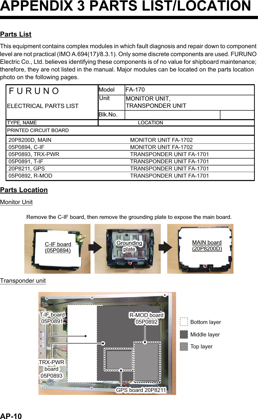
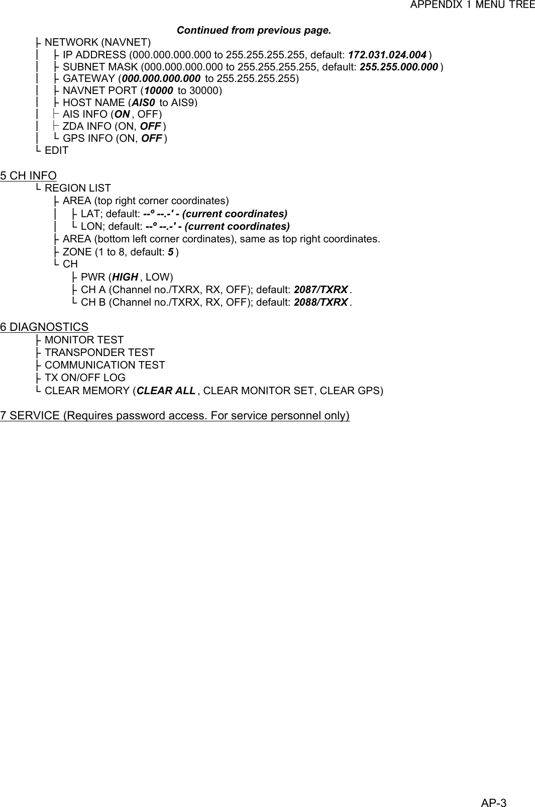
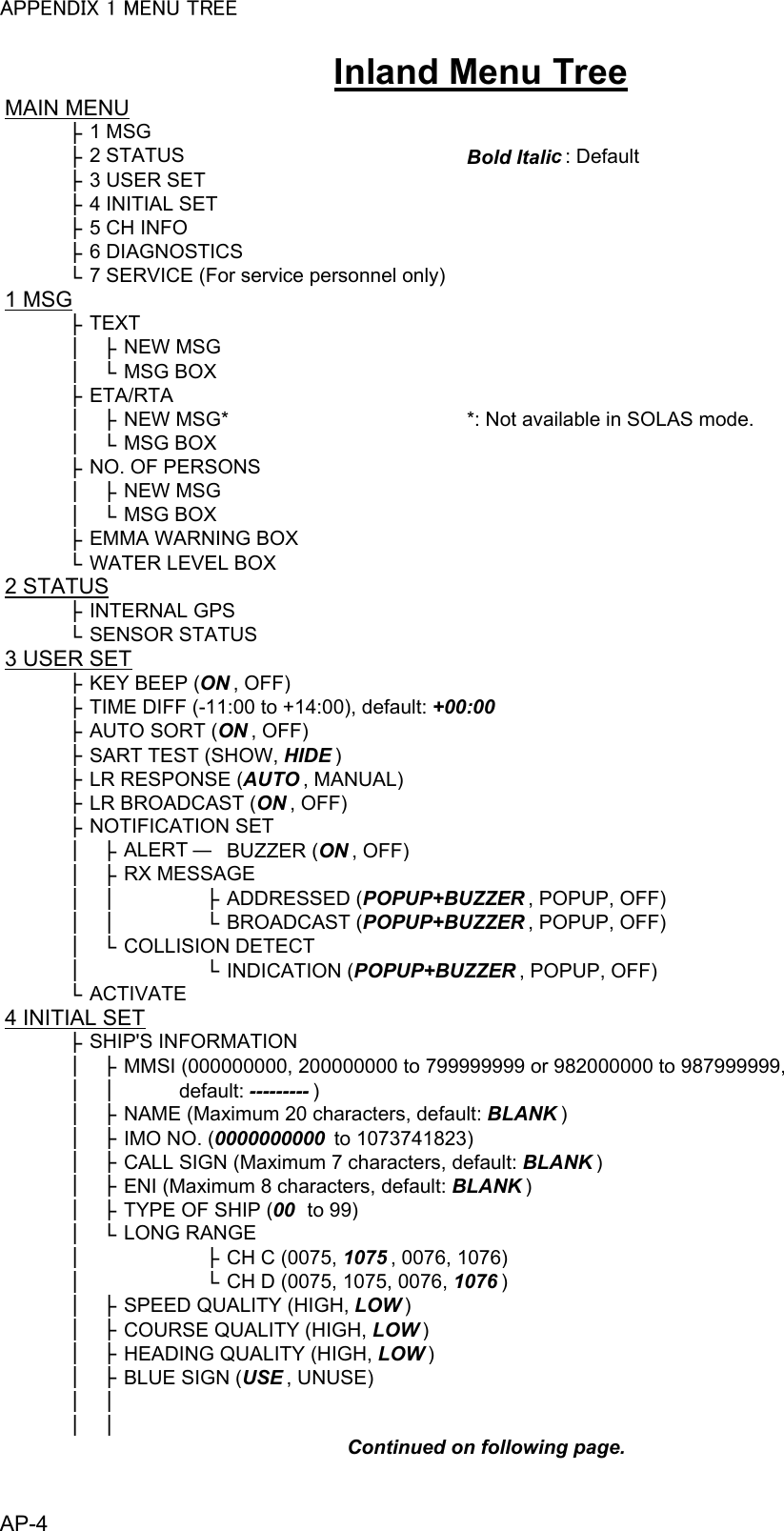
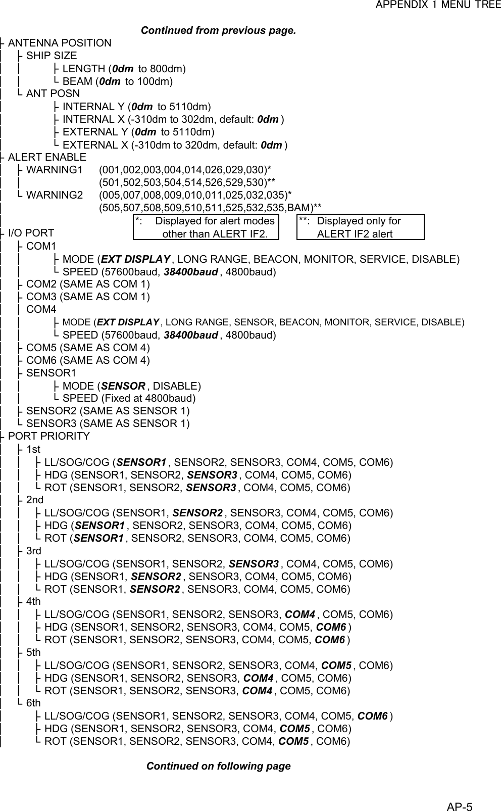
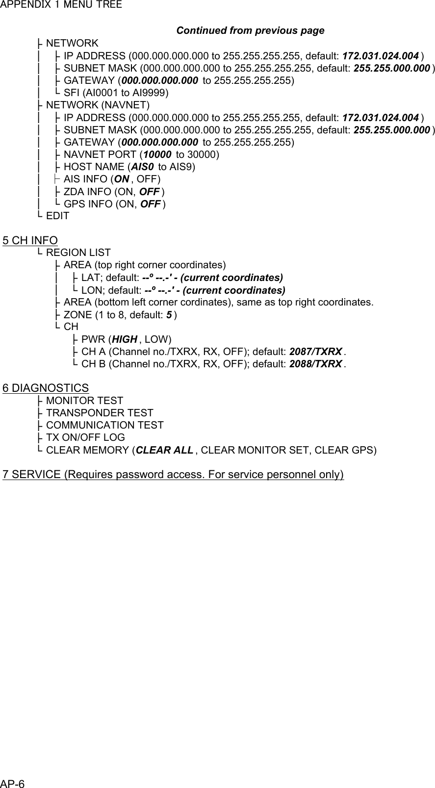
Furuno USA 9ZWFA170 Automatic Identification Systems User Manual OME 44900 A
Furuno USA Inc Automatic Identification Systems OME 44900 A
UserManual.wiki
>
Furuno USA
>
9ZWFA170 User Manual
>
User Manual II
Contents
1.
Installation Manual
2.
Installation Manual II
3.
User Manual
4.
User Manual II
User Manual II
Navigation menu
Upload a User Manual
Namespaces
Wiki Guide
HTML
PDF
Info
Views
User Manual
Discussion / Help
Navigation
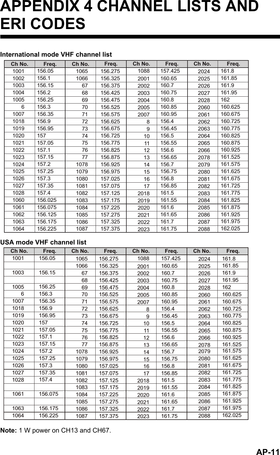
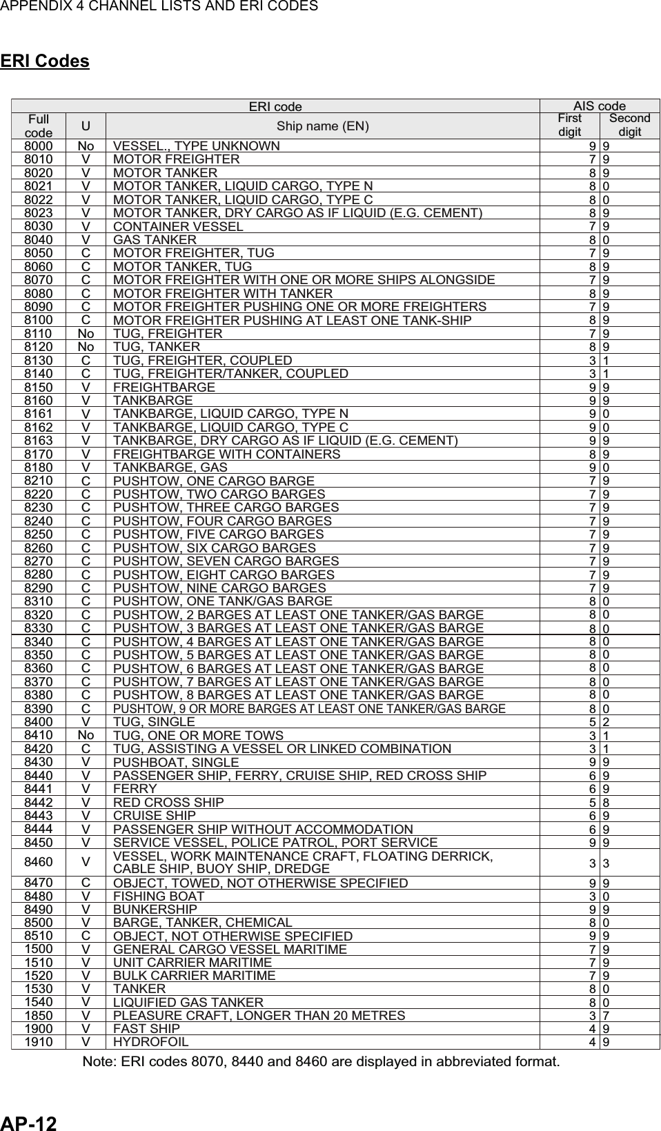
![2. INLAND AIS OPERATION2-612. Select [BLUE CONES], then press the ENT/ACK key. The pop up window shown below appears.Depending on the cargo, up to four “cones” have to be shown on the mast, in day-light with cones and nighttime with blue lights. The greater the number of the cones the more hazardous the cargo.• Select [NO. OF CONES 0] if your ship is not carrying hazardous cargo. • Select [B-FLAG] if your ship carries explosives or hazardous cargo that ex-ceeds the hazard level expressed with cones. • Select [UNKNOWN] if you are unsure of cargo type.13. Set [BLUE CONES] as necessary, then press the ENT/ACK key.14. Select [UN/LOADED], then press the ENT/ACK key. The pop up window shown to the right appears.15. Select [LOADED] for vessel loaded with cargo, [UNLOAD-ED] for vessel with no cargo, or [- - -] if you are unsure of the loading status.16. Select [CREW] is now selected, then press the ENT/ACK key.17. Enter number of crew (0-254) then press the ENT/ACK key.18. Select [PASSENGER], then press the ENT/ACK key.19. Enter number of passengers (0-8190) then press the ENT/ACK key.20. Select [PERSONNEL], then press the ENT/ACK key.21. Enter number of shipboard personnel (persons other than passengers and crew, 0-254) then press the ENT/ACK key.Note: Crew, passenger and shipboard personnel are sent in RFM55 messages.22. [NO. OF PERSONS] is selected; press the ENT/ACK key.23. Enter the total number of persons (sum of crew, passengers and shipboard per-sonnel) on-board then press the ENT/ACK key.Note: If the value entered for [CREW], [PASSENGER], [PERSONNEL] or [NO. OF PERSONS] exceeds the maximum setting listed in the steps above, the value appears as maximum for that item.BLUE CONESUNKNOWNNO . OF CONES 1NO . OF CONES 2NO . OF CONES 3B-FLAGNO . OF CONES 0UN/LOADEDLOADEDUNLOADED](https://usermanual.wiki/Furuno-USA/9ZWFA170.User-Manual-II/User-Guide-2884868-Page-1.png)
![2. INLAND AIS OPERATION2-724. Press to display the [SCALE] tab.25. Referring to the table below, input the length and beam of your vessel and the con-voy vessel.Press the arrow keys to move the selection cursor and highlight the item you wish to edit, then press the ENT/ACK key. A numerical input pop up window appears for the selected item.26. Select [DRAUGHT], then press the ENT/ACK key to display the [DRAUGHT] set-ting pop up window. The setting range is [0] cm to [2000] cm.27. Input the draught, then press the ENT/ACK key.28. Press the DISP key to close the menu.Menu item Description[EA] Length of convoy vessel A. Setting range [0] to [6800] dm.[EB] Length of convoy vessel B. Setting range [0] to [6800] dm.[EC] Beam of convoy vessel A. Setting range [0] to [400] dm.[ED] Beam of convoy vessel B. Setting range [0] to [400] dm.[LS] Own ship length. (Display only, not available for input.)[BS] Own ship beam. (Display only, not available for input.)[LC] Shows the total length of the convoy. (Display only, not available for input.)[BC] Shows the total beam of the convoy. (Display only, not available for input.)NAV STATUS: TAB: SELECT: CURSORENTVOYAGEDRAUGHTSHIP’S INFO SCALEEA:[CONVOY EXTENSION]0000dmEBLSLC:0000dm:0000cm0dm0dm0dm0dmEDBSBC:0000dmEC:0000dm120dmEDBS:0000dmEC:0000dmEA:0000dmEBLS:0000dm0dmConvoy layoutOwn vessel and convoy vessel lengthsOwn vessel and convoy vessel beamsOwn ship draught0000[0 , 2000 ]DRAUGHT](https://usermanual.wiki/Furuno-USA/9ZWFA170.User-Manual-II/User-Guide-2884868-Page-2.png)
![2. INLAND AIS OPERATION2-82.4 Static DataThe [OWN INFORMATION] display shows your ship’s data across four tabs. The in-formation displayed is shown in the figure below. This data should be checked once per voyage or once per month whichever is shorter. Data may be changed only on the authority of the master.The Officer of the Watch should periodically check position, SOG and sensor informa-tion for quality.Note: The [TYPE OF SHIP] indication on the [IDENTITY] tab changes to display the ERI code when INLAND mode is active.Update rate of dynamic ship informationShip’s dynamic conditions and nominal reporting intervalShip’s dynamic conditions Nominal reporting intervalShip at anchor or moored or aground or not under command and not moving faster than 3 kn3 minutesShip at anchor or moored or aground or not under command and moving faster than 3 kn10 secondsShip operating in SOLAS mode, moving 0-14 kn 10 secondsShip operating in SOLAS mode, moving 0-14 kn speed and changing course3 1/3 secondsShip operating in SOLAS mode, moving 14-23 kn 6 secondsShip operating in SOLAS mode, moving 14-23 kn and changing course2 secondsShip operating in SOLAS mode, moving faster than 23 kn2 secondsShip operating in SOLAS mode, moving faster than 23 kn and changing course2 secondsShip operating in inland waterway mode Assigned between 2 seconds and 10 minutesOWN INFORMATION: TAB : NEXTDISPSENSOR VOYAGE IDENTITY SCALEUTC12/NOV/2014 17 :20 :0034 º 44 .5000 ´N130 .0º135 .0º135 º 21.3000 ´E708 . 7 º/min ( )10 .0 knHIGHUNUSEDPOSN PARAIMHDGCOGROTSOGOWN INFORMATION: TAB : NEXTDISPSENSOR VOYAGE IDENTITY SCALENAV STATUSDESTINATIONETA(UTC)NO. OF PERSONSPERSONNELPASSENGERBLUE SIGN YESNO. OF CONES 1UNLOADEDBLUE CONESUN/LOADEDCREWPWR-DRIVEN VESSEL PUSHING AHEAD OR TOWING ALONGSIDEKOBE10 /MAY 10:5112OWN INFORMATION: TAB : NEXTDISPSENSOR VOYAGE IDENTITY SCALEMMSINAMEIMO NO.CALL SIGNTYPE OF SHIPWIGARRYING DG, HS, OR, MP(OS)24@SEVEN@ENI@EIGHT@FURUNOMARU29740917190123456789SENSOR tab VOYAGE tabIDENTITY tabSCALE tabPress ► or ◄ to cycle through the tabs.25581912558191OWN INFORMATION: TAB : NEXTDISPSENSOR VOYAGE IDENTITY SCALE[CONVOY EXTENSION][ANT POSN]EA500dm500dm1000dm400dm,600dm,250dm,250dm200dm,800dm,400dm,100dm0cm2000dm500dm250dm250dm1000dmEBLSINTEXTDRAUGHTLCECECBSBCA, B, C, D2112EXTERNALDGPS2](https://usermanual.wiki/Furuno-USA/9ZWFA170.User-Manual-II/User-Guide-2884868-Page-3.png)
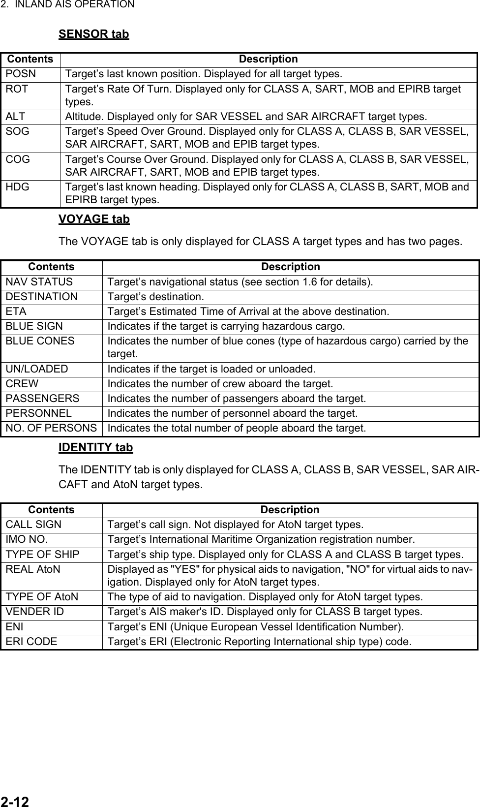
![2. INLAND AIS OPERATION2-92.5 Target List and Dangerous Target List2.5.1 Target listThe [TARGET LIST] can store up to 2048 AIS targets and AIS-SARTs being detected by the FA-170, in the order which they are detected. The list can be sorted in range order, from closest to farthest.1. Press the DISP key until the [TARGET LIST] or [DANGEROUS LIST] appears. Note: The last views list ([DANGEROUS LIST] or [TARGET LIST]) is displayed.Targets are displayed in groups of 100, however only eight targets are displayed on the screen at any time. The following operations are used in the TARGET LIST.The [NAME/MMSI/TYPE] column of the [TARGET LIST] displays the target ves-sel’s type in the following formats:For CLASS A/CLASS B/AtoN type targetsWhere the vessel name is available, the name is displayed. Where no name data is available, the MMSI is displayed.Operation DescriptionPress or . Scroll up or down the list of targets. The selected target is highlighted.Press or . Move to the next group of targets (next 8 targets).Select [NEXT 100 TAR-GETS], then press the ENT/ACK key.Move to the next page of the target list (next 100 targets).Note: Displayed only if more than 100 targets are detect-ed.Select [PREVIOUS 100 TARGETS], then press the ENT/ACK key.Move to the previous page of the target list (last 100 tar-gets).Note: Displayed only if more than 100 targets are detect-ed.Select a target, then press the ENT/ACK key.Display the selected target’s details. See section 2.5.3 for details.TARGET LIST 12:32:0181-88(334): CURSOR: FUNCENT: PAGE : NEXTDISPNAME/MMSI/TYPE RNG[km] BRG[ º ] AGE[ ‘ ]BAASARBSAMPLE SHIP 003 3 .5 100.0 0SAMPLE SHIP 004 3 .6 110.0SAMPLE SHIP 005 3 .7 120.0 0SAMPLE SHIP 006 3 .8 130.0 0SAMPLE SHIP 007 3 .9 140.0 0SAMPLE SHIP 008 3 .1 150.0 0SAMPLE SHIP 002 3 .4 090.0 0SAMPLE SHIP 002 3 .3 080.0 0NAME/MMSI/TYPE: Target’s MMSI, name or type is displayed. Where name data is available, the vessel name is displayed.RNG[km]: Range from OS to target.BRG[ º ]: Bearing to target.AGE[ ‘ ]: Time (in minutes) since the target data was last updated.Target type symbols.See Appendix 5 of the operator’s manual for a full list of AIS symbols and their meanings.Selected target is highlighted.Time at which the list was last sorted.Currently displayed target group. Total detected targets is displayed in brackets.](https://usermanual.wiki/Furuno-USA/9ZWFA170.User-Manual-II/User-Guide-2884868-Page-4.png)
![2. INLAND AIS OPERATION2-10For SAR(VESSEL/AIRCRAFT)/SART/MOB/EPIRB type targetsNote 1: If there is no data for the target selected, the fields are displayed as "=NO TARGET=".Note 2: Targets are automatically sorted in range order (closest to furthest) when no key is operated for 30 seconds. Target order is then updated every five sec-onds.Active AIS-SARTs take priority and are displayed at the top of the list.Note 3: When [AUTO SORT] on the [USER SET] menu is [OFF], the range and bearing to a target are updated. However, target order is not updated. To manu-ally sort targets, see step 2.Note 4: To select a target on the plotter display, press or to select the target then press the ENT/ACK key. Press to cycle through targets from nearest to furthest; to cycle through targets from furthest to nearest.2. To view target data, or to sort the target list, select the desired target, then press the ENT/ACK key. The target list options pop up window appears.• [SORT (NORMAL)]: Press to display and sort the [TARGET LIST] into range order. The closest target is displayed at the top of the list.• [SORT (DANGER)]: Press to display and sort the [DANGEROUS TARGET LIST] in range order. The closest target is displayed at the top of the list.• [VIEW DETAIL]: Press the ENT/ACK key to open the [TARGET DETAIL] screen.• [NEW MSG]: Press to open the text input window to create an AIS message to the selected target.• [NAME REQUEST]: Press to send a name request to the target vessel’s AIS.Note: Name requests cannot be sent to the same target within a short period, regardless of target. If you have requested the name of a target too soon after the last request, or the target is out of range, or the target has set their AIS to RX only mode, the pop up message "CANNOT REQUEST NAME" is displayed. Wait a short while before requesting the name again.3. Press the DISP key to close the menu.TYPE Display formatSAR vessel "SAR/VESSEL"SAR aircraft "SAR/AIRCRAFT"SART Active "SART ACTIVE"SART Test "SART TEST"MOB Active "MOB ACTIVE"MOB Test "MOB TEST"EPIRB Active "EPIRB ACTIVE"EPIRB Test "EPIRB TEST"AIS Base station "BS: (station’s MMSI/name)"FUNCTIONNEW MSGVIEW DETAIL SORT(DANGER)SORT(NORMAL)NAME REQUESTENT](https://usermanual.wiki/Furuno-USA/9ZWFA170.User-Manual-II/User-Guide-2884868-Page-5.png)
![2. INLAND AIS OPERATION2-112.5.2 Dangerous (target) listDangerous targets are targets which are calculated to be on a collision course with your vessel. When a dangerous target is detected, the target and its available details can be viewed in the [DANGEROUS TARGET LIST].The operations available from the [DANGEOUS TARGET LIST] are the same as the [TARGET LIST] operations. See section 2.5.1 and section 2.5.3 for details.Note: When no dangerous targets are detected, the list shows the message "= NO TARGET =".2.5.3 How to interpret the [TARGET DETAIL] screenThe [TARGET DETAIL] screen shows available detailed information about the select-ed target.Lost and dangerous targets have the appropriate icon displayed at the top right, as indicated in the lost target example below.There are five tabs available for viewing; [SENSOR], [VOYAGE], [IDENTITY], [SCALE] and [QUALITY]. Press or to change the tab currently displayed.The selected target’s bearing ([BRG]), range ([RNG]), [MMSI] and [NAME] are dis-played at the top of the screen regardless of the selected tab. For lost or dangerous targets, the appropriate icon is displayed at the top right of the screen.The information displayed on each tab varies, depending on the type of target select-ed.The tables on the following pages list each tab’s contents, along with a brief descrip-tion.DANGEROUS LIST12:32:019-16 (108): CURSOR: FUNCENT: PAGE : NEXTDISPSAMPLE SHIP 003 3 .5 100.0 0SAMPLE SHIP 004 3 .6 110.0SAMPLE SHIP 005 3 .7 120.0 0SAMPLE SHIP 006 3 .8 130.0 0SAMPLE SHIP 007 3 .9 140.0 0SAMPLE SHIP 008 3 .1 150.0 0SAMPLE SHIP 002 3 .4 090.0 0SAMPLE SHIP 002 3 .3 080.0 0NAME/MMSI/TYPE RNG[km] BRG[ ° ] AGE[ ‘ ]BAASARBTarget type symbols. See Appendix 5 for a full list of AIS symbols and their meanings.NAME/MMSI/TYPE: Target’s MMSI, name or type is displayed. Where name data is available, the vessel name is displayed.RNG[km]: Range from OS to target.BRG[ º ]: Bearing to target.AGE[ ‘ ]: Time (in minutes) since the target data was last updated.Selected target is highlighted.Time at which the list was last sorted.TARGET DETAIL: TAB: TARGET : BACKMENUSENSOR VOYAGE IDENTITY SCALE QUALITYCLASS AFURUNOMARUTYPE34 º 44 .5000 ´N130 .0º135 .0º135 º 21.3000 ´E108 . 7 º/min ( )10 .0 km/hPOSNHDGCOGROTSOG225.4º3.02NMBRGRNG 201503030NAMEMMSILOSTAThe LOST icon is displayed for lost targets.The DANGER icon is displayed for dangerous targets.When data input to the FA-170 is interrupted or stopped, indications for all tabs appear as “----”.](https://usermanual.wiki/Furuno-USA/9ZWFA170.User-Manual-II/User-Guide-2884868-Page-6.png)
![2. INLAND AIS OPERATION2-142.6 Inland AIS Specific MessagingAll sent and received messages are stored in their respective message box. Refer to the appropriate section below for how to view messages once they are sent or re-ceived.2.6.1 How to send a text message1. Press the MENU/ESC key to open the menu.2. Select [MSG], then press the ENT/ACK key.3. [TEXT] is selected, press the ENT/ACK key.4. Select [NEW MSG], then press the ENT/ACK key.5. [MSG TYPE]is selected, press the ENT/ACK key to change the type of message you wish to send. The options pop up shown below appears.6. Select the appropriate message type, then press the ENT/ACK key.For broadcast messages, skip to step 9.7. Select [TO], then press the ENT/ACK key. A numerical settings pop up appears.8. Input the MMSI of the ship you wish to send this message to, then press the ENT/ACK key to close the pop up. See section 1.5 for how to input data.MSGTEXTETA/RTANO. OF PERSONSWATER LEVEL BOXEMMA WARNING BOX12345TEXTNEW MSGMSG BOX12NEW MSG TEXT( )MSG TYPE<SEND MSG>: CURSOR: SELECTADDRESSED: BACKENTMENU:TO 000000000:CH ALTERNATE:RETRY 3:TEXT( 0 / 85 )Use the software keyboard to enter the message here.:MSG TYPEBROADCASTADDRESSEDMessage to all vessels.Message to specified vessel only.](https://usermanual.wiki/Furuno-USA/9ZWFA170.User-Manual-II/User-Guide-2884868-Page-9.png)
![2. INLAND AIS OPERATION2-159. Select [CH] (Channel), then press the ENT/ACK key. The channel select options pop up appears.10. Select the appropriate option, then press the ENT/ACK key.For broadcast messages, skip to step 13.11. Select [RETRY], then press the ENT/ACK key. The retry attempts setting pop up appears.12. Press to increase the retry attempts, to decrease the retry attempts. The maximum setting for retries is 3. Press the ENT/ACK key to apply the setting and close the pop up.13. Press to highlight the message text, then press the ENT/ACK to display the software keyboard.14. Input the new message text, referring to section 1.5.4. The maximum number of characters allowed is as follows:• BROADCAST: 90 characters.• ADDRESSED: 85 characters.15. Press or to highlight [<SEND MSG>] at the top right of the screen, then press the ENT/ACK key. A confirmation pop up appears.16. Select [YES] to send the message or [NO] to cancel the message, then press the ENT/ACK key.CHBOTH A & BONLY AONLY BALTERNATESends the same message to both channel A and channel B.Sends the message to channel A only.Sends the message to channel B only.Sends messages on alternating channels. In other words, if the last message sent on channel A, the next message is sent on channel B.](https://usermanual.wiki/Furuno-USA/9ZWFA170.User-Manual-II/User-Guide-2884868-Page-10.png)
![2. INLAND AIS OPERATION2-162.6.2 How to view a sent text message1. Press the MENU/ESC key to open the menu.2. Select [MSG], then press the ENT/ACK key.3. Select [TEXT], then press the ENT/ACK key.4. Select [MSG BOX], then press the ENT/ACK key. The message box appears. 5. Select the message you wish to view, then press the ENT/ACK key. The message options pop up window shown below appears.Select [VIEW DETAIL], then press the ENT/ACK key to display the received mes-sage’s contents. The figure above shows an example of a received message.Select [NEW MSG], then press the ENT/ACK key to send a message back to this message’s sender.6. Press or to view other messages, press or to switch between viewing an [INBOX] message and an [OUTBOX] message.7. Press the DISP key to close the menu.2.6.3 ETA and RTA messagesThe purpose of an ETA message is to apply for a time slot at a lock, bridge or terminal. (Hereafter “lock” refers to lock, bridge or terminal.) The message contains your ship's ETA at the lock, air draught, the number of assisting tugboats required and the partic-ulars of the lock (country code, location code, etc.).Upon receipt of your ETA message, the lock authority responds with an RTA (Re-quested Time of Arrival) message, usually within 15 minutes of receipt of the ETA message. The RTA message contains lock operational status, requested time of ar-rival and the particulars of the lock (country code, location code, etc.).MSGTEXTETA/RTANO. OF PERSONSWATER LEVEL BOXEMMA WARNING BOX12345MSG BOX ( TEXT )INBOX: 12OUTBOX: 10TIME [UTC]30 /MAY 18 : 25BROADCASTBROADCASTTITANICNAUTILUSBROADCASTBROADCASTMUSASHIMARU29 /MAY 16 :0528 /MAY 16 :1527 /MAY 17 :2026 /MAY 17 :2025 /MAY 17 :2024 /MAY 17 :20TO 01 / 10: CURSOR: FUNCENT: TAB: BACKMENUIndication MeaningThis message was sent successfully.This message was not sent.Waiting for recipient to acknowledged this message.Broadcast messageAddressed messageNOACKNOACKOKOKOKOKNGNGNO ACKNGFUNCTIONVIEW DETAILNEW MSGMENUINBOX MSG DETAIL ( TEXT )MSG TYPE ADDRESSED28 / MAY 16 : 15987654321 / ENTERPRISEKLINGONS ON STBD BOW.TIME [UTC]TOTEXT( 21): BACK: BOX: MESSAGE](https://usermanual.wiki/Furuno-USA/9ZWFA170.User-Manual-II/User-Guide-2884868-Page-11.png)
![2. INLAND AIS OPERATION2-17How to send an ETA message1. Press the MENU/ESC key to open the menu.2. Select [MSG], then press the ENT/ACK key.3. Select [ETA/RTA], then press the ENT/ACK key.4. Select [NEW MSG], then press the ENT/ACK key.5. [TO] is selected. Press the ENT/ACK key. to display the MMSI settings pop up window.6. Enter the MMSI of the lock/bridge/terminal you want to pass through then press the ENT/ACK key.7. Select [CH], then press the ENT/ACK key.8. Select the channel over which to send the message then press the ENT/ACK key.9. Select [RETRY], then press the ENT/ACK key. The retry attempts setting pop up appears.10. Press to increase the retry attempts, to decrease the retry attempts. The maximum setting for retries is 3. Press the ENT/ACK key to apply the setting and close the pop up.11. Select [DESTINATION] then press the ENT/ACK key. The [INLAND DESTINA-TION LIST] appears.ETA/RTANEW MSGMSG BOX12The [NEW MSG] option in the [ETA/RTA] pop up window is not available for selection in [SOLAS] mode.NEW MSG (ETA)<SEND MSG>: CURSOR: SELECT000000000: BACKENTMENU:TOCHRETRYDESTINATIONCOUNTRY CODEFAIRWAY NO.FAIRWAY HECTETA[UTC]AIR DRAUGHTNO. OF TUGBOATS:ALTERNATE:::::3DEDELOCATION CODETRI11111TERMINAL CODE012345678912/MAY0 .0cm012:32TRI012341111156789CHBOTH A & BONLY AONLY BALTERNATESends the same message to both channel A and channel B.Sends the message to channel A only.Sends the message to channel B only.Sends messages on alternating channels. In other words, if the last message sent on channel A, the next message is sent on channel B.INLAND DESTINATION LIST<EDIT>DE TRI 01234 11111 5678900000 0000000000 0000000000 0000000000 0000000000 0000000000 0000000000 000000706050403020108INLAND DESTINATION<COPY>CURSOREXEC FUNCBACK<PASTE><CUT><SET>01 / 20ENTMENU](https://usermanual.wiki/Furuno-USA/9ZWFA170.User-Manual-II/User-Guide-2884868-Page-12.png)
![2. INLAND AIS OPERATION2-1812. Referring to section 2.3, select or edit an existing destination or create a new des-tination. The figure below shows an example destination and the edit pop up win-dows.When setting an destination for the [INLAND DESTINATION LIST] the following details are required.• Country code: The UN country code of your destination. (Referring to ISO 3166.)• Three letter location code.• Fairway number and hectometer.• Terminal code.Note: For location codes, fairway numbers (and hectometers) and terminal codes, refer to the ERI (Electronic Reporting International) Guide Part IV Annex 2 for ex-amples.13. Input or edit the destination as appropriate, then press the ENT/ACK key.Press to increase the value (or the next character, in alphabetical order), press decrease the value (or the previous character, in alphabetical order). Press to move the selection cursor to the right, to move the cursor to the left.14. Select [<SET>], then press the ENT/ACK key.15. Select [ETA (UTC)], then press the ENT/ACK key. The settings pop up window shown below appears.16. Select [AIR DRAUGHT], then press the ENT/ACK key.17. Enter your ship's air draught then press the ENT/ACK key. (Air draught is the ver-tical distance measured from the ship's waterline to the highest point on the ship.)18. Select [NO. OF TUGBOATS], then press the ENT/ACK key.19. Enter the no. of assisting tugboats (0-6) your ship requires then press the ENT/ACK key. Enter [0] for none.20. Press or to highlight [<SEND MSG>] at the top right of the screen, then press the ENT/ACK key. The system will now attempt to send the message.00000 0000005INLAND DESTINATION LIST<EDIT>DE TRI 01234 11111 5678904030201INLAND DESTINATION<COPY>CURSOREXEC FUNCBACK<PASTE><CUT><SET>01 / 20ENTMENU000000000005INLAND DESTINATION LIST<EDIT>DETRI01234111115678904030201INLAND DESTINATION<COPY>CURSOREXECFUNCBACK<PASTE><CUT><SET>01 / 20ENTMENUTRI012341111156789DECOUNTRY CODEFAIRWAY NO.FAIRWAY HECTLOCATION CODETERMINAL CODETRI012341111156789INLAND DESTINATIONDEEditing pop up window.Currently selected destination’s details.12 / 10 12:32ETA (UTC)ETA monthETA day ETA timein 24hr format](https://usermanual.wiki/Furuno-USA/9ZWFA170.User-Manual-II/User-Guide-2884868-Page-13.png)
![2. INLAND AIS OPERATION2-19How to view sent ETA messages and received RTA messagesA lock authority responds to an ETA message with an RTA message. An RTA mes-sage contains the date and time the lock authority requests that your ship arrive to the lock, lock status and the particulars of the lock (country code, location code, etc.)When an RTA message is received, a pop up showing the message "RTA MESSAGE RECEIVED." appears. The pop up also shows the sender’s MMSI ID, or the sender’s name it if is included in the message.To view past messages, do the following:1. Press the MENU/ESC key to open the menu.2. Select [MSG], then press the ENT/ACK key.3. Select [ETA/RTA], then press the ENT/ACK key.4. Select [MSG BOX], then press the ENT/ACK key. The message box appears.Press or to switch between the [OUTBOX(ETA)] and [INBOX(RTA)] tabs.5. Select the message you wish to view, then press the ENT/ACK key. The message options pop up window shown below appears.Select [VIEW DETAIL], then press the ENT/ACK key to display the received mes-sage’s contents. The figure above shows an example of a received message.Select [NEW MSG], then press the ENT/ACK key to send a message back to this message’s sender.6. Press or to view other messages, press or to switch between viewing an [INBOX] message and an [OUTBOX] message.7. Press the DISP key to close the menu.MSG BOX (ETA/RTA) INBOX(RTA): 12OUTBOX(ETA): 10TIME [UTC]30 /MAY 17 : 20 BROADCASTBROADCASTENTERPRISEBROADCASTNEPTUNEBROADCASTNAUTILUS29 /MAY 16 :0528 /MAY 16 :1527 /MAY 17 :2026 /MAY 17 :2025 /MAY 17 :2024 /MAY 17 :20FROM 01 / 10: CURSOR: FUNCENT: TAB: BACKMENUIndication MeaningThis message has been viewed.This message is unviewed.Broadcast messageAddressed messageINBOX MSG DETAIL (RTA): MESSAGE : BOX: BACKMENUMSG TYPE RTA30 / AUG 18 : 30FROMTIME [UTC]DESTINATIONCOUNTRY CODEFAIRWAY NO.FAIRWAY HECTETA[UTC]STATUSMMSI / Sender’s name appears hereDEDELOCATION CODETRI11111TERMINAL CODE012345678912/MAYLIMITED OPERATION12:32TRI012341111156789FUNCTIONVIEW DETAILNEW MSG](https://usermanual.wiki/Furuno-USA/9ZWFA170.User-Manual-II/User-Guide-2884868-Page-14.png)
![2. INLAND AIS OPERATION2-202.6.4 No. of persons messageA number of persons message informs authorities or ships how many persons (pas-sengers, crew, shipboard personnel) you have on board your ship. Send this message on request or in case of an event.1. Press the MENU/ESC key to open the menu.2. Select [MSG] then press the ENT/ACK key.3. Select [NO. OF PERSONS] then press the ENT/ACK key.4. Select [NEW MSG], then press the ENT/ACK key.5. [MSG TYPE] is selected; press the ENT/ACK key.6. Select the appropriate message type, then press the ENT/ACK key.IFM messages require the total number of people on board.RFM messages require a breakdown of the total people on board (No. of crew, passengers and personnel).7. Select [CH], then press the ENT/ACK key.8. Select the channel to use to send the message then press the ENT/ACK key.9. Select [RETRY], then press the ENT/ACK key. The retry attempts setting pop up appears.10. Press to increase the retry attempts, to decrease the retry attempts. The maximum setting for retries is 3. Press the ENT/ACK key to apply the setting and close the pop up.11. Select and enter the total number for [NO. OF PERSONS] (IFM message) or [CREW], [PASSENGER] and [PERSONNEL] (RFM message), then press the ENT/ACK key.12. Press or to highlight [<SEND MSG>] at the top right of the screen, then press the ENT/ACK key. The system will now attempt to send the message.NO. OF PERSONSNEW MSGMSG BOX12NEW MSG (PERSONS)MSG TYPE<SEND MSG>: CURSOR: SELECTIFM / ADDRESSED: BACKENTMENU:TO 000000000:CH ALTERNATE:RETRY 3:NO. OF PERSONS : 0MSG TYPEIFM / BROADCASTIFM / ADDRESSEDRFM / BROADCASTRFM / ADDRESSEDIFM message to all vessels on the same channel.IFM message to specified vessel only.RFM message to all vessels on the same channel.RFM message to specified vessel only.CHBOTH A & BONLY AONLY BALTERNATESends the same message to both channel A and channel B.Sends the message to channel A only.Sends the message to channel B only.Sends messages on alternating channels. In other words, if the last message sent on channel A, the next message is sent on channel B.](https://usermanual.wiki/Furuno-USA/9ZWFA170.User-Manual-II/User-Guide-2884868-Page-15.png)
![2. INLAND AIS OPERATION2-212.6.5 EMMA warning messageEMMA (European Multiservice Meteorological Awareness) warnings are sent by base stations to skippers to inform them of special meteorological situations. EMMA does not provide continuous weather information, but only warnings of wind, rain, snow and ice, thunderstorm, fog, extreme temperatures (low and high), flood, fire in the forest. These messages are additional to the Notices to Skippers warnings.When you receive an EMMA warning, the "EMMA WARNING RECEIVED" pop up window appears and shows the MMSI or name of the sending agency. To see the con-tents of the message, do the following:1. Press the MENU/ESC key to open the menu.2. Select [MSG] then press the ENT/ACK key.3. Select [EMMA WARNING BOX] then press the ENT/ACK key.4. Select a message then press the ENT/ACK key.The EMMA warning message looks something like example below. To view the other messages, press or .5. Press the MENU/ESC key to close the message.The information includes the following:• Start time of validity• End time of validity• Fairway section start and end co-ordinates• Type of weather warning• Minimum value• Maximum value• Classification of warning• Wind directionItem DescriptionTYPE [FIRE IN THE FORESTS], [FOG], [FLOOD], [HIGH TEMPERATURE], [LOW TEMPERATURE], [RAIN], [SNOW AND ICE], [THUNDER-STORM], [WIND]Units of measurement are as follows:• km/h (wind)• °C (temperature)• cm/h (snow)• l/m2h (rain)• m (visibility distance in fog)MIN, MAX VALUE The minimum and maximum value of respective item over one hour. For ex-ample, if the minimum and maximum values for snow and ice are 1 and 4 re-spectively, this means that 1-4 cm of snow or ice has fallen in one hour.The indication range is -254 to +254, or "- - - -" in case where a value is not reported, for example, fire in the forests and flood.CLASS Weather classification: [SLIGHT], [MEDIUM], [STRONG/HEAVY] or "- - - - - - - -" (unknown)WIND DIRECTION [NORTH], [NORTH EAST], [EAST], [SOUTH EAST], [SOUTH], [SOUTH WEST], [WEST], [NORTH WEST] or "- - - -" (Where no wind data is avail-able.)EMMA WARNING MSG DETAILTIME [UTC]30 /SEP 17: 2026 /JAN 15: 00 ~ 26 / JAN 18 :00 34 º25 .0000 ‘N 34 º35 .0000 ‘N134 º25 .0000 ‘E 134 º35 .0000 ‘E123456789 / NAUTILUSTERM [UTC]AREATYPE WINDMEDIUMNORTH EAST36 ~ 50 [km/h]CLASSWIND DIRECTIONVALUE (MIN~MAX)FROM: MESSAGE: BACKMENU~Time and date the message was received.Time frame (from date/time to date/time) and area (coordinates) of the warning.Type of weather warning, class of warning and other details of the warning.](https://usermanual.wiki/Furuno-USA/9ZWFA170.User-Manual-II/User-Guide-2884868-Page-16.png)
![2. INLAND AIS OPERATION2-222.6.6 Water level messageThe water level message is sent by base stations to inform skippers about actual wa-ter levels in their area. It is additional short-term information to the water levels distrib-uted via Notices to Skippers. The message contains the country code (location), gauge ID and water level.When you receive a water level message, a pop up displays "WATER LEVEL MES-SAGE RECEIVED.".To see the contents of the message, do the following:1. Press the MENU key to open the menu.2. Select [MSG] then press the ENT/ACK key.3. Select [WATER LEVEL BOX] then press the ENT/ACK key.4. Select a message then press the ENT/ACK key.5. Press the MENU/ESC key to close the message.WATER LEVEL MSG DETAIL4 . 24m5 . 33m1 . 23m- 1 . 22mTIME [UTC]30 /SEP 17: 20123456789 / NAUTILUSFROMCOUNTRY CODE JPGAUGE ID0007001502552047WATER LEVEL: MESSAGE: BACKMENUNational unique gauge IDNational unique gauge IDNational unique gauge ID Positive or negative valuePositive or negative valuePositive or negative valueTIME[UTC]30 /SEP 17: 20123456789 / NAUTILUSFROMCOUNTRY CODEJPTime/date received, sender’s details and country code.Time/date received, sender’s details and country code.](https://usermanual.wiki/Furuno-USA/9ZWFA170.User-Manual-II/User-Guide-2884868-Page-17.png)
![2. INLAND AIS OPERATION2-232.7 Viewing Initial SettingsThe [INITIAL SET] menu, which is locked with a password to prevent accidental changes to the ship’s details, is where the installer enters ship’s MMSI, internal and external antenna positions, ship type, I/O port settings and network settings. You can view the settings on this menu as follows.1. Press the MENU/ESC to open the menu.2. Press the ENT/ACK key twice.3. Select item to view then press the ENT/ACK key.4. Press the DISP key to close the menu.SHIP’S INFORMATIONMMSI 234567891PERSEPHONE98765432100100000@SEVEN@NAMEIMO NO.CALL SIGNENICH C 0075CH D 0076[LONG RANGE]: BACKMENU24 (WIG)TYPE OF SHIPHIGHSPEED QUALITYCOURSE QUALITYHEADING QUALITYBLUE SIGN SWHIGHHIGHUSEANTENNA POSITION: BACKMENU120dm 60dm60dm80dmXY210[SHIP SIZE ] LENGTH BEAM[ANT POSN] Y X[ANT POSN] A , B C , DINTERNALEXTERNALINTERNAL60 , 6040 , 8030 , 3045 , 15EXTERNAL12120dm15dmALERT ENABLE: BACK: CURSORMENUWARNING1ENABLE001 014026030029005007009010008011025035032002003004DISABLEENABLEHILO001 :TX MALFUNCTIONDISABLEWARNING2: 8 : 0 : 0: 10PORTCOM138400baud38400baud38400baud38400baud38400baud38400baud4800baud4800baud4800baudCOM2COM3COM4COM5COM6SENSOR1SENSOR2SENSOR3 SENSORSENSORSENSOREXT DISPLAYEXT DISPLAYEXT DISPLAYEXT DISPLAYEXT DISPLAYLONG RANGEMODESPEEDI / O PORT: BACKMENULOCKSHIP’S INFORMATIONANTENNA POSITIONALERT ENABLEI / O PORTPORT PRIORITYNETWORKEDIT :INITIAL SET1234567PRIORITYLL /SOG / COGHDGROT2nd1st3rd4th5th6thSENSOR1SENSOR3 SENSOR3SENSOR1 SENSOR1SENSOR2 SENSOR2SENSOR2SENSOR3COM4 COM6COM4COM5COM6COM4COM5COM5COM6PORT PRIORITY: BACKMENU IP ADDRESS172 . 031 . 024 . 004255 . 255 . 000 . 000000 . 000 . 000 . 000SUBNET MASKGATEWAYAI0001SFINETWORK: BACKMENUNote: The availability of some functions depends on the equipment specifications of your vessel. Some items are not displayed unless the vessel is equipped accordingly.Password access is required to change these settings. Contact your local dealer to change the settings if required.Displayed as “NETWORK (NAVNET)” when the network type is set to [NAVNET].](https://usermanual.wiki/Furuno-USA/9ZWFA170.User-Manual-II/User-Guide-2884868-Page-18.png)
![2. INLAND AIS OPERATION2-242.8 Setting for Time DifferenceYou can set the time differences from UTC (Coordinated Universal Time) to show the local time.1. Press the MENU/ESC key to open the menu.2. Select [USER SET] then press the ENT/ACK key.3. Select [TIME DIFF], then press the ENT/ACK key. The settings pop up window is displayed. 4. Select the desired time difference then press the ENT/ACK key. You can change the value with or , the digit with or The setting range is -14:00 to +14:00.5. Press the DISP key to close the menu.Note: When a UTC time offset is set, the time display indication for messages and NAV STATUS screen is indicated as "LT" (Local Time). When there is no offset, the time display indication for messages and the NAV STATUS screen is indicated as "UTC" (Coordinated Universal Time).USER SETKEY BEEPAUTO SORTTIME DIFFONHIDEAUTO+00 : 00ONSART TESTLR RESPONSELR BROADCASTNOTIFICATION SETACTIVATE12345678ON+ 00:00[ -14 : 00 , 14 : 00 ]](https://usermanual.wiki/Furuno-USA/9ZWFA170.User-Manual-II/User-Guide-2884868-Page-19.png)
![3. MAINTENANCE, TROUBLESHOOTING3-23.2 Replacement of FuseThe transponder unit contains a 8A fuse which protects the equipment from overvolt-age, reverse polarity and equipment fault. If the power cannot be turned on, the fuse may be blown. Contact your local dealer for advice.3.3 TroubleshootingThe troubleshooting table below provides common symptoms of trouble and the means to rectify them. If you cannot restore normal operation, do not attempt to check inside the equipment. Refer any repair work to a qualified technician.Unit Fuse type Specification Code No.Transponder unit FA-1701 FGMB 125V 8 A PBF 12 to 24VDC 000-191-004Symptom RemedyPowerCannot turn on the power.• Check that the power cable between the transponder and monitor units for damage.• Check the power supply.Transmitting, receiving messagesCannot transmit or receiver.• Check that the VHF antenna cable is firmly fastened.• Check the VHF antenna for damage.• For TX messages, try a different TX channel. CLASS A: See section 1.9.1.INLAND: See section 2.6.1.Can transmit but message is sent to wrong party.Check that the[ MSG TYPE] is set to [ADDRESSED] and the MMSI entered at [TO] is correct.For CLASS-A, see section 1.9.1.For INLAND: See section 2.6.1.Position dataNo position data. • Check the GPS antenna for damage.• Check the GPS antenna cable and its connectors.WARNINGUse the proper fuse.Use of a wrong fuse can cause fire orresult in damage to the equipment.](https://usermanual.wiki/Furuno-USA/9ZWFA170.User-Manual-II/User-Guide-2884868-Page-21.png)
![3. MAINTENANCE, TROUBLESHOOTING3-33.4 DiagnosticsThe FA-170 provides diagnostic tests to check the monitor unit and transponder unit for proper operation.3.4.1 Monitor unit testThe monitor unit test shows program no., and checks the ROM, RAM, LCD and con-trols.1. Press the MENU/ESC key to open the main menu.2. Select [DIAGNOSTICS] then press the ENT/ACK key.3. [MONITOR TEST] is already selected; press the ENT/ACK key.a) The screen in the test displays the monitor unit’s program number and serial number. b) The ROM and RAM are checked. The results of the ROM/RAM check are shown as "OK" or "NG" (No Good). If "NG" appears, try the test again. If "NG" still appears, contact your dealer for advice.DIAGNOSTICSMONITOR TESTTRANSPONDER TESTCOMMUNICATION TESTTX ON/OFF LOGCLEAR MEMORY12345MONITOR TESTPROGRAM NO. 0550256-XX.XXXXXXXX“XX.XX” indicates software version number.OKOKROMRAM: BACKSERIAL NO.MENU](https://usermanual.wiki/Furuno-USA/9ZWFA170.User-Manual-II/User-Guide-2884868-Page-22.png)
![3. MAINTENANCE, TROUBLESHOOTING3-43.4.2 Transponder testThe transponder tests two aspects of the transponder: transponder memory and inter-nal GPS receiver.To run this test, do the following:1. Press the MENU/ESC key to open the main menu.2. Select [DIAGNOSTICS] then press the ENT/ACK key.3. Select [TRANSPONDER TEST] then press the ENT/ACK key.4. The transponder program number and serial number are displayed and the ROM and RAM are checked. The results of the ROM and RAM check are displayed as "OK" or "NG" (No Good). For any "NG", contact your dealer for advice.The GPS test results are displayed the format shown below.5. Press the MENU/ESC key to return to the [DIAGNOSTICS] sub-menu.OK: NormalNG: No Good - Appears along with reason for NG.• ROM ERROR• RAM ERROR• MEMORY ERROR• COM ERROR• ANTENNA ERRORTRANSPONDER TESTPROGRAM NO. 0550255-XX.XX1000-42xx-xxxOKOKOKSERIAL NO.ROMRAMGPS: BACKMENU](https://usermanual.wiki/Furuno-USA/9ZWFA170.User-Manual-II/User-Guide-2884868-Page-23.png)
![3. MAINTENANCE, TROUBLESHOOTING3-53.4.3 VHF communication testThe VHF communication test checks for proper transmission and reception over the VHF channel.1. Press the MENU/ESC key to open the main menu.2. Select [DIAGNOSTICS] then press the ENT/ACK key.3. Select [COMMUNICATION TEST] then press the ENT/ACK key.4. Input the required MMSI, referring to the list at the right of the screen. You can also select the test target from the list at the right of the screen using the arrow keys, then press the ENT/ACK key.5. Select [START] then press the ENT/ACK key.When the test is complete, the re-sults are displayed for both chan-nel A and B, along with a reason for test failure where applicable."OK": Normal"NG": No Good. Unable to com-municate with specified vessel’s (MMSI) channel.The result "NG" appears with a number explaining the failure. The number and meanings are listed in the table below.6. Press the MENU/ESC key to return to the [DIAGNOSTICS] sub-menu.Number Reason Measures1 No response. The message was not acknowledged by the test target.Change targets, then repeat the test.2 Own ship MMSI is not set. Refer to the installation manual for this equipment and input the MMSI.3 The FA-170 is set to “receive only” and cannot send a test message.Change the setting for [CH INFO] to [TX/RX AorB] from the [REGION LIST]. See section 1.10.2.Note: The system automatically transmits when the setting is changed to [TX/RX AorB].4 The FA-170 is in silent mode and cannot send a test message.Disable silent mode.5 Less than one minute interval be-tween messages sent.Wait for more than one minute, then repeat the test.6 Failed for an unknown reason. (Oth-er than those above.)There may be an obstacle (land mass, etc.) be-tween your vessel and the test vessel. Manually input a different test target MMSI then repeat the test.COMMUNICATION TEST: BACK: SELECTMENUENT< START >TEST TARGET [ 15NM-25NM TARGETS ]RNGMMSI15NM16NM17NM17NM19NM20NM20NM111111110222222220333333330444444440555555550666666660777777770= NO ENTRY =1:2:3:4:5:6:7:8::CH A RESULT - -- -CH B RESULT[ NG REASONS ]1=NO RESPONSE2=NO MMSI3=RECEIVE ONLY4=SILENT MODE5=OTHER000000000: CURSORSelect [START], then press the ENT/ACK key to begin the communications test.Available test targets list showing the MMSI of each target and range to target.The FA-170 automatically selects targets with a range of 15 NM to 25 NM for this list with CLASS A type targets listed above other types.COMMUNICATION TEST: BACK: SELECTMENUENT< STOP >TEST TARGET [ 15NM-25NM TARGETS ]RNGMMSI15NM16NM17NM17NM19NM20NM20NM111111110222222220333333330444444440555555550666666660777777770= NO ENTRY =1:2:3:4:5:6:7:8::CH A RESULTCH B RESULT[ NG REASONS ]1=NO RESPONSE2=NO MMSI3=RECEIVE ONLY4=SILENT MODE5=OTHER000000000: CURSOR](https://usermanual.wiki/Furuno-USA/9ZWFA170.User-Manual-II/User-Guide-2884868-Page-24.png)
![3. MAINTENANCE, TROUBLESHOOTING3-63.4.4 TX on/off logThe [TX ON/OFF LOG] shows the date and time at which transmissions were started or stopped. The time and date at which unit was turned off is also displayed.1. Press the MENU/ESC key to open the main menu.2. Select [DIAGNOSTICS] then press the ENT/ACK key.3. Select [TX ON/OFF LOG] then press the ENT/ACK key.The reasons which may be displayed are listed in the table below, along with their meaning.4. Press or to move the cursor and display other log entries.The cursor selects two lines, as shown in reverse video in the figure above. The contents of each log entry are:• Top line: Date and time at which transmission was turned off and reason trans-mission was turned off.Note: If transmission is turned off for more than 15 minutes, one of the reasons listed below is displayed.• Bottom line: Date and time at which transmission was turned on.5. Press the MENU/ESC key to return to the [DIAGNOSTICS] sub-menu.Reason MeaningPOWER OFF Transmission disabled due to unit power off.SILENT MODE Transmission disabled due to unit operating in SI-LENT mode.CH MANAGEMENT COMMAND Transmission disabled due to CH INFO receive mode.EQUIPMENT MALFUNCTION Transmission disabled due to equipment malfunc-tion.INVALID CONFIGURATION Transmission disabled due to invalid settings.Reason Meaning"POWER OFF" Transmission ceased as the power was turned off."SILENT MODE" Transmission ceased due to activation of [SI-LENT] mode."CH MANAGEMENT COMMAND" Transmission ceased due to current channel settings."EQUIPMENT MALFUNCTION" Transmission ceased due to equipment fault."INVALID CONFIGURATION" Transmission ceased due to invalid settings.TX ON/OFF LOG: CURSOR: BACKENT- - / - - - / - - - - - - : - - : - -30/APL/2015 8:35:00 29/APL/2015 8:35:00 29/APL/2015 17:20:00 28/APL/2015 17:20:00 27/APL/2015 17:20:00 CH MANAGEMENT COMMANDCH MANAGEMENT COMMANDCH MANAGEMENT COMMAND38/APL/2015 8:35:00 37/APL/2015 8:35:00 TX-OFF REASON008 / 020TIME [UTC]TX-ONEQUIPMENT MALFUNCTION](https://usermanual.wiki/Furuno-USA/9ZWFA170.User-Manual-II/User-Guide-2884868-Page-25.png)
![3. MAINTENANCE, TROUBLESHOOTING3-73.5 AlertsThe buzzer sounds for equipment errors and is accompanied by a flashing indication at the bottom of the screen. Press the ENT/ACK key to silence the buzzer and ac-knowledge the alert.If there are multiple alerts, each alert must be acknowledged individually.The indication at the bottom of the screen remains until the alert cause is removed or rectified.To see which alert(s) has been violated, display the [ALERT] log as shown in the pro-cedure below.1. Press the DISP key to show the [ALERT] log.2. Use or to select an alert. Each alert is displayed with the date and time at which it was generated. Where there is no date/time data available, the date/time indication appears as “- -/- - - - -:- -”.Select an alert to display the alert ID and brief description a box at the bottom of the screen, as shown in the example above.3. Press or to change the displayed tab.The [LIST] tab shows active alerts only, in order from newest to oldest.The [LOG] tab shows the latest 20 alerts which have been acknowledged and rec-tified.Each active alert entry is accompanied by an alert icon, indicating the state of the alert. The alert icons displayed on the FA-170 are listed in the table below with a brief de-scription.See "ALERTS, IDS, MEANINGS AND MEASURES" on page AP-7 for a full list of alerts, alert IDs, their meanings and possible counter-measures.Alert iconAlert code Alert messageNumber of unacknowlegdge alertsALERT: CURSOR: TAB : NEXTDISP30/ JAN 17:20 TX MALFUNCTION29/ JAN 17:50 ANTENNA VSWR EXCEEDS ..28/ JAN 08:20 RX CHANNEL 1 MALFUNCTION27/ JAN 12:35 RX CHANNEL 2 MALFUNCTION26/ JAN 03:45 UTC SYNC INVALID25/ JAN 09:36 ACTIVE AIS-SARTID:001 : TX MALFUNCTIONTIME [UTC] ALERT 01 /06LIST : 6 LOG : 20Alert iconsSelected alert’s alert ID and description.WarningIcon Priority MeaningActive-unacknowledged notification, icon is flashing.*Warning Active-silenced notification, icon is flashing.**: Flashing at 0.5 second intervals.Warning Rectified-unacknowledged notification, icon is flashing.*Warning Active-responsibility transferred notification, icon is lit steadily.Warning Active-acknowledged notification, icon is lit steadily.Caution Active, icon is lit steadily.Icon Priority Meaning](https://usermanual.wiki/Furuno-USA/9ZWFA170.User-Manual-II/User-Guide-2884868-Page-26.png)
![3. MAINTENANCE, TROUBLESHOOTING3-83.6 GPS MonitorThe GPS monitor display shows information about the built-in GPS receiver, including position, speed over ground, course over ground, date, time, mode position accuracy, position-fixing status and RAIM status.1. Press the MENU/ESC key to open the menu.2. Select [STATUS], then press the ENT/ACK key.3. Select [INTERNAL GPS], then press the ENT/ACK key.4. Press the DISP key to close the display.Indication Description Indication DescriptionUTC Date and time MODE Selected GPS mode• [GPS]: GPS is used for position fix.• [DGPS]: DGPS is used for position fix.• [NO FIX]: The system is unable to cal-culate a position fix.LAT Latitude of current position STATUS GPS status• [2D]: Two dimensional GPS fix.• [3D]: Three dimensional GPS fix.• [D2D]: Two dimensional DGPS fix.• [D3D]: Three dimensional DGPS fix.• [DOP]: Dilution of precision fix.• [NO FIX]: The system is unable to cal-culate a position fix.LON Longitude of current position PA Position accuracy (HIGH = Less than 10 m, LOW = more than 10m)SOG Speed Over Ground RAIM Current RAIM status (USED or UNUSED)COG Course Over GroundUTCLATLONSOGCOGMODESTATUSPARAIM28/NOV/2014 16:26:15 34º44.5000´N135º21.3000´E110.9kn350.0ºDGPSNO FIXHIGHUNUSEDINTERNAL GPS: BACKMENU](https://usermanual.wiki/Furuno-USA/9ZWFA170.User-Manual-II/User-Guide-2884868-Page-27.png)
![3. MAINTENANCE, TROUBLESHOOTING3-93.7 Displaying Sensor StatusThe [SENSOR STATUS] screen shows currently connected sensors’ status.1. Press the MENU/ESC key.2. Select [STATUS], then press the ENT/ACK key.3. Select [SENSOR STATUS] then press the ENT/ACK key.4. Press the DISP key to close the display. The table on the following page lists the possible sensor status messages and their meanings.Sensor Status Message MeaningEXTERNAL DGNSS IN USE Using external DGNSSEXTERNAL GNSS IN USE Using external GNSSINTERNAL DGNSS IN USE (BEACON)Using internal DGNSS beaconINTERNAL DGNSS IN USE (MESSAGE 17)MSG 17 corrects internal GNSS with differential correctionINTERNAL GNSS IN USE Using internal GNSSEXTERNAL SOG/COG IN USE Using external SOG/COGINTERNAL SOG/COG IN USE Using internal SOG/COGHEADING VALID Heading data normalRATE OF TURN INDICATOR IN USE ROT data normalOTHER ROT SOURCE IN USE Value calculated from HDT, or ROT device used and talker is other than TI.CHANNEL MANAGEMENT PARAMETERS CHANGEDChannel changed (displayed about 30 s)SENSOR STATUS: CURSOR: BACKMENU01 : No. 1 EXTERNAL DGNSS IN USE02 : No. 4 INTERNAL DGNSS IN USE (MESSAGE 17)03 : No. 7 INTERNAL SOG / COG IN USE04 : No. 10 OTHER ROT SOURCE IN USESENSOR STATUS 01 /04](https://usermanual.wiki/Furuno-USA/9ZWFA170.User-Manual-II/User-Guide-2884868-Page-28.png)
![3. MAINTENANCE, TROUBLESHOOTING3-103.8 How to Restore Default SettingsYou may clear all or specific settings to start afresh with default settings. When all data is cleared, the default settings for all items in the [USER SET] menu restored, all mes-sages and the alert history are cleared. GPS data is also cleared; however, MMSI and IMO numbers, ship’s name and call sign are not cleared.1. Press the MENU/ESC key to open the menu.2. Select [DIAGNOSTICS] then press the ENT/ACK key.3. Select [CLEAR MEMORY] then press the ENT/ACK key.4. Select [CLEAR ALL], [CLEAR MONITOR SET] or [CLEAR GPS] as appropriate then press the ENT/ACK key. A confirmation pop up window appears.5. Select [YES] then press the ENT/ACK key.For [CLEAR ALL] and [CLEAR MONITOR SET], a beep sounds then the equip-ment restarts.3.9 AIS-SART Test Indication in Target ListThe FA-170 can confirm if an AIS-SART station is functioning correctly. This test re-quires message 1 data or Message 14 data. Note that this setting is deactivated when the power is turned off.Note: This function tests if an AIS-SART station is functioning correctly, it is not a SART diagnostic tool for FA-170.1. Press the MENU/ESC key to open the menu.2. Select [USER SET], then press the ENT/ACK key.3. Select [SART TEST], then press the ENT/ACK key.4. Select [SHOW], then press the ENT/ACK key.5. Press the DISP key to close the menu.6. Press the DISP to show the [TARGET LIST]. If the [DANGEROUS TARGET] is displayed, switch to the [TARGET LIST], referring to step 3 of section 1.8.2.7. Select [SART] then press the ENT/ACK key to show detailed information for the AIS-SART station.8. Confirm that the [STATUS] field is showing "SART TEST".CLEAR ALL Restores all settings to default, except items in the [INITIAL SET] menu (MMSI No., IMO No., ship’s name and call sign, etc.)CLEAR MONITOR SETRestore default settings for dimmer, contrast, key beep and noti-fications.CLEAR GPS Clears GPS Almanac to receive latest Almanac.CLEAR MEMORYCLEAR ALLCLEAR MONITOR SETCLEAR GPSSHOWHIDEUSER SETKEY BEEPAUTO SORTTIME DIFFONHIDEAUTO+00 : 00ONSART TESTLR RESPONSELR BROADCASTNOTIFICATION SETACTIVATE12345678ON](https://usermanual.wiki/Furuno-USA/9ZWFA170.User-Manual-II/User-Guide-2884868-Page-29.png)
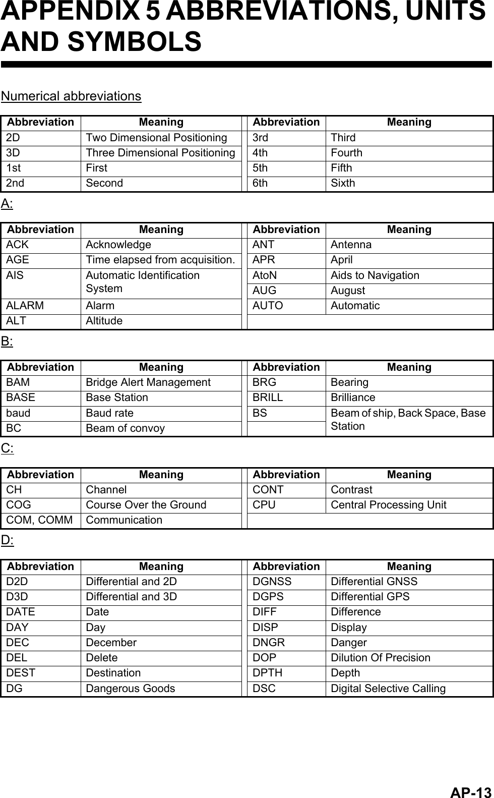
![AP-7APPENDIX 2 ALERTS, IDS, MEAN-INGS AND MEASURESThe FA-170 displays alerts at the bottom of the screen, as they occur. You can see all alerts, current and past, from the [ALERT LIST] screen. The ID for each alert is different, depending on whether there is a BAM (Bridge Alert Management) system or an AMS (Alert Management System) connected.The table on the following page shows the alert ID, displayed message, meaning and measures for each alert.Note 1: Detection of RX malfunctionNote 2: Detection of TX malfunctionMPU detects TX malfunction (ID:001) in the following cases:Each active alert entry is accompanied by an alert icon, indicating the state of the alert. The alert icons displayed on the FA-170 are listed in the table below with a brief description.1) Detection of TDMA RX malfunctionFrequency errorPLL chip on TRX-PWR board generates lock or unlock signal for synthesizer.MPU watches and sets status flag which reflects data of ALR sentence.ID 003 for RX1, ID 004 for RX22) Detection of DSC RX malfunctionGeneral errorA DSC error will occur when the FA-170 cannot detect a correct signal strength from the DSC receive circuit 120 seconds.1) The signal indicated "LOCK" is not received from the PLL chip on the TRX-PWR board.2) The voltage of monitoring signal on the TRX-PWR board is abnormal. The reason for TRX-PWR board malfunction can be a hardware problem or software problem causing a continuous transmission that exceeds 250 msec.Note: The hardware stops automatically because of the continuous transmission.3) Invalid MMSI4) An excessively high VSWR (Voltage Standing Wave Ratio) for the AIS antenna de-tected.WarningIcon Priority MeaningActive-unacknowledged notification, icon is flashing.*Warning Active-silenced notification, icon is flashing.**: Flashing at 0.5 second intervals.Warning Rectified-unacknowledged notification, icon is flashing.*Warning Active-responsibility transferred notification, icon is lit steadily.Warning Active-acknowledged notification, icon is lit steadily.Caution Active, icon is lit steadily.Icon Priority Meaning](https://usermanual.wiki/Furuno-USA/9ZWFA170.User-Manual-II/User-Guide-2884868-Page-36.png)
![APPENDIX 2 ALERTS, IDS, MEANINGS AND MEASURESAP-8Alert ID Displayed message Meaning Measures(BAM ID)001(501)TX MALFUNCTION Transmission stopped due to a failure.Check antenna and FA-170 connections. Check that the Own Ship MMSI is set. Consult your dealer if the problem is not rectified.002(502)LEGACY/ALERT IF1: ANTENNA VSWR EX-CEEDS LIMITALERT IF2: ANTENNA MALFUNCTIONHigh VSWR for the AIS an-tenna detected.Check the antenna. Consult your dealer if the problem is not rectified.003(503)RX CHANNEL 1 MAL-FUNCTIONRX1 failure. Circuit board may be dam-aged. Contact your dealer.004(504)RX CHANNEL 2 MAL-FUNCTIONRX2 failure.005(505) *1RX CHANNEL 70 MAL-FUNCTIONFailed to receive DSC mes-sage.007(507) *1UTC SYNC INVALID No synchronization with UTC.Internal GPS has no fix. Check weather and surround-ing for obstacles. If the error appears frequently, contact your dealer.t008(508) *1MKD CONNECTION LOSTCommunication failure be-tween the transponder and the monitor unit.Check connection between units. Consult your dealer if the problem is not rectified.009(509) *1INT/EXT GNSS POSI-TION MISMATCHMismatch of position data between internal GNSS and external GNSS. After taking into account the antenna position, there is a difference of over 100 m.Check calibration and location setting for both GPS antennas.010(510) *1NAV STATUS INCOR-RECTMismatch between ship’s speed and [NAVSTATUS] information.Check [NAV STATUS] menu settings. Adjust settings appropriately.011(511)*1LEGACY/ALERT IF1: HEADING SENSOR OFFSETALERT IF2: MIS-MATCH BETWEEN HDG AND COGMismatch between COG and HDT. There is a difference of over 45° for more than five minutes at a speed of over five knots.Check connection to sensor.014(514) ACTIVE AIS-SART AIS-SART message receivedCheck the message.025(525)EXTERNAL EPFS LOSTSignal from external navigational aids lost or interrupted.Check connection to EPFS devices.](https://usermanual.wiki/Furuno-USA/9ZWFA170.User-Manual-II/User-Guide-2884868-Page-37.png)
![APPENDIX 2 ALERTS, IDS, MEANINGS AND MEASURESAP-9Note 1: The Alert IDs listed in parentheses are output when the FA-170 is connected to a BAM (Bridge Alert Management) system.Note 2: Alert ID 600950 is only output when a BAM (Bridge Alert Management) is connected and is given “Caution” priority level.Note 3: Where the [ALERT MODE] is set to [Legacy Ed.1/Ed.2], alert priority level for all alerts is fixed at “Warning”.Note 4: Where the [ALERT MODE] is set to [ALERT IF1] or [ALERT IF2] the alerts shown with “*1” in the table above are assigned “Caution” priority level.026(526)NO POSITION SEN-SOR IN USENo position data available. Check connection to sensor.029(529)NO VALID SOG IN-FORMATIONSOG information is invalid.030(530)NO VALID COG IN-FORMATIONCOG information is invalid.032(532) *1HEADING LOST / IN-VALIDHDG information is lost or invalid.035(535) *1NO VALID ROT INFOR-MATIONNo ROT information available.600950 BAM COM ERROR Communication failure between the BAMS and the transponder unit.Check connection between unit and BAM.Alert ID Displayed message Meaning Measures(BAM ID)](https://usermanual.wiki/Furuno-USA/9ZWFA170.User-Manual-II/User-Guide-2884868-Page-38.png)