Furuno USA 9ZWFA170 Automatic Identification Systems User Manual OME 44900 A
Furuno USA Inc Automatic Identification Systems OME 44900 A
UserManual.wiki
>
Furuno USA
>
9ZWFA170 User Manual
>
User Manual
Contents
1.
Installation Manual
2.
Installation Manual II
3.
User Manual
4.
User Manual II
User Manual
Navigation menu
Upload a User Manual
Namespaces
Wiki Guide
HTML
PDF
Info
Views
User Manual
Discussion / Help
Navigation

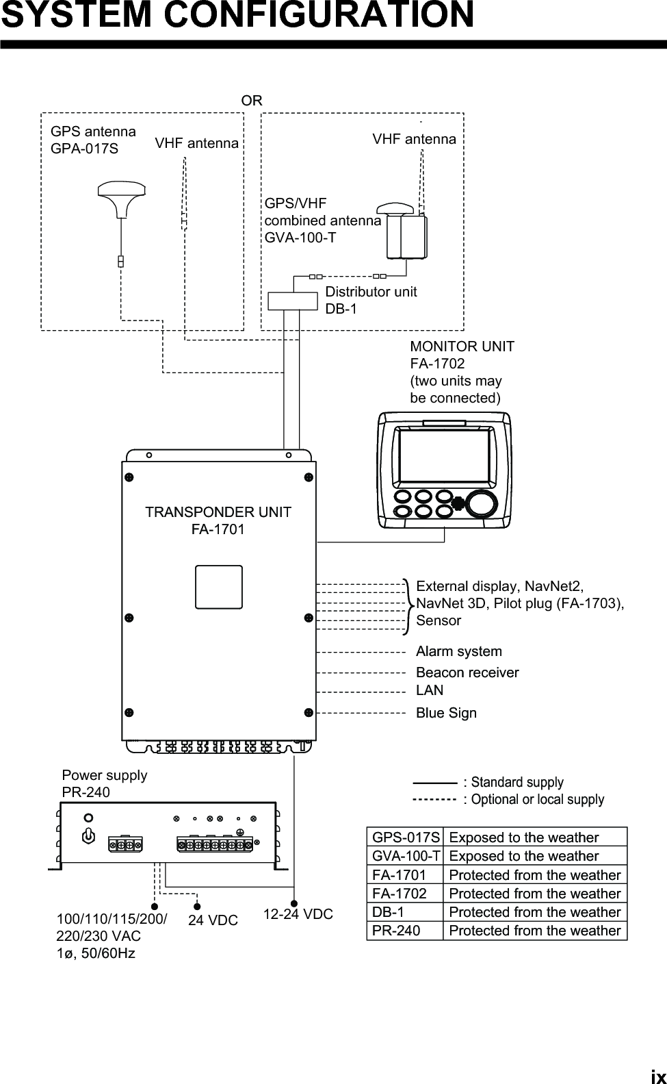
![vTABLE OF CONTENTSFOREWORD.................................................................................................................. viiSYSTEM CONFIGURATION .......................................................................................... ix1. OPERATION ..........................................................................................................1-11.1 Description of Controls ...............................................................................................1-11.2 How to Turn the Power On and Off ............................................................................1-21.3 How to Adjust the Panel and Display Brilliance..........................................................1-31.4 Display Overview........................................................................................................1-41.5 Menu Overview...........................................................................................................1-51.5.1 Menu operating procedure .............................................................................1-51.5.2 How to select a menu option ..........................................................................1-61.5.3 How to enter numeric data .............................................................................1-61.5.4 How to use the software keyboard for alphanumeric input ............................1-61.6 How to Enter Voyage-Related Data ...........................................................................1-71.7 How to Set the Notification .......................................................................................1-101.8 How to Select a Display............................................................................................1-111.8.1 Plotter display...............................................................................................1-121.8.2 Target list......................................................................................................1-141.8.3 Dangerous (target) list..................................................................................1-151.8.4 How to interpret the [TARGET DETAIL] screen ...........................................1-161.8.5 Own ship data ..............................................................................................1-181.8.6 Alert display..................................................................................................1-191.9 Messages .................................................................................................................1-201.9.1 How to send a message...............................................................................1-201.9.2 Receiving messages ....................................................................................1-221.9.3 How to use the message box (MSG BOX) ...................................................1-221.10 Regional Operating Channels ..................................................................................1-241.10.1 How to view channel information..................................................................1-241.10.2 How to edit/view regional channels ..............................................................1-251.11 How to Enable/Disable the Key Beep.......................................................................1-281.12 Long Range..............................................................................................................1-281.12.1 How to set up long range response..............................................................1-281.12.2 How to broadcast own ship data ..................................................................1-291.13 Pilot Plug (FA-1703, option) .....................................................................................1-301.14 Viewing Initial Settings..............................................................................................1-311.15 Setting for Time Difference.......................................................................................1-322. INLAND AIS OPERATION ....................................................................................2-12.1 How to Activate the Inland AIS ...................................................................................2-12.2 Selecting AIS Mode....................................................................................................2-22.3 How to Enter Voyage-Related Data ...........................................................................2-32.4 Static Data..................................................................................................................2-82.5 Target List and Dangerous Target List .......................................................................2-92.5.1 Target list........................................................................................................2-92.5.2 Dangerous (target) list..................................................................................2-112.5.3 How to interpret the [TARGET DETAIL] screen ...........................................2-112.6 Inland AIS Specific Messaging.................................................................................2-142.6.1 How to send a text message ........................................................................2-142.6.2 How to view a sent text message.................................................................2-162.6.3 ETA and RTA messages..............................................................................2-162.6.4 No. of persons message ..............................................................................2-202.6.5 EMMA warning message .............................................................................2-21](https://usermanual.wiki/Furuno-USA/9ZWFA170.User-Manual/User-Guide-2884867-Page-7.png)
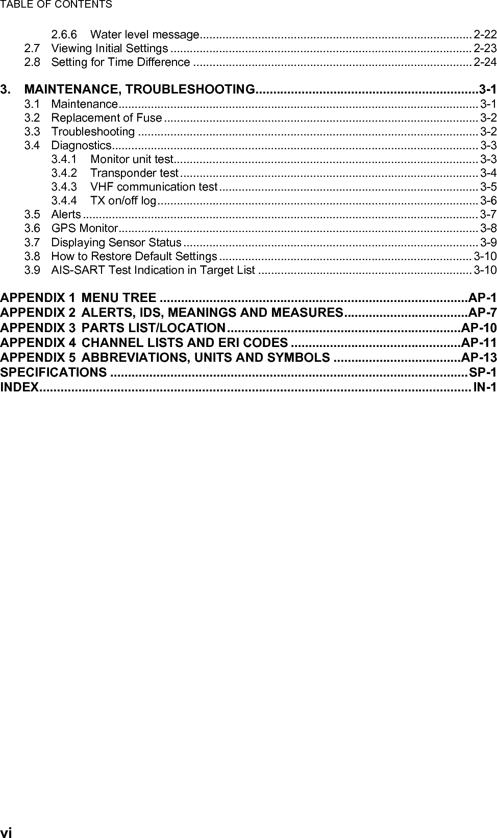

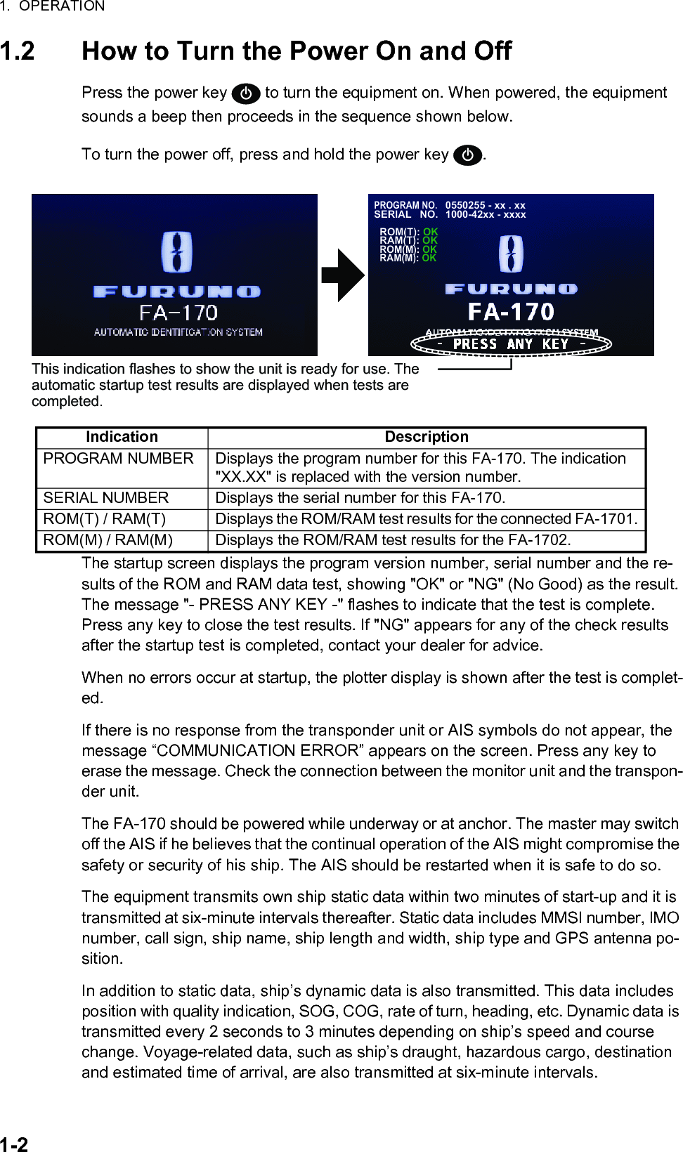
![1-11. OPERATION1.1 Description of ControlsNote: The nominal viewing distance is 70 cm.This manual uses the following terminology for the sake of brevity:No. Key name Function(s) when pressed1BRILL key • Displays brilliance setting pop-up window.• Switches between Day and Night display modes.2DISP key • Cycles through display screens.• Switches between Day and Night display modes when brilliance pop-up window is active.• Closes all active menu windows and returns to the last used display screen.3MENU/ESC key • Opens the menu.• Goes back one layer in the menu.• Closes the settings screen, when displayed, and returns to the menu.4Power key • Short press to turn the unit on.• Long press to turn the unit off.5NAV STATUS key Opens the [NAV STATUS] settings window.6ENT/ACK key • Confirms the currently selected item on the menu.• Confirms adjusted settings.• Acknowledge alerts.7 Arrow keys • Move the selection cursor.• Plotter display: or changes display range.• TARGET LIST display: or changes pages.• OWN INFORMATION display: or switches between informa-tion tabs.• ALERT display: or switches between the alert list and the alert log. or selects an alert.Terminology Example MeaningSelect Select [MSG]. Use the arrow keys to select [MSG]., , , Press . Press the corresponding arrow key.BCLASS A: CURSOR: SELECT : RANGEENT: NEXTDISPMMSINAME { NO NAME }TYPEPOSNSOGRNGHDGCOGBRG201502130130º135º225º10.0kn3 .0NM34º 31.1234´N135º 24.5678´EA761 2 345](https://usermanual.wiki/Furuno-USA/9ZWFA170.User-Manual/User-Guide-2884867-Page-13.png)
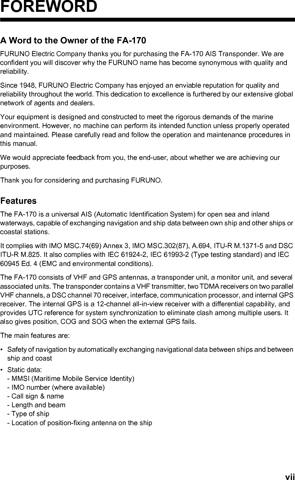
![1. OPERATION1-3The FA-170 starts receiving data from AIS-equipped ships as soon as it is turned on, and those ships’ locations are shown on the plotter display with the AIS symbol. (To learn more about the plotter display, see section 1.8.) With connection of a radar or ECDIS, the AIS target symbols may be overlaid on the radar or ECDIS.Note 1: If no navigation sensor is installed or a sensor such as a gyrocompass has failed, the AIS automatically transmits “not available data” to AIS-equipped ships.Note 2: The reporting intervals are as follows:Note 3: The screen refreshes slower in low ambient temperature.1.3 How to Adjust the Panel and Display BrillianceThe panel and display brilliance may be adjusted as follows:1. Press the BRILL key to show the [BRILL LEVEL SETUP] pop up window.If there is no operation within five seconds, the pop up window automatically clos-es.2. Press or to adjust the panel brilliance; or to adjust the display brilliance. The default panel and display brilliance settings are 15 and 15, respectively. To restore default settings see "How to Restore Default Settings" on page 3-10.)Note: The display brilliance can also be adjusted by pressing the BRILL key sev-eral times to cycle through brilliance levels.3. Press the ENT/ACK key to close the setting screen and apply the settings.How to switch between day and night displays1. Press the BRILL key to show the [BRILL LEVEL SETUP] pop up window.2. Press the DISP key while the pop up window is shown. The pop up window closes and the display settings change.3. Repeat the procedure to reverse the settings.Ship’s navigational status Nominal reporting intervalShip at anchor or moored or aground or not under command and not moving faster than 3 kn3 minutesShip at anchor or moored or aground or not under command and moving faster than 3 kn10 secondsShip speed 0-14 kn 10 secondsShip speed 0-14 kn and changing course 3 1/3 secondsShip speed 14-23 kn 6 secondsShip speed 14-23 kn and changing course 2 secondsShip speed faster than 23 kn 2 secondsShip speed faster than 23 kn and changing course 2 secondsDISPLAY (0 - 17) : 17PANEL (0 - 17) : 17: NIGHT : SETDISP ENTBRILL LEVEL SETUP (DAY)](https://usermanual.wiki/Furuno-USA/9ZWFA170.User-Manual/User-Guide-2884867-Page-15.png)
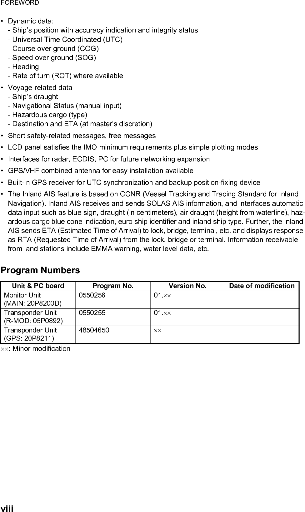
![1. OPERATION1-41.4 Display OverviewThe FA-170 display is made up of three major areas, as indicated in the Plotter display example figure below.The guidance box contents change according to the currently selected display or menu.The status bar shows various icons indicating the status of the equipment and shows the vessel’s own MMSI. The icons which can be displayed in the status bar are listed in the table below, along with a brief description.Icon Icon name DescriptionOperational status The dotted line rotates in a clockwise motion to indicate that the equipment is working normally.Contents mini-map Shows the location of the currently selected menu/display, indi-cated as a green box in the mini-map. The figure below shows the “locations”, as displayed in the mini-map.Class A AIS mode Displayed when the equipment is using Class A AIS mode.SOLAS AIS mode Displayed when the equipment is using SOLAS AIS mode.INLAND AIS mode Displayed when the equipment is using INLAND AIS mode.RX (Receive) Displayed when both A and B channel are set to receive mode (includes OFF). Shown only with CLASS A and INLAND AIS modes.TRX (Transmit) Displayed when either channel A or B are set to transmit mode. Shown only with CLASS A and INLAND AIS modes.HIGH (power) Displayed when the transmit power level is set to [HIGH].BCLASS A: CURSOR: FUNC : RANGEENT: NEXTDISPMMSINAME { NO NAME }TYPEPOSNSOGRNGHDGCOGBRG201502130130º135º225º10.0kn3 .0NM34º 31.1234´N135º 24.5678´EAStatus barCurrently selected display ormenu is shown in the middlesection of the screen.Guidance boxPlotterTarget listOwn (ship) informationNAV STATUSMenuAlert](https://usermanual.wiki/Furuno-USA/9ZWFA170.User-Manual/User-Guide-2884867-Page-16.png)
![1. OPERATION1-51.5 Menu OverviewYou can access the various functions of your FA-170 from the menu. If you get lost in operation, press the MENU/ESC key until you return to the main menu. A complete menu tree is provided in "MENU TREE" on page AP-1.Note: Inland AIS mode menus may differ from the menus shown in this chapter. For INLAND AIS mode, see "INLAND AIS OPERATION" on page 2-1.1.5.1 Menu operating procedure1. Press the MENU/ESC key to display the main menu.2. Select a main menu item, then press the ENT/ACK key.3. Select a sub-menu then press the ENT/ACK key.There are two types of sub-menus: option selection and data input. (Some sub-menus combine both.) Below are examples of each type of sub-menu.4. Select a menu item then press the ENT/ACK key.5. Depending on the menu selected, select an option or input alphanumeric data, then press the ENT/ACK key.6. Press the DISP key to close the menu.LOW (power) Displayed when the transmit power level is set to [LOW].SEND Displayed during message transmission. Not displayed when routine messages are transmitted. MSG Displayed when there are unread messages.MMSI Own ship MMSI.Icon Icon name DescriptionMSGSTATUSUSER SETINITIAL SETCH INFODIAGNOSTICSSERVICEMENU123456USER SET sub-menu (Option selection)TEST TARGET MMSI sub-menu(Numeric input)USER SETONONHIDEAUTOONKEY BEEPTIME DIFFAUTO SORTSART TESTLR RESPONSELR BROADCAST123456NOTIFICATION SET7ACTIVATE8::+00:00::::000000000TEST TARGET MMSI](https://usermanual.wiki/Furuno-USA/9ZWFA170.User-Manual/User-Guide-2884867-Page-17.png)
![1. OPERATION1-61.5.2 How to select a menu optionThe example below shows how to select an option from a menu.1) A window showing the options for the item selected is overlaid on the sub-menu. For example, the options for [KEY BEEP] are as shown below.2) Press or to select option desired, then press the ENT/ACK key.1.5.3 How to enter numeric dataThe example below shows how to enter numeric data.1) Select the appropriate numeric character. Press to display numeric characters cyclically in ascending order. Press to display numeric characters cyclically in descending order.2) Press or to shift the cursor.3) Repeat steps 1) and 2) to finish entering data.4) After entering all data, press the ENT/ACK key to register input.1.5.4 How to use the software keyboard for alphanumeric inputThe software keyboard appears when alphanumeric input is possible. Software key-board operation requires the use of the arrow keys and the ENT/ACK key.1. Referring to the figure above, press the arrow keys to select a character or key-board operation.2. Press the ENT/ACK key to confirm your selection.3. Repeat steps 1 and 2 to completed the alphanumeric input.4. Select [SET], then press the ENT/ACK key.ONOFFUSER SETONHIDEAUTOONKEY BEEPTIME DIFFAUTO SORTSART TESTLR RESPONSELR BROADCAST123456NOTIFICATION SET7ACTIVATE8::::Options window000000000TEST TARGET MMSICursor position is highlighted.Cursor position is shown as a blue bar.Backspace - Erase the character to the left of the cursor.Delete - Erase the character to the right of the cursor.Cursor locators - Press ► to move the cursor right, ◄ to move the cursor left.SET - Apply the changes.Current selection is highlighted in blue.Keyboard operation keysNo. of characters before cursorTotal characters inputMaximum characters allowed](https://usermanual.wiki/Furuno-USA/9ZWFA170.User-Manual/User-Guide-2884867-Page-18.png)
![1. OPERATION1-71.6 How to Enter Voyage-Related DataThere are six items on the [NAV STATUS] menu that you will need to enter at the start of a voyage.1. Press the NAV STATUS key to open the [NAV STATUS] menu. The [NAV STATUS] setting is selected by default2. If your navigational status is different from that shown, follow the procedure below. If it is the same as shown, go to step 3.1) Press the ENT/ACK key. The [NAV STATUS] options pop up window appears.2) Input the appropriate status, then press the ENT/ACK key. Refer to the data below to select appropriate navigational status.3. Select [DESTINATION], then press the ENT/ACK key. The software keyboard ap-pears for direct input.Enter the desired destination then press the ENT/ACK key. You can use up to 20 alphanumeric characters and enter up to 20 destinations.A list of destinations can also be accessed by selecting [DESTINATION LIST].• Navigational Status • Cargo type • ETA(LT/UTC) (Arrival time)• Destination • No. of persons • DraughtNAV STATUSNAV STATUS PWR-DRIVEN VESSEL PUSHING AHEAD OR TOWING ALONGSIDEKOBE [DESTINATION LIST]DESTINATIONETA[UTC]12/MAY 12:3224 WIG CARRYING DG, HS, OR, MP(OS)CARGO TYPEDRAUGHT 0 . 0m1NO. OF PERSONS: CURSOR: SELECT12ENT::::::: TAB00: UNDERWAY USING ENGINE01: AT ANCHOR02: NOT UNDER COMMAND03: RESTRICTED MANEUVERABILITY04: CONSTRAINED BY HER DRAUGHT05: MOORED06: AGROUND07: ENGAGED IN FISHING08: UNDERWAY SAILING09: RESERVED FOR HIGH SPEED CRAFT (HSC)*110: RESERVED FOR WING IN GROUND (WIG)*211: PWR-DRIVEN VESSEL TOWING ASTERN12: PWR-DRIVEN VESSEL PUSHING AHEAD OR TOWING ALONGSIDE13: RESERVED FOR FUTURE USE14: AIS-SART (ACTIVE), MOB-AIS, EPIRB-AIS*315: DEFAULT (ALSO USED BY SART, MOB, EPIRB UNDER TEST)*1: RESERVED FOR FUTURE AMENDMENT OF NAVIGATIONAL STATUS FOR SHIPS CARRYING DG, HS, OR MP, OR IMO HAZARD OR POLLUTANT CATEGORY C, HIGH SPEED CRAFT (HSC)*2: RESERVED FOR FUTURE AMENDMENT OF NAVIGATIONAL STATUS FOR SHIPS CARRYING DANGEROUS GOODS (DG), HARMFUL SUBSTANCES (HS) OR MARINE POLLUTANTS (MP), OR IMO HAZARD OR POLLUTANT CATEGORY A, WING IN GRAND (WIG)*3: Not selectable for this type of equipment.DESTINATION LIST<EDIT>SEATTLEOSAKASAN FRANCISCOYOKOHAMABRISBANE= NO ENTRY == NO ENTRY =0706050403020101 / 2008DESTINATIONABERDEEN<COPY>CURSOREXEC FUNCBACK<PASTE><CUT><SET>Operation selection bar<EDIT><COPY><PASTE><CUT><SET>Destinations](https://usermanual.wiki/Furuno-USA/9ZWFA170.User-Manual/User-Guide-2884867-Page-19.png)
![1. OPERATION1-8Referring to operation descriptions in the table below, press or to select an operation, press or to select an entry in the list, then press the ENT/ACK key to confirm the selection.4. Select [ETA (LT/UTC)], then press the ENT/ACK key. The settings pop up window shown below appears.Note 1: The ETA indication appears as "ETA [LT]" when there a time offset is set from [TIME DIFF] in the [USER SET] menu. When the setting for [TIME DIFF] is not changed from the default (+00:00) setting, the ETA indication appears as "ETA [UTC]".Note 2: Where a GPS is not connected, or the signal is lost/interrupted, the ETA indication appears as ETA [UTC]. Further, the settings pop up window displays "NOTE: INPUT THE UTC" at the bottom of the pop up window.5. Set the ETA date and time, referring to the figure above, then press the ENT/ACK key.6. Select [CARGO TYPE], then press the ENT/ACK key. The settings pop up win-dow shown below appears.7. Select type of vessel/cargo, referring to the table on the following page, then press the ENT/ACK key.Note 1: Only the second digit for the type of vessel is entered here; the first digit is entered on the [INITIAL SET] menu, during installation.Note 2: When [Tanker] is selected and the Nav status is [Moored], output power is automatically switched to 1 W when SOG is less than 3 knots. Further, in the above condition, when SOG becomes higher than 3 knots, a beep sounds. (The pop-up message "TX POWER CHANGED" also appears to notify you that the Tx power has changed). To erase the pop-up message, press the ENT/ACK key or reduce SOG to below 3 knots.Operation Description<SET> Set the currently selection as the destination.<EDIT> Rename the selected destination.<CUT> Cut the current selection to temporary memory, leaving the entry empty. The destination can now be pasted as a different entry.<COPY> Copy the current selection to temporary memory. The destination can now be pasted as a different entry.<PASTE> Paste the entry in temporary memory.Note 1: Only one entry can be stored in temporary memory at a time. If you <CUT> two entries successively, the first is deleted.Note 2: Entries over-written with <PASTE> cannot be restored.12 / 10 12:32ETA (UTC)ETA monthETA day ETA timein 24hr format24CARGO TYPE](https://usermanual.wiki/Furuno-USA/9ZWFA170.User-Manual/User-Guide-2884867-Page-20.png)
![1. OPERATION1-98. Select [DRAUGHT], then press the ENT/ACK key.9. Input the ship’s draught (setting range: 0 m to 25.5 m) then press the ENT/ACK key.10. Select [NO. OF PERSONS], then press the ENT/ACK key.11. Input total number of persons aboard the ship (setting range: 0-8191) then press the ENT/ACK key. Enter 8191 for total greater than 8190.12. Press the DISP key to close the menu.WIG: Wing in groundHSC: High speed craftDG: Dangerous goodsHS: Harmful substancesMP: Marine pollutants0-9: Undefined10 FUTURE USE ALL SHIPS OF THIS TYPE 60 PASSENGER SHIPS ALL SHIPS OF THIS TYPE11 FUTURE USE CARRYING DG, HS, OR MP(X) 61 PASSENGER SHIPS CARRYING DG, HS, OR MP(X)12 FUTURE USE CARRYING DG, HS, OR MP(Y) 62 PASSENGER SHIPS CARRYING DG, HS, OR MP(Y)13 FUTURE USE CARRYING DG, HS, OR MP(Z) 63 PASSENGER SHIPS CARRYING DG, HS, OR MP(Z )14 FUTURE USE CARRYING DG, HS, OR MP(OS) 64 PASSENGER SHIPS CARRYING DG, HS, OR MP(OS)15 FUTURE USE 65 PASSENGER SHIPS FUTURE USE16 FUTURE USE 66 PASSENGER SHIPS FUTURE USE17 FUTURE USE 67 PASSENGER SHIPS FUTURE USE18 FUTURE USE 68 PASSENGER SHIPS FUTURE USE19 FUTURE USE NO ADDITIONAL INFORMATION 69 PASSENGER SHIPS NO ADDITIONAL INFORMATION20 WIGALL SHIPS OF THIS TYPE 70 CARGO SHIPSALL SHIPS OF THIS TYPE21 WIG CARRYING DG, HS, OR MP(X) 71 CARGO SHIPS CARRYING DG, HS, OR MP(X)22 WIG CARRYING DG, HS, OR MP(Y) 72 CARGO SHIPS CARRYING DG, HS, OR MP(Y)23 WIG CARRYING DG, HS, OR MP(Z ) 73 CARGO SHIPS CARRYING DG, HS, OR MP(Z )24 WIG CARRYING DG, HS, OR MP(OS) 74 CARGO SHIPS CARRYING DG, HS, OR MP(OS)25 WIG FUTURE USE 75 CARGO SHIPS FUTURE USE26 WIG FUTURE USE 76 CARGO SHIPS FUTURE USE27 WIG FUTURE USE 77 CARGO SHIPS FUTURE USE28 WIG FUTURE USE 78 CARGO SHIPS FUTURE USE29 WIG NO ADDITIONAL INFORMATIONNO ADDITIONAL INFORMATION79 CARGO SHIPS NO ADDITIONAL INFORMATION30 FISHING 80 TANKER(S)TANKER(S)TANKER(S)TANKER(S)TANKER(S)TANKER(S)TANKER(S)TANKER(S)TANKER(S)TANKER(S)ALL SHIPS OF THIS TYPE31 TOWING 81 CARRYING DG, HS, OR MP(X)32 LENGTH OF THE TOW EXCEEDS 200M OR BREADTH EXCEEDS 25M 82 CARRYING DG, HS, OR MP(Y)33 ENGAGED IN DREDGING OR UNDERWATER OPERATIONS 83 CARRYING DG, HS, OR MP(Z)34 ENGAGED IN DIVING OPERATIONS 84 CARRYING DG, HS, OR MP(OS)35 ENGAGED IN MILITARY OPER ATIONS 85 FUTURE USE36 SAILING 86 FUTURE USE37 PLEASURE CRAFT 87 FUTURE USE38 FUTURE USE 88 FUTURE USE39 FUTURE USE 89 NO ADDITIONAL INFORMATION40 HSCALL SHIPS OF THIS TYPE 90 OTHER TYPE OF SHIPALL SHIPS OF THIS TYPE41 HSC CARRYING DG, HS, OR MP(X) 91 OTHER TYPE OF SHIP42 HSC CARRYING DG, HS, OR MP(Y) 92 OTHER TYPE OF SHIP43 HSC CARRYING DG, HS, OR MP(Z ) 93 OTHER TYPE OF SHIP )44 HSC CARRYING DG, HS, OR MP(OS) 94 OTHER TYPE OF SHIP45 HSC FUTURE USE 95 OTHER TYPE OF SHIP46 HSC FUTURE USE 96 OTHER TYPE OF SHIP47 HSC FUTURE USE 97 OTHER TYPE OF SHIP48 HSC FUTURE USE 98 OTHER TYPE OF SHIP49 HSC 99 OTHER TYPE OF SHIPCARRYING DG, HS, OR MP(X)CARRYING DG, HS, OR MP(Y)CARRYING DG, HS, OR MP(ZCARRYING DG, HS, OR MP(OS)FUTURE USEFUTURE USEFUTURE USEFUTURE USE50 PILOT VESSEL51 SEARCH AND RESCUE VESSELS52 TUGS53 PORT TENDERS54 VESSELS WITH ANTI-POLLUTION FACILITIES OR EQUIPMENT55 LAW ENFORCEMENT VESSELS 56 SPARE-FOR ASSIGNMENTS TO LOCAL VESSELS57 SPARE-FOR ASSIGNMENTS TO LOCAL VESSELS58 MEDICAL TRANSPORTS59SHIPS & AIRCRAFT OF STATES NOT PARTIES TO AN ARMED CONFLICT NO ADDITIONAL INFORMATION00 .0DRAUGHT0001NO. OF PERSONS](https://usermanual.wiki/Furuno-USA/9ZWFA170.User-Manual/User-Guide-2884867-Page-21.png)
![1. OPERATION1-101.7 How to Set the NotificationThe [NOTIFICATION SET] menu is used to set the following items:• Enable or disable the alert buzzer.• Notifications for received [ADDRESSED] and [BROADCAST] messages.• Notifications for collision detection.To change the settings in the [NOTIFICATION SET] menu, do the following:1. Press the MENU/ESC key to open the main menu.2. Select [USER SET], then press the ENT/ACK key.3. Select [NOTIFICATION SET], then press the ENT/ACK key. The [NOTIFICATION SET] screen appears.4. Select the [BUZZER] item be-low [ALERT], then press the ENT/ACK key. The settings pop up window appears.5. Select [ON] to enable the alert buzzer, or select [OFF] to disable the alert buzzer, then press the ENT/ACK to confirm the setting.6. Select the [ADDRESSED] item below [RX MESSAGE], then press the ENT/ACK key. The settings pop up window appears.7. Select the appropriate setting, referring to the table below, then press the ENT/ACK key.8. Set the notifications for [BROADCAST] RX messages and [COLLISION DETECT] in the same manner.9. Press the DISP key to close the menu.Setting DescriptionPOPUP + BUZZER Enable both the pop up indication and the buzzer.POPUP Enable only the pop up indication. (No buzzer.)OFF Disable notifications.NOTIFICATION SET[ALERT]ADDRESSEDBUZZERBROADCAST[RX MESSAGE][COLLISION DETECT ]INDICATION: CURSOR: SELECT : BACKONPOPUPPOPUP + BUZZERPOPUPENT ENT::::](https://usermanual.wiki/Furuno-USA/9ZWFA170.User-Manual/User-Guide-2884867-Page-22.png)
![1. OPERATION1-111.8 How to Select a DisplayUse the DISP key to select a display. Each time the key is pressed, the display chang-es in the sequence shown below.The [DANGEROUS LIST] and [TARGET LIST] are displayed dependent on which list was last displayed. For example, if the [DANGEROUS LIST] is viewed at any time, the [TARGET LIST] is hidden in the above cycle and can only be viewed by sorting the [DANGEROUS LIST]. See section 1.8.2 for details.DANGEROUS LIST 12:32:019-16 (108): CURSOR: FUNCENT: PAGE : NEXTDISPSAMPLE SHIP 003 3 .5 100.0 0SAMPLE SHIP 004 3 .6 110.0SAMPLE SHIP 005 3 .7 120.0 0SAMPLE SHIP 006 3 .8 130.0 0SAMPLE SHIP 007 3 .9 140.0 0SAMPLE SHIP 008 3 .1 150.0 0SAMPLE SHIP 002 3 .4 090.0 0SAMPLE SHIP 002 3 .3 080.0 0NAME/MMSI/TYPE RNG[NM] BRG[ ° ] AGE[ ‘ ]BAASARBALERT: CURSOR: TAB : NEXTDISP30/ JAN 17:20 TX MALFUNCTION29/ JAN 17:50 ANTENNA VSWR EXCEEDS LIMIT28/ JAN 08:20 RX CHANNEL 1 MALFUNCTION27/ JAN 12:35 RX CHANNEL 2 MALFUNCTION26/ JAN 03:45 GENERAL FAILURE25/ JAN 09:36 ACTIVE AIS-SARTID:001 : TX MALFUNCTIONTIME [UTC] ALERT 01 /06LIST : 6 LOG : 20OWN INFORMATION: TAB : NEXTDISPSENSOR VOYAGE IDENTITY SCALEUTC12/NOV/2014 17 :20 :0034 º 44 .5000 ´N130º135 .0º135 º 21.3000 ´E108 . 7 º/min ( )10 .0 knHIGHUNUSEDPOSN PARAIMHDGCOGROTSOGEXTERNALDGPS2Dangerous target listNote: The last displayed list is shown.BCLASS A: CURSOR: SELECT : RANGEENT: NEXTDISPMMSINAME { NO NAME }TYPEPOSNSOGRNGHDGCOGBRG201502130130º135º225º10.0kn3 .0NM34º 31.1234´N135º 24.5678´EAAlert listOwn (ship) informationTARGET LIST12:32:0181-88(334): CURSOR: FUNCENT: PAGE : NEXTDISPNAME/MMSI/TYPE RNG[NM] BRG[ º ] AGE[ ‘ ]BAASARBSAMPLE SHIP 003 3 .5 100.0 0SAMPLE SHIP 004 3 .6 110.0SAMPLE SHIP 005 3 .7 120.0 0SAMPLE SHIP 006 3 .8 130.0 0SAMPLE SHIP 007 3 .9 140.0 0SAMPLE SHIP 008 3 .1 150.0 0SAMPLE SHIP 002 3 .4 090.0 0SAMPLE SHIP 002 3 .3 080.0 0Target listPlotter display](https://usermanual.wiki/Furuno-USA/9ZWFA170.User-Manual/User-Guide-2884867-Page-23.png)
![1. OPERATION1-121.8.1 Plotter displayThe plotter display, which automatically appears after the power-on sequence, shows various information for AIS-equipped ships, AIS-SARTs, etc. within the range select-ed. Data for ship targetA target marker (hollow triangle) indicates the presence of a vessel equipped with AIS in a certain location and course. To view detailed information about a vessel, see paragraph 1.8.2.If two or more targets occupy a similar position, the display priority order is: selected target (surrounded by a broken box, as shown in the example below) > non-selected target.How to operate the plotter display1. Press the DISP key to show the plotter display.2. Press or to select a range. The available ranges are (in nm): 0.125, 0.25, 0.5, 0.75, 1.5, 3, 6, 12, and 24.3. Press or to select a target. The selected target is highlighted in a blue col-ored broken box. Further, the selected target’s basic data are displayed on the right-side of the screen.4. To view a target’s detailed data, or to sort the target list, select the desired target, then press the ENT/ACK key. The [FUNCTION] pop up window appears.• [SORT (NORMAL)]: Press to display and sort the [TARGET LIST] into range order.DANGER is displayed here when a target is calculated to be on a collision course with your vessel. If no signal is received from target, LOST is displayed. The target data is deleted seven minutes after the loss of signal from the target.: FUNC : RANGEENT: NEXTDISPBCLASS AMMSINAME { NO NAME }TYPEPOSNSOGRNGHDGCOGBRG201502130130º135º225º10.0kn3 .0NM34º 31.1234´N135º 24.5678´EAMMSI: Target’s MMSI NAME: Target vessel’s name (if available)POSN: Target’s last known positionHDG: Target’s headingSOG: Target’s Speed Over GroundCOG: Target’s Course Over GroundRNG: Range to target from Own ShipBRG: Bearing to targetTarget type (CLASS A, CLASS B, BS, AtoN, SAR, AIS-SART, MOB-AIS, EPIRB-AIS, INLAND)MMSINAME{ NO NAME }POSNSOGRNGHDGCOGBRG201502130130º135º225º10.0kn3 .0NM34º31.1234´N135º24.5678´EKey guidance barSelected targetOwn Ship symbolAIS-SARTTarget (black)Base stationBFor a full list of AIS icons, and their meanings, see Appendix 5, at the back of this manual.: CURSORFUNCTIONNEW MSGVIEW DETAIL SORT(DANGER)SORT(NORMAL)NAME REQUESTENT](https://usermanual.wiki/Furuno-USA/9ZWFA170.User-Manual/User-Guide-2884867-Page-24.png)
![1. OPERATION1-13• [SORT (DANGER)]: Press to display and sort the [DANGEROUS TARGET LIST] in range order.Note: When [SORT (DANGER)] is selected, all non-dangerous targets are hid-den on the plotter display and the plotter screen is surrounded by a red box, as shown in the figure below.To show any targets which were hidden by this option, select [SORT (NOR-MAL)] from the [FUNCTION] pop up window.• [VIEW DETAIL]: Press the ENT/ACK key to open the [TARGET DETAIL] screen.• [NEW MSG]: Press to open the text input window to create an AIS message to the selected target.• [NAME REQUEST]: Press to send a name request to the target vessel’s AIS.Note: Name requests cannot be sent to the same target within a short period, regardless of target. If you have requested the name of a target too soon after the last request, the pop up message "CANNOT REQUEST NAME" appears. Wait a short while before requesting the name again.Note 1: A target is declared a lost target under the conditions shown in the table be-low. A target is erased from the screen seven minutes (For AIS-SART, 18 minutes) after no signal is received from the target.Note 2: When a target is considered to be on a collision course, the audible alert sounds (if active). Take suitable measures to avoid collision.Note 3: "DANGER" appears next to the target type when a target is considered to be on a collision course. Further, when a target becomes a lost target, "LOST" appears next to the target type.CLASS A: CURSOR: SELECT : RANGEENT: NEXTDISPMMSINAME { NO NAME }TYPEPOSNSOGRNGHDGCOGBRG201502130130º135º225º10.0kn3 .0NM34º 31.1234´N135º 24.5678´EABPlotter surrounded by red line. Only dangerous targets are displayed.Ship’s navigational status Target declared as lost target after:Class AClass BShip at anchor or moored or aground or not under command and not moving faster than 3 kn.Ship at anchor or moored or aground or not under command and moving at more than 3 kn.0 to 14 kn speed0 to 14 kn speed with course change50 seconds50 seconds14 to 12 kn speed 30 seconds14 to 12 kn speed with course change 30 secondsSpeed higher than 23 kn 10 secondsSpeed over ground less than 2 kn 7 minutesSpeed over ground 2 kn or higher 150 secondsSpeed higher than 23 kn with course change 10 seconds50 seconds7 minutes](https://usermanual.wiki/Furuno-USA/9ZWFA170.User-Manual/User-Guide-2884867-Page-25.png)
![1. OPERATION1-141.8.2 Target listThe [TARGET LIST] can store up to 2048 AIS targets and AIS-SARTs being detected by the FA-170 across several pages, in the order which they are detected. The list can be sorted in range order, from closest to farthest.Note: The last viewed list is displayed when the DISP key is pressed to show either the [TARGET LIST] or the [DANGEROUS LIST]. To view the [TARGET LIST] when the [DANGEROUS LIST] is displayed, follow the procedure outlined in step 3 on the following page.1. Press the DISP key until the [TARGET LIST] is displayed.The [NAME/MMSI/TYPE] column of the [TARGET LIST] displays the target ves-sel’s type in the following formats:Where the target type is CLASS A/CLASS B/AtoNThe name of the vessel is displayed when the name data is available. Where the name data is not available, the vessel’s MMSI is displayed.Where the target type is SAR(VESSEL/AIRCRAFT)/SART/MOB/EPIRBThe format in which data is displayed is listed in the table below.Where the target type is BASE STATION"BS:(Base station’s MMSI)" is displayed.Note 1: If there is no data for the target selected, the fields are displayed as "=NO TARGET=".Note 2: Targets are automatically sorted in range order (closest to furthest) when no key is operated for 30 seconds. Target order is then updated every five sec-onds.Active AIS-SARTs take priority and are displayed at the top of the list.Note 3: When [AUTO SORT] on the [USER SET] menu is [OFF], the range and bearing to a target are updated. However, target order is not updated. To manu-ally sort targets, see step 2.Note 4: To select a target on the plotter display, press or to select the target then press the ENT/ACK key. Press to cycle through targets from nearest to furthest; to cycle through targets from furthest to nearest.TYPE Display format TYPE Display formatSAR vessel "SAR/VESSEL" MOB Active "MOB ACTIVE"SAR aircraft "SAR/AIRCRAFT" MOB Test "MOB TEST"SART Active "SART ACTIVE" EPIRB Active "EPIRB ACTIVE"SART Test "SART TEST" EPIRB Test "EPIRB TEST"TARGET LIST 12:32:0181-88(334): CURSOR: FUNCENT: PAGE : NEXTDISPNAME/MMSI/TYPE RNG[km] BRG[ º ] AGE[ ‘ ]BAASARBSAMPLE SHIP 003 3 .5 100.0 0SAMPLE SHIP 004 3 .6 110.0SAMPLE SHIP 005 3 .7 120.0 0SAMPLE SHIP 006 3 .8 130.0 0SAMPLE SHIP 007 3 .9 140.0 0SAMPLE SHIP 008 3 .1 150.0 0SAMPLE SHIP 002 3 .4 090.0 0SAMPLE SHIP 002 3 .3 080.0 0NAME/MMSI/TYPE: Target’s MMSI, name or type is displayed. Where name data is available, the vessel name is displayed.RNG[km]: Range from OS to target.BRG[ º ]: Bearing to target.AGE[ ‘ ]: Time (in minutes) since the target data was last updated.Target type symbols.See Appendix 5 of the operator’s manual for a full list of AIS symbols and their meanings.Selected target is highlighted.Time at which the list was last sorted.Currently displayed target group. Total detected targets is displayed in brackets.](https://usermanual.wiki/Furuno-USA/9ZWFA170.User-Manual/User-Guide-2884867-Page-26.png)
![1. OPERATION1-152. Press or to scroll through the first 100 targets, press or to scroll through the targets in groups of 8 (next/previous 8 targets).The indication "NEXT 100 TARGETS" appears at the bottom of the list if more tar-gets are available. Select the indication, then press the ENT/ACK key to show the next 100 targets.The indication "PREVIOUS 100 TARGETS" appears at the top of the list if there is one or more pages of targets before the one currently displayed. Select the in-dication, then press the ENT/ACK key to show the previous 100 targets.3. To view target data, or to sort the target list, select the desired target, then press the ENT/ACK key. The target list options pop up window is displayed.4. Press the DISP key to close the menu.1.8.3 Dangerous (target) listDangerous targets are targets which are calculated to be on a collision course with your vessel. When a dangerous target is detected, the target and its available details can be viewed in the [DANGEROUS TARGET LIST]. Note: The operations available from the [DANGEOUS TARGET LIST] are the same as the [TARGET LIST] operations.To view the [DANGEROUS LIST] when the [TAR-GET LIST] is displayed, follow the procedure outlined in step 3 of section 1.8.2.Note: If there are no dangerous targets detected, the fields are displayed as "=NO TARGET=".FUNCTIONNEW MSGVIEW DETAIL SORT(DANGER)SORT(NORMAL)NAME REQUESTENT• [SORT (NORMAL)]: Press ◄ to sort the [TARGET LIST] into range order. The closest target is displayed at the top of the list.• [SORT (DANGER)]: Press ► to display and sort the [DANGEROUS TARGET ]LIST in range order. The closest target is displayed at the top of the list.• [VIEW DETAIL]: Press the ENT/ACK key to open the [TARGET DETAIL] screen.• [NEW MSG]: Press ▲ to open the text input window to create an AIS message to the selected target.• [NAME REQUEST]: Press ▼ to send a name request to the target vessel’s AIS.Name requests cannot be sent to the same target within a short period, regardless of target. If you have requested the name of a target too soon after the last request, or the target is out of range, or the target has set their AIS to RX only mode, the pop up message "CANNOT REQUEST NAME" is displayed. Wait a short while before requesting the name again.DANGEROUS LIST12:32:019-16 (108): CURSOR: FUNCENT: PAGE : NEXTDISPSAMPLE SHIP 003 3 .5 100.0 0SAMPLE SHIP 004 3 .6 110.0SAMPLE SHIP 005 3 .7 120.0 0SAMPLE SHIP 006 3 .8 130.0 0SAMPLE SHIP 007 3 .9 140.0 0SAMPLE SHIP 008 3 .1 150.0 0SAMPLE SHIP 002 3 .4 090.0 0SAMPLE SHIP 002 3 .3 080.0 0NAME/MMSI/TYPE RNG[NM] BRG[ ° ] AGE[ ‘ ]BAASARBTarget type symbols. See Appendix 5 for a full list of AIS symbols and their meanings.NAME/MMSI/TYPE: Target’s MMSI, name or type is displayed. Where name data is available, the vessel name is displayed.RNG[NM]: Range from OS to target.BRG[ º ]: Bearing to target.AGE[ ‘ ]: Time (in minutes) since the target data was last updated.Selected target is highlighted.Time at which the list was last sorted.](https://usermanual.wiki/Furuno-USA/9ZWFA170.User-Manual/User-Guide-2884867-Page-27.png)
![1. OPERATION1-161.8.4 How to interpret the [TARGET DETAIL] screenThe [TARGET DETAIL] screen shows available detailed information about the select-ed target.Lost and dangerous targets have the appropriate icon displayed at the top right, as indicated in the lost target example below.There are five tabs available for viewing; [SENSOR], [VOYAGE], [IDENTITY], [SCALE] and [QUALITY]. Press or to change the tab currently displayed.The selected target’s bearing ([BRG]), range ([RNG]), [MMSI] and [NAME] are dis-played at the top of the screen regardless of the selected tab. For lost or dangerous targets, the appropriate icon is displayed at the top right of the screen.The information displayed on each tab varies, depending on the type of target select-ed.The tables on the following pages list each tab’s contents, along with a brief descrip-tion.SENSOR tabVOYAGE tabThe VOYAGE tab is only displayed for CLASS A target types. Contents DescriptionPOSN Target’s last known position. Displayed for all target types.ROT Target’s Rate Of Turn. Displayed only for CLASS A, SART, MOB and EPIRB target types.ALT Altitude. Displayed only for SAR VESSEL and SAR AIRCRAFT target types.SOG Target’s Speed Over Ground. Displayed only for CLASS A, CLASS B, SAR VESSEL, SAR AIRCRAFT, SART, MOB and EPIB target types.COG Target’s Course Over Ground. Displayed only for CLASS A, CLASS B, SAR VESSEL, SAR AIRCRAFT, SART, MOB and EPIB target types.HDG Target’s last known heading. Displayed only for CLASS A, CLASS B, SART, MOB and EPIRB target types.Contents DescriptionNAV STATUS Target’s navigational status (see section 1.6 for details).DESTINATION Target’s destination.ETA Target’s Estimated Time of Arrival at the above destination.TARGET DETAIL: TAB: TARGET : BACKMENUSENSOR VOYAGE IDENTITY SCALE QUALITYCLASS AFURUNOMARUTYPE34 º 44 .5000 ´N130 .0º135 .0º135 º 21.3000 ´E108 . 7 º/min ( )10 .0 knPOSNHDGCOGROTSOG225.4º3.02NMBRGRNG 201503030NAMEMMSILOSTAThe LOST icon is displayed for lost targets.The DANGER icon is displayed for dangerous targets.When data input to the FA-170 is interrupted or stopped, indications for all tabs appear as “----”.](https://usermanual.wiki/Furuno-USA/9ZWFA170.User-Manual/User-Guide-2884867-Page-28.png)
![1. OPERATION1-17IDENTITY tabThe IDENTITY tab is only displayed for CLASS A, CLASS B, SAR VESSEL, SAR AIR-CAFT and AtoN target types.SCALE tabThe SCALE tab is only displayed for SAR VESSEL, SAR AIRCRAFT and AtoN target types.QUALITY tabThe QUALITY tab is displayed for all target types.Contents DescriptionCALL SIGN Target’s call sign. Not displayed for AtoN target types.IMO NO. Target’s International Maritime Organization registration number.TYPE OF SHIP Target’s ship type. Displayed only for CLASS A and CLASS B target types.REAL AtoN Displayed as "YES" for physical aids to navigation, "NO" for virtual aids to nav-igation. Displayed only for AtoN target types.TYPE OF AtoN The type of aids to navigation. Displayed only for AtoN target types.VENDER ID Target’s AIS maker's ID. Displayed only for CLASS B target types.Contents DescriptionSHIP SIZE(LENGTH, BEAM) Target’s ship size (length, beam). Displayed for all above target types.ANT POSN(X,Y) Position of target’s antenna. Displayed for all above target types.DRAUGHT Target ship’s draught. Displayed only for CLASS A target types.PI Off-position indicator. Displayed only for AtoN target types.Contents DescriptionPA Position Accuracy for target ship. (HIGH: High accuracy, LOW: Low accuracy.)RAIM Target’s RAIM status. (USED: Using RAIM, UNUSED: Not using RAIM.).TIME STAMP Time at which the target was last detected. Not displayed for AIS base stations.POSN QUALITYTarget’s position quality. Possible position qualities are shown in the list below:Quality indication Meaning[NO POSITION] Position data not available.[MANUAL POSITION] Position data is input manually.[DEAD RECKONING POSITION] Position calculated by dead reckoning.[OUTDATED POSITION > 200 M] More than 200 m from last estimated position.[POSITION > 10 M] Difference of more than 10 m from last es-timated position.[POSITION WITH RAIM > 10 M] Difference of more than 10 m from last es-timated position.[POSITION < 10 M] Difference of less than 10 m from last esti-mated position.[POSITION WITH RAIM < 10 M] Difference of less than 10 m from last esti-mated position.[VALID POSN WITH NO TIME STAMP]No time stamp available.](https://usermanual.wiki/Furuno-USA/9ZWFA170.User-Manual/User-Guide-2884867-Page-29.png)
![1. OPERATION1-181.8.5 Own ship dataThe [OWN INFORMATION] display shows your ship’s data across four tabs. The in-formation displayed is shown in the figure below. This data should be checked once per voyage or once per month whichever is shorter. Data may be changed only on the authority of the master.The Officer of the Watch should periodically check position, SOG and sensor informa-tion for quality.The table below list each tab’s contents along with a brief description.Tab Item Description[SENSOR] [UTC], [LT] Date and time.[UTC]: Universal Time, Coordinated.[LT]: Local time.Note: For more information on these indica-tions, see section 1.15.[POSN] OS (Own Ship) position.[ROT] Rate of Turn.[SOG] Speed Over Ground.[PA] Positioning accuracy.[RAIM] RAIM status.[USED]: RAIM is currently in use.[UNUSED]: RAIM is not currently in use.[HDG] Heading.[COG] Course Over Ground.GPS status GPS currently in use.[VOYAGE] [NAV STATUS] Current navigational status.[DESTINATION] Current destination.[ETA [UTC]], [ETA [LT]] Estimate Time of Arrival (ETA) at the desti-nation.[NO. OF PERSONS] Number of people aboard your vessel.OWN INFORMATION: TAB : NEXTDISPSENSOR VOYAGE IDENTITY SCALEUTC12/NOV/2014 17 :20 :0034 º 44 .5000 ´N130 .0º135 .0º135 º 21.3000 ´E108 . 7 º/min ( )10 .0 knHIGHUNUSEDPOSN PARAIMHDGCOGROTSOGOWN INFORMATION: TAB : NEXTDISPSENSOR VOYAGE IDENTITY SCALENAV STATUSDESTINATIONETA (UTC)NO. OF PERSONSPWR-DRIVEN VESSEL PUSHING AHEAD OR TOWING ALONGSIDEKOBE185010/MAY 10:5112OWN INFORMATION: TAB : NEXTDISPSENSOR VOYAGE IDENTITY SCALEMMSINAMEIMO NO.CALL SIGNTYPE OF SHIPWIGARRYING DG, HS, OR, MP(OS)24@SEVEN@FURUNOMARU291 740 9170123456789OWN INFORMATION: TAB : NEXTDISP120m 60m0m60m80m 15m12 .3mSENSOR VOYAGE IDENTITY SCALESHIP SIZE LENGTH BEAMANT POSN Y XXYINTERNAL12EXTERNALDRAUGHT210SENSOR tab VOYAGE tabIDENTITY tabSCALE tabPress ► or ◄ to cycle through the tabs.EXTERNALDGPS2](https://usermanual.wiki/Furuno-USA/9ZWFA170.User-Manual/User-Guide-2884867-Page-30.png)
![1. OPERATION1-191.8.6 Alert displayThe alert display shows the date and time alerts were generated. For further details, see section 3.5.[IDENTITY] [MMSI] Own Ship’s MMSI.[NAME] Own Ship’s name.[IMO NO.] Own Ship’s IMO number.[CALL SIGN] Own Ship’s call sign.[TYPE OF SHIP] Own Ship’s vessel type. See section 1.6, step 7 for details.[SCALE] [SHIP SIZE] Own Ship’s length and beam.[ANT POSN] Antenna position.[INTERNAL]: position of internal antenna.[EXTERNAL]: position of external antenna.[DRAUGHT] Own Ship’s draught.Tab Item Description](https://usermanual.wiki/Furuno-USA/9ZWFA170.User-Manual/User-Guide-2884867-Page-31.png)
![1. OPERATION1-201.9 MessagesYou may send and receive messages via VHF channels, to a specified MMSI or all AIS-equipped ships in the area. Messages can be sent to warn of safety of navigation; for example, an iceberg sighted. Routine messages are also permitted.Short safety-related messages are only an additional means to broadcast safety infor-mation. They do not remove the requirements of the GMDSS.When a message is received, the equipment beeps and pop up appears, indicating the type of message received.Sent messages are stored in the [MSG BOX] (message box) under the [OUTBOX] tab.Received messages are stored in the [MSG BOX] under the [INBOX] tab.The FA-170 can store up to 20 transmitted and up to 20 received messages. When the [INBOX] or [OUTBOX] becomes full, the oldest message in the box is automatical-ly deleted to make room for the latest.1.9.1 How to send a messageThis procedure applies to Class A AIS, for Inland AIS, see section 2.6.1.1. Press the MENU/ESC key to open the main menu.2. Select [MSG], then press the ENT/ACK key.3. [NEW MSG] is selected. Press the ENT/ACK key. The [NEW MSG] screen ap-pears.4. [MSG TYPE] is selected, press the ENT/ACK key to change the type of message you wish to send. The options pop up shown below appears.5. Select the appropriate message type, then press the ENT/ACK key.For broadcast messages, skip to step 8.6. Select [TO], then press the ENT/ACK key. A numerical settings pop up appears.7. Input the MMSI of the ship you wish to send this message to, then press the ENT/ACK key to close the pop up. See section 1.5 for how to input data.MSGNEW MSGMSG BOX12NEW MSG TEXT( )MSG TYPE<SEND MSG>: CURSOR: SELECTADDRESSED: BACKENTMENU:TO 000000000:CH ALTERNATE:RETRY 3:TEXT( 0 / 85 )Use the software keyboard to enter the message here.:MSG TYPEBROADCASTADDRESSEDMessage to all vessels.Message to specified vessel only.](https://usermanual.wiki/Furuno-USA/9ZWFA170.User-Manual/User-Guide-2884867-Page-32.png)
![1. OPERATION1-218. Select [CH] (Channel), then press the ENT/ACK key. The channel select options pop up appears.9. Select the appropriate option, then press the ENT/ACK key.For broadcast messages, skip to step 12.10. Select [RETRY], then press the ENT/ACK key. The retry attempts setting pop up appears.11. Press to increase the retry attempts, to decrease the retry attempts. The maximum setting for retries is 3. Press the ENT/ACK key to apply the setting and close the pop up.12. Press to highlight the message text, then press the ENT/ACK to display the software keyboard.13. Input the new message text, referring to section 1.5.4. The maximum number of characters allowed is as follows:• BROADCAST: 90 characters.• ADDRESSED: 85 characters.14. Press or to highlight [<SEND MSG>] at the top right of the screen, then press the ENT/ACK key. A confirmation pop up appears.15. Select [YES] to send the message or [NO] to cancel the message, then press the ENT/ACK key.Note: The following pop up messages may be displayed during sending or after the message has been sent.Pop up message DescriptionMESSAGE SENT SUCCESSFULLY. Displayed after a message is sent successfully.NO TEXT IN MESSAGE Displayed when the message body is blank and <SEND MSG> is selected.FAILED TO SEND MESSAGE.(CODE:X)The message failed to send. The code (indicated as "X" in the example to the left) indicates the reason for the fail-ure."CODE:1" indicates that the message was not acknowl-edged by the recipient."CODE:2" indicates that the message failed to send.CHBOTH A & BONLY AONLY BALTERNATESends the same message to both channel A and channel B.Sends the message to channel A only.Sends the message to channel B only.Sends messages on alternating channels. In other words, if the last message sent on channel A, the next message is sent on channel B.](https://usermanual.wiki/Furuno-USA/9ZWFA170.User-Manual/User-Guide-2884867-Page-33.png)
![1. OPERATION1-221.9.2 Receiving messagesWhen a message is received, the equipment beeps and a pop up message appears on the screen. The table below lists the possible messages with a brief description. To enable/disable these pop ups, see section 1.7.1.9.3 How to use the message box (MSG BOX)How to view a received messageTo view message contents, follow the procedure below.1. Press the ENT/ACK to close the pop up window.2. Press the MENU/ESC key to show the main menu.3. Select [MSG], then press the ENT/ACK key.4. Select [MSG BOX], then press the ENT/ACK key. The [OUTBOX] tab is displayed by default. Press to display the [INBOX] tab.5. Select the message you wish to view, then press the ENT/ACK key. The message options pop up window shown below appears.Select [VIEW DETAIL], then press the ENT/ACK key to display the received mes-sage’s contents. The figure above shows an example of a received message.Select [NEW MSG], then press the ENT/ACK key to send a message back to this message’s sender.6. Press or to view other messages, press or to switch between viewing an [INBOX] message and an [OUTBOX] message.7. Press the DISP key to close the menu.Pop up message DescriptionTEXT MESSAGE RECEIVED. Displayed when a broadcast message is received.TEXT MESSAGE RECEIVED.MMSI/NAME.Displayed when an addressed message is received. MMSI appears by default, however, where name data is available, the vessel name is also displayed.MSG BOX TEXT ( )INBOX: 12OUTBOX: 10TIME [UTC]30 /MAY 17 : 20 BROADCASTBROADCASTENTERPRISEBROADCASTNEPTUNEBROADCASTNAUTILUS29 /MAY 16 :0528 /MAY 16 :1527 /MAY 17 :2026 /MAY 17 :2025 /MAY 17 :2024 /MAY 17 :20FROM 01 / 10: CURSOR: FUNCENT: TAB: BACKMENUIndication MeaningThis message has been viewed.This message is unviewed.Broadcast messageAddressed messageFUNCTIONVIEW DETAILNEW MSGMENUINBOX MSG DETAIL ( TEXT )MSG TYPE ADDRESSED28 / MAY 16 : 15987654321 / ENTERPRISEKLINGONS ON STBD BOW.TIME [UTC]TOTEXT( 21): BACK: BOX: MESSAGE](https://usermanual.wiki/Furuno-USA/9ZWFA170.User-Manual/User-Guide-2884867-Page-34.png)
![1. OPERATION1-23How to view sent messages1. Press the ENT/ACK to close the pop up window.2. Press the MENU/ESC key to show the main menu.3. Select [MSG], then press the ENT/ACK key.4. Select [MSG BOX], then press the ENT/ACK key. The [OUTBOX] tab is displayed by default.5. To view the contents of a message, highlight the message then press the ENT/ACK key. The message options pop up window appears.Select [VIEW DETAIL] to display the received message’s contents. The figure be-low shows an example of a received message.Select [NEW MSG] to send another message to the recipient.6. Press or to view other messages, press or to switch between viewing an [INBOX] message and an [OUTBOX] message.7. Press the DISP key to close the menu.MSG BOX ( TEXT )INBOX: 12OUTBOX: 10TIME [UTC]30 /MAY 18 : 25BROADCASTBROADCASTTITANICNAUTILUSBROADCASTBROADCASTMUSASHIMARU29 /MAY 16 :0528 /MAY 16 :1527 /MAY 17 :2026 /MAY 17 :2025 /MAY 17 :2024 /MAY 17 :20TO 01 / 10: CURSOR: FUNCENT: TAB: BACKMENUIndication MeaningThis message was sent successfully.This message was not sent.Waiting for recipient to acknowledged this message.Broadcast messageAddressed messageNOACKNOACKOKOKOKOKNGNGNO ACKNGMENUOUTBOX MSG DETAIL ( TEXT )MSG TYPE ADDRESSED28 / MAY 16 : 15123456789 / TITANICICEBERG COORDINATES RECEIVED. THANK YOU!TIME [UTC]TOTEXT( 39 / 85): BACK: BOX: MESSAGE](https://usermanual.wiki/Furuno-USA/9ZWFA170.User-Manual/User-Guide-2884867-Page-35.png)
![1. OPERATION1-241.10 Regional Operating ChannelsAIS operates primarily on two dedicated VHF channels, CH 2087 and CH2088. Where these channels are not available regionally, the AIS is capable of being automatically switched to designated alternate channels by means of a message from a shore facil-ity. Where no shore based AIS or GMDSS sea area A1 station is in place, the AIS should be switched manually as in paragraph 1.10.2.A regional operating area is set with the procedure shown below. The most recent eight areas are memorized.• Automatic setting of VHF DSC (channel 70) from shore-based AIS.• Automatic setting by AIS message from shore-based AIS. • Setting by shipboard system such as ECDIS. • Manual settingThe default area is as follows:• Tx power: 12.5 W• Channel no. 2087, 2088• Tx/Rx mode: Tx/Rx1.10.1 How to view channel informationDo the following to view current channel information. To edit channel information, see paragraph 1.10.2.1. Press the MENU/ESC key to open the menu.2. Select [CH INFO]. The [CH INFO] pop up window appears.3. Press the DISP key to close the display.CH INFOREGION LISTPWRCH ACH BTX / RX ATX /RX BHIGH20872088TXRXTX1Select to display the regional channel list.PWRCH ACH BTX / RX ATX /RX BHIGH20872088TXRXTXCurrent channel’s details.PWR: Power.CH A: Channel used for channel A.CH B: Channel used for channel B.TX / RX A: Channel A TX/RX settings.TX / RX B: Channel B TX/RX settings.](https://usermanual.wiki/Furuno-USA/9ZWFA170.User-Manual/User-Guide-2884867-Page-36.png)
![1. OPERATION1-251.10.2 How to edit/view regional channelsYou may display the status of regional operating areas currently memorized in the equipment. Nine of any combination of AIS message from shore-based AIS, DSC message, manual settings and commands from ECDIS or a PC may be registered and one will be [HIGH SEA].• AIS and DSC messages registered within last two hours cannot be edited.• An item labeled [HIGH SEA] cannot be edited. ([HIGH SEA] are data used for inter-national waters not controlled by shore-based AIS.)• If two areas overlap one another the older data is deleted.• Data older than 24 hours is deleted.• Area data is deleted when it is more than 500 miles from the area for which it was registered.1. Press the MENU/ESC key to open the menu.2. Select [CH INFO], then press the ENT/ACK key.3. Select [REGION LIST] then press the ENT/ACK key. The REGION LIST has four pages of data related to each region, displayed on the left-side of the screen as shown in the figure below. The right side of the screen displays your current posi-tion, current region and the selected region.Press or to change pages.34º 44. 5´N / 135º21. 3´ E500NMREGION LISTPWR CH A CH BCURSOR: EDIT : DATAENT: BACKMENU1H 2087 / TXRX 2088 / RXH 2087 / TXRX 2088 / RXH 2087 / TXRX 2088 / RXL 1111 / TXRX 2222 / OFFH 3333 / TXRX 4444 / TXRXL 3087 / TXRX 3088 / RXL 3087 / TXRX 3088 / RXL 3087 / TXRX= NO ENTRY =3088 / OFF2:::::::::3456789REGION LISTAGE FROM11 : 59MMSI : 123456789MMSI : 123456789MMSI : 98765432111 : 59MANUAL INPUT= HIGH SEA =23 : 59MANUAL INPUT19 : 5912 : 00MMSI : 98765432123 : 59MMSI : 98765432123 : 59= NO ENTRY =2:::::::::3456789PWRCH ACH B1H 2087 / TXRX2088 / RXH 2087 / TXRX2088 / RXH 2087 / TXRX2088 / RXL 1111 / TXRX2222 / OFFH 3333 / TXRX4444 / TXRXL 3087 / TXRX3088 / RXL 3087 / TXRX3088 / RXL 3087 / TXRX= NO ENTRY =3088 / OFF2:::::::::3456789: DATA : BACKMENUREGION LIST: DATA : BACKMENU= NO ENTRY =:9LAT LONREGION LIST: DATA : BACKMENU= NO ENTRY =:9LAT LON34º 44. 5´N / 135º21. 3´ E500NMREGION LISTPWR CH A CH BCURSOR: EDIT : DATAENT: BACKMENU1H 2087 / TXRX 2088 / RXH 2087 / TXRX 2088 / RXH 2087 / TXRX 2088 / RXL 1111 / TXRX 2222 / OFFH 3333 / TXRX 4444 / TXRXL 3087 / TXRX 3088 / RXL 3087 / TXRX 3088 / RXL 3087 / TXRX= NO ENTRY =3088 / OFF2:::::::::3456789REGION LISTPWRCH ACH B: DATA: BACKMENU1H 2087 / TXRX2088 / RXH 2087 / TXRX2088 / RXH 2087 / TXRX2088 / RXL 1111 / TXRX2222 / OFFH 3333 / TXRX4444 / TXRXL 3087 / TXRX3088 / RXL 3087 / TXRX3088 / RXL 3087 / TXRX= NO ENTRY =3088 / OFF2:::::::::3456789: Region your vessel is currently in. (Blue-shaded square): Region selected in the [REGION LIST]. (Square is highlighted in blue)Own Ship’s current position.Right-side of the screenLeft-side of the screen12::::::::345678](https://usermanual.wiki/Furuno-USA/9ZWFA170.User-Manual/User-Guide-2884867-Page-37.png)
![1. OPERATION1-26The data displayed on each page of the [REGION LIST] is described in the table below.4. Select the desired region number. You can select a region to edit from any page in the [REGION LIST]. The selected region is highlighted in blue on the plotter screen.5. Press the ENT/ACK key to show the selected region’s details. The region is high-lighted in light red on the plotter screen, as shown in the figure below.6. The [LAT] setting for the top-right corner of the region is already selected; press the ENT/ACK key. Input the latitude for the top-right position (northeast point) of the AIS operating area then press the ENT/ACK key.7. Press to select the [LON] setting for the top-right corner, then press the ENT/ACK key. Input the longitude for the right-top position (northeast point) of the AIS operating area then press the ENT/ACK key.8. Press to select the [LAT] setting for the bottom-left corner, then press the ENT/ACK key. Enter latitude for the bottom-left position (southwest point) of the AIS operating area then press the ENT/ACK key.9. Press to select the [LON] setting for the bottom-left corner, then press the ENT/ACK key. Enter longitude for the bottom-left position (southwest point) of the AIS operating area then press the ENT/ACK key.Note: The overall area for the selected region in displayed in height (H) and width (H) values, in gray text. If the set region less than 20 nautical or more than 200 nautical miles long/wide, the height and width values are displayed in red text.Adjust the dimensions so the length/width of the region is more than 20 nautical miles and less than 200 nautical miles.Data DescriptionRegion number Up to eight regions can be assigned and set up. The ninth region is reserved for open seas and is displayed as "= HIGH SEA =". The region you are currently in is highlighted in blue (no. 1 in the example on the previous page).PWR • H: High power TX setting.• L: Low power TX setting.CH A/CH B Channel A/B’s frequency and TX/RX settings.AGE Time since the channel was registered.FROM Cause/origin of the last change.LAT/LON Latitude and Longitude of the region’s corners.EDIT REGION[AREA]37º 10 .0 ´N33º 50 .0 ´NH 200NM131NMW137º 45 .0 ´E135º 00 .0 ´E[CH]ZONE<SAVE>3NMPWRCH ACH BHIGH2087 / TXRX2088 / RX::::LAT LON: CURSOR: SELECT137NMWENT: BACKMENU34º 44. 5´N / 135º21. 3´ E500NMSelected region is highlighted in light red color.Coordinates for the top-right corner of the region.Coordinates for the bottom-left corner of region.Transition zone setting. (1 to 8 NM)Region channel settings.[CH]PWRCH ACH BHIGH2087 / TXRX2088 /RX:::](https://usermanual.wiki/Furuno-USA/9ZWFA170.User-Manual/User-Guide-2884867-Page-38.png)
![1. OPERATION1-2710. Press to select the setting for [ZONE], then press the ENT/ACK key. A numerical input pop up window appears. The transition zone works as a buffer between your current region and the regions immediately adjacent to your current region. When any vessel enters the transition zone, messages sent from the adjacent region channel A are received via your re-gion’s channel B. This helps to locate vessels in adjacent re-gions.11. Input the size of the transition zone for this region, then press the ENT/ACK key.12. Press to select [PWR], then press the ENT/ACK key to show the channel power options.13. Select [HIGH] or [LOW] power desired then press the ENT/ACK key.14. Select the channel indication for [CH A], then press the ENT/ACK key. A numerical input pop up window appears.15. Input the channel number for [CH A] then press the ENT/ACK key.16. Press to select the transmit/receive settings, then press the ENT/ACK key. An options pop up window appears.17. Select the appropriate setting, then press the ENT/ACK key.[TXRX]: Transmit and receive.[RX]: Receive only.[OFF]: Disable the channel.18. Press to select [<SAVE>], then press the ENT/ACK key. A confirmation pop up window appears.Select [YES] to apply the new settings and return to the [REGION LIST], [NO] to cancel the new settings and return to editing the region.Note: If you enter invalid data, a pop up message stating the reason for the error appears. The table on the following page lists the pop up messages for these er-rors and the recommended action for each error.Pop up error message Recommended actionINVALID CHANNEL Check the channel setting, re-input the settings.INVALID REGION SIZE. Check the region size is less than 200 NM and more than 20 NM. Adjust your region size.INVALID REGION. ADJUST SIZE OR LOCATION.Check your region size and location, there is at least one other region overlapping. Resize or relocate your region.INVALID OPERATION: REGION CANNOT BE OVERWRITTEN.Check the overlapping regions.Adjust your region size or location.TRANS ZONE5[ 1, 8 ]PWRHIGHLOWCH A2087TX/RX A & BA : TXRX / B : TXRXA : TXRX / B : RXA : RX / B : TXRXA : RX / B : RXA : RX / B : OFFA : OFF / B : RX](https://usermanual.wiki/Furuno-USA/9ZWFA170.User-Manual/User-Guide-2884867-Page-39.png)
![1. OPERATION1-281.11 How to Enable/Disable the Key BeepYou can turn off the beep, which sounds for valid key input.1. Press the MENU/ESC key to open the menu.2. Select [USER SET], then press the ENT/ACK key.3. [KEY BEEP] is already selected, press the ENT/ACK key.4. Select [ON] or [OFF] as appropriate then press the ENT/ACK key.5. Press the DISP key to close the menu.1.12 Long RangeThe long range function sets how to reply to a request for own ship data from a distant station (for example, an Inmarsat C station) and whether to transmit your ship's posi-tion to a satellite via the AIS VHF communication link or not.1.12.1 How to set up long range responseThe long range response sets how to reply to a request for own ship data from a dis-tant station, for example, an Inmarsat C station. You may reply automatically or man-ually.1. Press the MENU/ESC key to open the menu.2. Select [USER SET], then press the ENT/ACK key.3. Select [LR RESPONSE] then press the ENT/ACK key. The options pop up win-dow appears.4. Select [AUTO] (auto reply) or [MANUAL] (manual reply) as appropriate then press the ENT/ACK key.5. Press the DISP key to close the menu.Manual replyFor manual reply, the requesting ship's MMSI, name and information requested ap-pear.Select [REFUSE], then press the ENT/ACK key to send no data, or select [RE-PLY], then press the ENT/ACK to send data. The screen then changes according to your selection.wONOFFUSER SETONHIDEAUTOONKEY BEEPTIME DIFFAUTO SORTSART TESTLR RESPONSELR BROADCAST123456NOTIFICATION SET7ACTIVATE8::::AUTOMANUALUSER SETONHIDEAUTOONKEY BEEPTIME DIFFAUTO SORTSART TESTLR RESPONSELR BROADCAST123456NOTIFICATION SET7ACTIVATE8:+00 : 00::::ON:](https://usermanual.wiki/Furuno-USA/9ZWFA170.User-Manual/User-Guide-2884867-Page-40.png)
![1. OPERATION1-29Automatic replyFor automatic reply, the pop up message shown below appears when an automatic reply is sent. Requested data is automatically transmitted. Press the ENT/ACK key to close the message.1.12.2 How to broadcast own ship dataYou can broadcast own ship data to a satellite via the AIS VHF communication link.1. Press the MENU/ESC key to open the menu.2. Select [USER SET] then press the ENT/ACK key.3. Select [LR BROADCAST] then press the ENT/ACK key.4. Select [ON] or [OFF] as appropriate then press the ENT/ACK key.[ON] sends your ship's position to a satellite via the AIS VHF communication link.5. Press the DISP key to close the menu.Note: The availability of this function depends of equipment specifications. The menu is not shown unless so equipped.INFORMATIONNAME: HMSS TITANIC[LONG RANGE REQUEST DETAILS]NAME/CALL SIGN/IMO NO.DESTINATIONPOSNLENGTH/BEAMCOGSOG DRAUGHTTYPE OF SHIPNO. OF PERSONSDATE TIMEREFUSEREPLYInformation requested by the long range station is displayed here.Name of requesting station or vessel.[LONG RANGE REQUEST DETAILS]INFORMATIONREFUSEREPLYINFORMATIONNAME: HMSS TITANIC[LONG RANGE RESPONSE DETAILS]NAME/CALL SIGN/IMO NO.DESTINATIONPOSNLENGTH/BEAMCOGSOG DRAUGHTTYPE OF SHIPNO. OF PERSONSDATE TIME: CLOSE WINDOWENTInformation sent to the long range station is displayed here.[LONG RANGE RESPONSE DETAILS]INFORMATION: CLOSE WINDOWENTName of requesting station or vessel.](https://usermanual.wiki/Furuno-USA/9ZWFA170.User-Manual/User-Guide-2884867-Page-41.png)
![1. OPERATION1-301.13 Pilot Plug (FA-1703, option)A pilot plug, which is connected between the AIS and a PC, is required to feed AIS information to a PC. The plug is required for the ships passing through the Panama Canal and the Saint Lawrence Seaway. The specifications for the pilot plug are as shown below.Pilot Plug connectors for FA-1703Item SpecificationsBaud rate 38400 bpsNote: The following setting is required for the FA-170. If the pilot does not function, check these the following items.• COM port settings: [INITIAL SET] menu [I/O PORT]. The se-lected port for the pilot plug must be set to [EXT DISPLAY].• Check the pilot plug connection at both the FA-170 and the con-nected PC.Type AMP 206486-1 (9-pin, male)Signal connectionTX-A: Pin 1TX-B: Pin 4RX-A: Pin 5RX-B: Pin 6SHIELD: Pin 9Connector for AIS Connector for PC206486-1 206485-1](https://usermanual.wiki/Furuno-USA/9ZWFA170.User-Manual/User-Guide-2884867-Page-42.png)
![1. OPERATION1-311.14 Viewing Initial SettingsThe [INITIAL SET] menu, which is locked with a password to prevent accidental changes to the ship’s details, is where the installer enters ship’s MMSI, internal and external antenna positions, ship type, I/O port settings and network settings. You can view the settings on this menu as follows.1. Press the MENU/ESC to open the menu.2. Select [INITIAL SET], then Press the ENT/ACK key.3. Select item to view then press the ENT/ACK key.4. Press the DISP key to close the menu.ANTENNA POSITION: BACKMENU120m 60m60m80mXY210[SHIP SIZE ] LENGTH BEAM[ANT POSN] Y X[ANT POSN] A , B C , DINTERNALEXTERNALINTERNAL60 , 6040 , 8030 , 3045 , 15EXTERNAL12120m15mALERT ENABLE: BACK: CURSORMENUWARNING1ENABLE001 014026030029005007009010008011025035032002003004DISABLEENABLEHILO001 :TX MALFUNCTIONDISABLEWARNING2: 8 : 0 : 0: 10PORTCOM138400baud38400baud38400baud38400baud38400baud38400baud4800baud4800baud4800baudCOM2COM3COM4COM5COM6SENSOR1SENSOR2SENSOR3 SENSORSENSORSENSOREXT DISPLAYEXT DISPLAYEXT DISPLAYEXT DISPLAYEXT DISPLAYLONG RANGEMODESPEEDI / O PORT: BACKMENULOCKSHIP’S INFORMATIONANTENNA POSITIONALERT ENABLEI / O PORTPORT PRIORITYNETWORKEDIT :INITIAL SET1234567PRIORITYLL /SOG / COGHDGROT2nd1st3rd4th5th6thSENSOR1SENSOR3 SENSOR3SENSOR1 SENSOR1SENSOR2 SENSOR2SENSOR2SENSOR3COM4 COM6COM4COM5COM6COM4COM5COM5COM6PORT PRIORITY: BACKMENU IP ADDRESS172 . 031 . 024 . 004255 . 255 . 000 . 000000 . 000 . 000 . 000SUBNET MASKGATEWAYAI0001SFINETWORK: BACKMENUSHIP’S INFORMATIONMMSI 234567891PERSEPHONE987654321@SEVEN@NAMEIMO NO.CALL SIGNCH C 0075CH D 0076[LONG RANGE]: BACKMENU24 (WIG)TYPE OF SHIPCARRYING DG, HS, OR, MP(OS)Note: The availability of some functions depends on the equipment specifications of your vessel. Some items are not displayed unless the vessel is equipped accordingly.Password access is required to change these settings. Contact your local dealer to change the settings if required.Displayed as “NETWORK (NAVNET)” when the network type is set to [NAVNET].](https://usermanual.wiki/Furuno-USA/9ZWFA170.User-Manual/User-Guide-2884867-Page-43.png)
![1. OPERATION1-321.15 Setting for Time DifferenceYou can set the time differences from UTC (Coordinated Universal Time) to show the local time.1. Press the MENU/ESC key to open the menu.2. Select [USER SET] then press the ENT/ACK key.3. Select [TIME DIFF], then press the ENT/ACK key. The settings pop up window is displayed. 4. Select the desired time difference then press the ENT/ACK key. You can change the value with or , the digit with or The setting range is -14:00 to +14:00.5. Press the DISP key to close the menu.Note: When a UTC time offset is set, the time display indication for messages and NAV STATUS screen is indicated as "LT" (Local Time). When there is no offset, the time display indication for messages and the NAV STATUS screen is indicated as "UTC" (Coordinated Universal Time).USER SETKEY BEEPAUTO SORTTIME DIFFONHIDEAUTO+00 : 00ONSART TESTLR RESPONSELR BROADCASTNOTIFICATION SETACTIVATE12345678ON+ 00:00[ -14 : 00 , 14 : 00 ]](https://usermanual.wiki/Furuno-USA/9ZWFA170.User-Manual/User-Guide-2884867-Page-44.png)
![2-12. INLAND AIS OPERATIONThis section provides the operating procedures for the Inland AIS feature, which al-lows use of the AIS transponder on inland waterways or the open sea. Only those pro-cedures that are different from the Class A AIS transponder are presented.Ships with Inland AIS transponders on board autonomously determine their actual po-sition using the Global Positioning System (GPS), which is part of the AIS transpon-der. Furthermore they broadcast their ID and position to other ships over a distance of 10 to 30 kilometers (depending on the geographical environment). Other ships in the area receive this information and are able to display their own position and that of oth-er ships. Inland AIS helps the skipper in his direct nautical decisions, especially in crit-ical situations, like the approach of a bend or a constriction.Further, authorities have the possibility to allow electronic submission of cargo lists e.g. for transports of dangerous cargo. The standard for “Electronic Reporting” (ERI) allows the digital, language independent submission of cargo or passenger reports from ships or agencies to authorities. In combination with electronic data exchange between the authorities of different countries this results in less reporting for the skip-pers. On the other hand all cargo information is available to authorities in case of an accident.2.1 How to Activate the Inland AISInput your key number (received from dealer) to activate the Inland AIS. (If the key was input during the installation, activation key input is not necessary.)1. Press the MENU/ESC key to open the menu.2. Select [USER SET] then press the ENT/ACK key.3. Select [ACTIVATE] then press the ENT/ACK key.4. Press the ENT/ACK key to display the alphanumeric pop up window.The selected digit cycles through digits in the following order when is pressed: 1, 2 ... 9, 0, A, B, C ... X, Y, Z, 1, 2... press to cycle through digits in the opposite direction.Press or to move the selection cursor.5. Input the activation key, then press the ENT/ACK key.If you entered the activation key correctly, the indication "ACTIVATED!" appears then the system is automatically restarted. The FA-170 starts up with the SOLAS mode ac-tive.DEVICE IDAB-12-C3-ZD-AA-N4_ _-_ _-_ _-_ _-_ _-_ _INACTIVATED:ACTIVATE KEYACTIVATE: BACK: SELECTMENUENT](https://usermanual.wiki/Furuno-USA/9ZWFA170.User-Manual/User-Guide-2884867-Page-45.png)
![2. INLAND AIS OPERATION2-22.2 Selecting AIS ModeThe Inland AIS has two operating modes: Inland (inland waterways) and SOLAS (SO-LAS compliant class A AIS transponder). Select desired mode as follows:1. Press the NAV STATUS key to open the [NAV STATUS] menu.2. Press to select [AIS MODE] then press the ENT/ACK key. The mode selection pop up window appears.3. Select [SOLAS] or [INLAND] as appropriate then press the ENT/ACK key. The AIS mode icon at the top of the screen changes to display the selected mode.You are asked if you are sure to reboot the system. Select [YES] then press the ENT/ACK key to reboot the unit.Notes on Inland AIS operation• IMO NO. is transmitted with all zeros.• The draught used in Inland AIS is “Inland draught”.NAV STATUS: TAB: SELECT: CURSORENTVOYAGESHIP’S INFOSCALENAV STATUSDESTINATIONETA (UTC)AIS MODEDYNAMIC INFO RATEPWR-DRIVEN VESSEL PUSHING AHEAD OR TOWING ALONGSIDEKOBE[SOLAS LIST ]SOLASAUTO[INLAND LIST ]10 / MAY 10 : 5112:::::AIS MODESOLASINLANDInland mode active SOLAS mode active](https://usermanual.wiki/Furuno-USA/9ZWFA170.User-Manual/User-Guide-2884867-Page-46.png)
![2. INLAND AIS OPERATION2-32.3 How to Enter Voyage-Related DataBefore you embark on a voyage using Inland AIS, set the various related data (see the list below) on the [NAV STATUS] menu.1. Press the NAV STATUS key.The [NAV STATUS] setting is selected by default.2. If your navigational status is different from that shown, follow the procedure below. If it is the same as shown, go to step 3.1) Press the ENT/ACK key. The [NAV STATUS] options pop up window appears.2) Input the appropriate status, then press the ENT/ACK key. Refer to the data below to select appropriate navigational status.3. Select [DESTINATION], then press the ENT/ACK key. The software keyboard ap-pears for direct input. See section 1.5.4 for how to use the software keyboard.Enter the desired destination then press the ENT/ACK key. You can use up to 20 alphanumeric characters and enter up to 20 destinations.• Navigational status• Destination• Arrival time• AIS mode currently in use• Rate at which your vessel’s dynamic information is transmitted• ERI code• No. of blue cones (for hazardous cargo)• Cargo status• No. of persons• Length and beam of ship• DraughtNAV STATUS: TAB: SELECT: CURSORENTVOYAGESHIP’S INFOSCALENAV STATUSDESTINATIONETA (UTC)AIS MODEDYNAMIC INFO RATEPWR-DRIVEN VESSEL PUSHING AHEAD OR TOWING ALONGSIDEKOBE[SOLAS LIST ]SOLASAUTO[INLAND LIST ]10 / MAY 10 : 5112:::::00: UNDERWAY USING ENGINE01: AT ANCHOR02: NOT UNDER COMMAND03: RESTRICTED MANEUVERABILITY04: CONSTRAINED BY HER DRAUGHT05: MOORED06: AGROUND07: ENGAGED IN FISHING08: UNDERWAY SAILING09: RESERVED FOR HIGH SPEED CRAFT (HSC)*110: RESERVED FOR WING IN GROUND (WIG)*211: PWR-DRIVEN VESSEL TOWING ASTERN12: PWR-DRIVEN VESSEL PUSHING AHEAD OR TOWING ALONGSIDE13: RESERVED FOR FUTURE USE14: AIS-SART (ACTIVE), MOB-AIS, EPIRB-AIS*315: DEFAULT (ALSO USED BY SART, MOB, EPIRB UNDER TEST)*1: RESERVED FOR FUTURE AMENDMENT OF NAVIGATIONAL STATUS FOR SHIPS CARRYING DG, HS, OR MP, OR IMO HAZARD OR POLLUTANT CATEGORY C, HIGH SPEED CRAFT (HSC)*2: RESERVED FOR FUTURE AMENDMENT OF NAVIGATIONAL STATUS FOR SHIPS CARRYING DANGEROUS GOODS (DG), HARMFUL SUBSTANCES (HS) OR MARINE POLLUTANTS (MP), OR IMO HAZARD OR POLLUTANT CATEGORY A, WING IN GRAND (WIG)*3: Not selectable.](https://usermanual.wiki/Furuno-USA/9ZWFA170.User-Manual/User-Guide-2884867-Page-47.png)
![2. INLAND AIS OPERATION2-4A list of destinations can also be accessed by selecting [SOLAS LIST] (displayed as DESTINATION LIST once accessed, as shown in the figure below) or [INLAND LIST] as appropriate for your AIS mode.Referring to operation descriptions in the table below, press or to select an operation, press or to select an entry in the list, then press the ENT/ACK key to confirm the selection.4. Select [ETA (LT/UTC)], then press the ENT/ACK key. The settings pop up window shown below appears.Note 1: The ETA indication appears as "ETA [UTC]" when there a time offset is set from [TIME DIFF] in the [USER SET] menu. When the setting for [TIME DIFF] Operation Description<SET> Set the currently selection as the destination.<EDIT> Rename the selected destination. The software keyboard appears when <EDIT> is selected. See section 1.5.4 for how to use the software key-board.<CUT> Cut the current selection to temporary memory, leaving the entry empty. The destination can now be pasted as a different entry.Note: Only one entry can be stored in temporary memory at a time. If you <CUT> two entries successively, the first is deleted.<COPY> Copy the current selection to temporary memory. The destination can now be pasted as a different entry.<PASTE> Paste the entry stored in temporary memory to the selected destination number.Note: Entries over-written with <PASTE> cannot be restored.INLAND DESTINATION LIST<EDIT>DE TRI 01234 11111 5678900000 0000000000 0000000000 0000000000 0000000000 0000000000 0000000000 000000706050403020108INLAND DESTINATION<COPY>CURSOREXEC FUNCBACK<PASTE><CUT><SET>01 / 20ENTMENU070608<EDIT>0504030201<COPY>CURSOREXEC FUNCBACK<PASTE><CUT><SET>ENTMENUDESTINATION LISTKOBEOSAKATOKYOYOKOHAMAKAWASAKI= NO ENTRY == NO ENTRY =0504030201 / 20DESTINATIONABERDEENCURSOREXEC FUNCBACKSOLAS destinations listINLAND destinations listOperation selection bar<EDIT><COPY><PASTE><CUT><SET>DestinationsOperation selection bar<EDIT><COPY><PASTE><CUT><SET>DESTINATIONDestinations12 / 10 12:32ETA (UTC)ETA monthETA day ETA timein 24hr format](https://usermanual.wiki/Furuno-USA/9ZWFA170.User-Manual/User-Guide-2884867-Page-48.png)
![2. INLAND AIS OPERATION2-5is not changed from the default (+00:00) setting, the ETA indication appears as "ETA [LT]".Note 2: Where a GPS is not connected, or the signal is lost/interrupted, the ETA indication appears as ETA [UTC]. Further, the settings pop up window displays "NOTE: INPUT THE UTC" at the bottom of the pop up window.5. Set the ETA date and time, referring to the figure on the previous page, then press the ENT/ACK key.6. Confirm that the AIS mode selected is correct for this voyage. If a mode change is necessary, change the mode (See section 2.2), then repeat this procedure after the system restarts. If no change is required, go to step 6.7. Select [DYNAMIC INFO RATE], then press the ENT/ACK key. The settings pop up window shown below appears.If the report rate from a base station is used, this setting is ignored. For that reason, this setting is not always the same as the actual report rate.8. Select the appropriate interval to send dynamic informa-tion, then press the ENT/ACK key.Note 1: This setting is fixed to [AUTO] when [AIS MODE] is set to [SOLAS].Note 2: The new setting take effect after approximately 8 minutes. In the mean-time, the [AUTO] setting is used, regardless of the on-screen indication.9. Press to display the [SHIP’S INFO] tab.10. [ERI CODE] is selected. Press the ENT/ACK key to edit the ERI code type for this voyage.For [SOLAS] mode, the [ERI CODE] item is replaced with [CARGO TYPE].11. Input the ERI code, referring to "ERI Codes" on page AP-12, then press the ENT/ACK key.Note: When [Tanker] is selected and the Nav status is [Moored], output power is automatically switched to 1 W when SOG is less than 3 knots. Further, in the above condition, when SOG becomes higher than 3 knots, a beep sounds. (The pop-up message "TX POWER CHANGED" also appears to notify you that the Tx power has changed). To erase the pop-up message, press the ENT/ACK key or reduce SOG to below 3 knots.For SOLAS mode, input the cargo type, referring to step 7 of section 1.6.DYNAMIC INFO RATEAUTO10 sec5 sec2 secNAV STATUS: TAB: SELECT: CURSORENTVOYAGESHIP’S INFO SCALEERI CODEBLUE CONESUN/LOADEDPASSENGERCREWTANKBARGE UNKNOWN- - - - - - - -25481908160:::::PERSONNEL254:NO. OF PERSONS:8191](https://usermanual.wiki/Furuno-USA/9ZWFA170.User-Manual/User-Guide-2884867-Page-49.png)