Fukuda Denshi Co DS7100 Patient Monitor User Manual DS71v1 1 FA 04 Monitoring Setups 006
Fukuda Denshi Co Ltd Patient Monitor DS71v1 1 FA 04 Monitoring Setups 006
UserManual.wiki
>
Fukuda Denshi Co
>
DS7100 User Manual
>
Manual 6
Contents
1.
User manual 1
2.
User manual 2
3.
User manual 3
4.
User manual 4
5.
Manual 5
6.
Manual 6
7.
Manual 7
8.
Manual 9
Manual 6
Navigation menu
Upload a User Manual
Namespaces
Wiki Guide
HTML
PDF
Info
Views
User Manual
Discussion / Help
Navigation
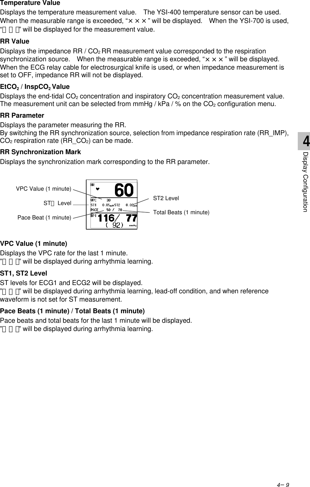
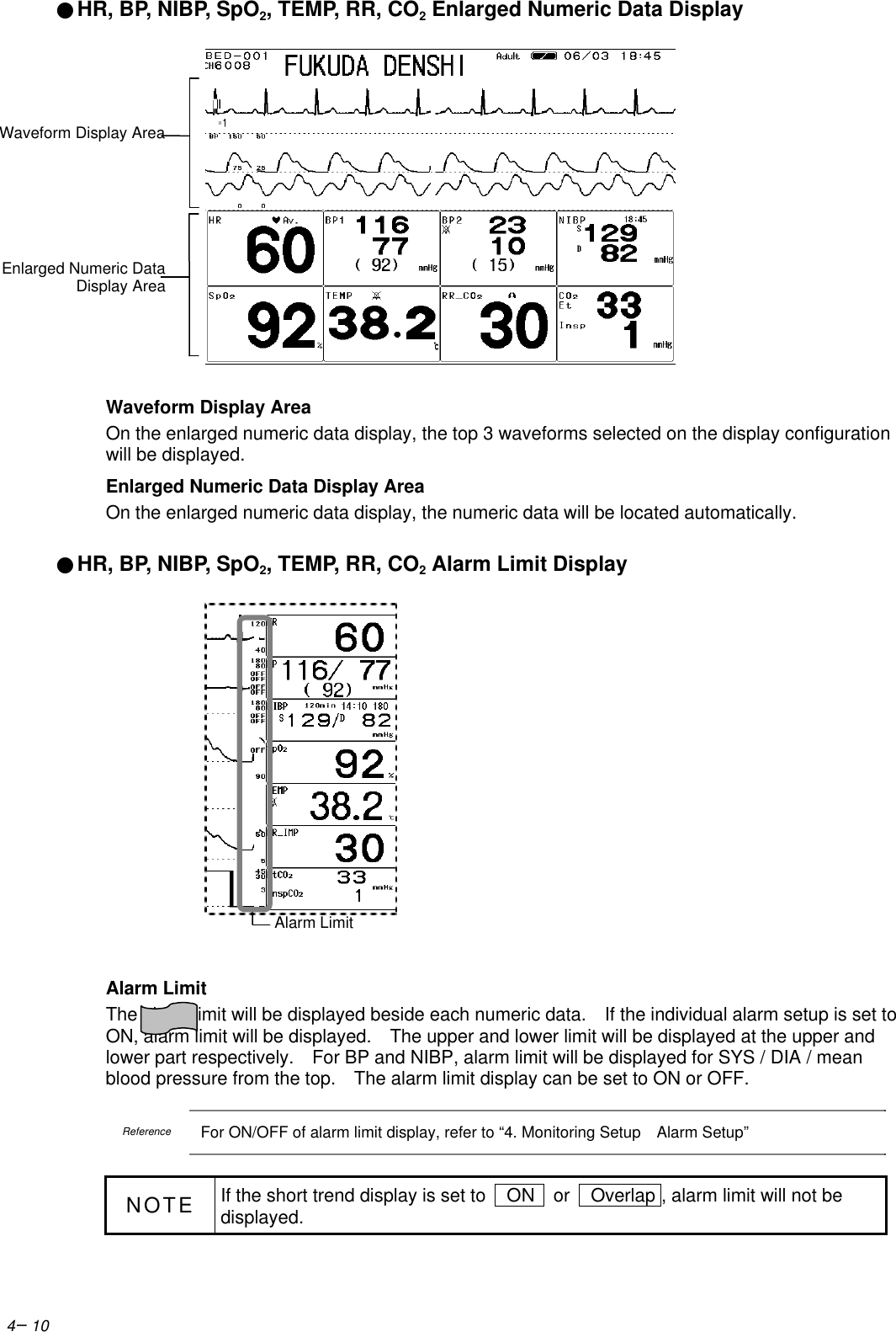
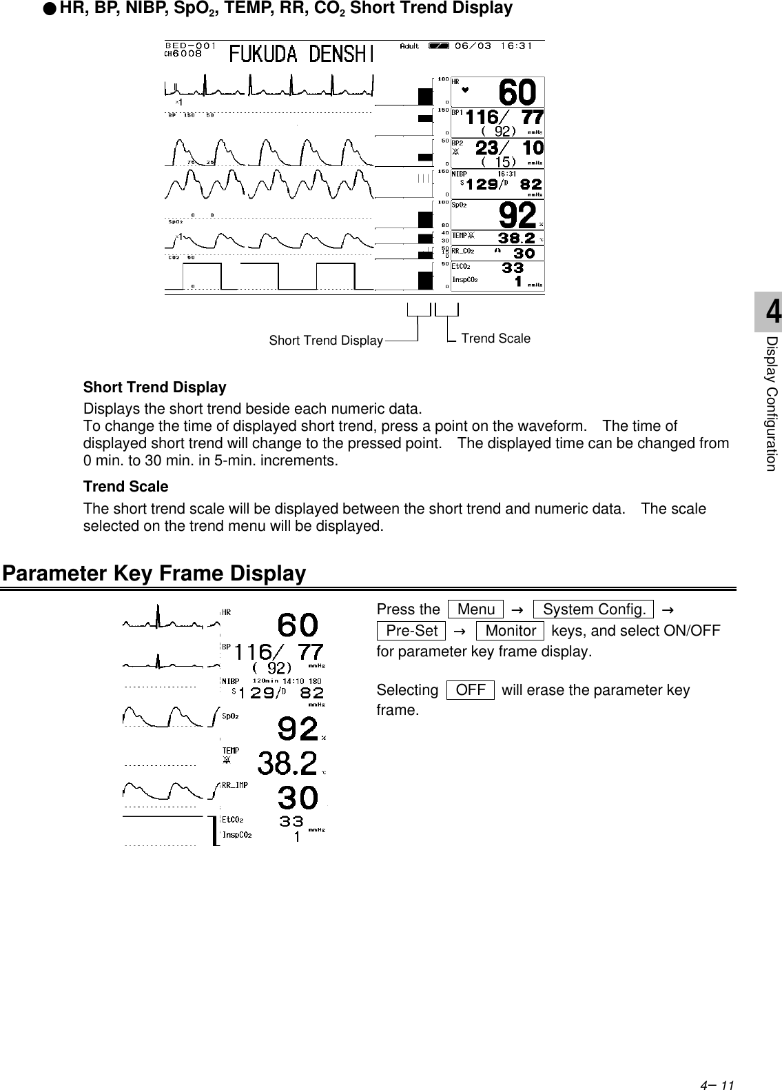
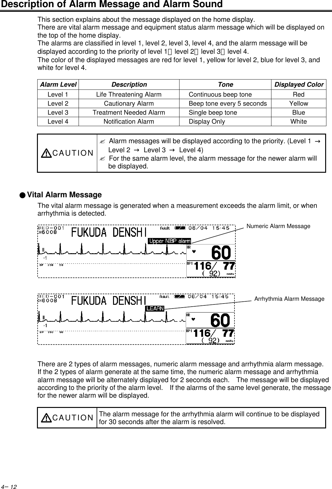
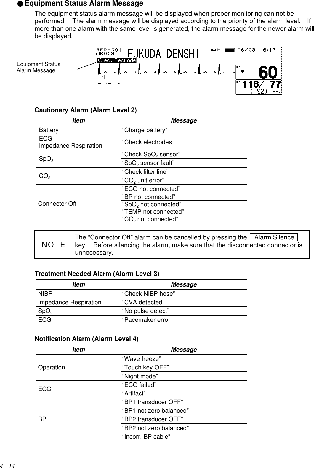
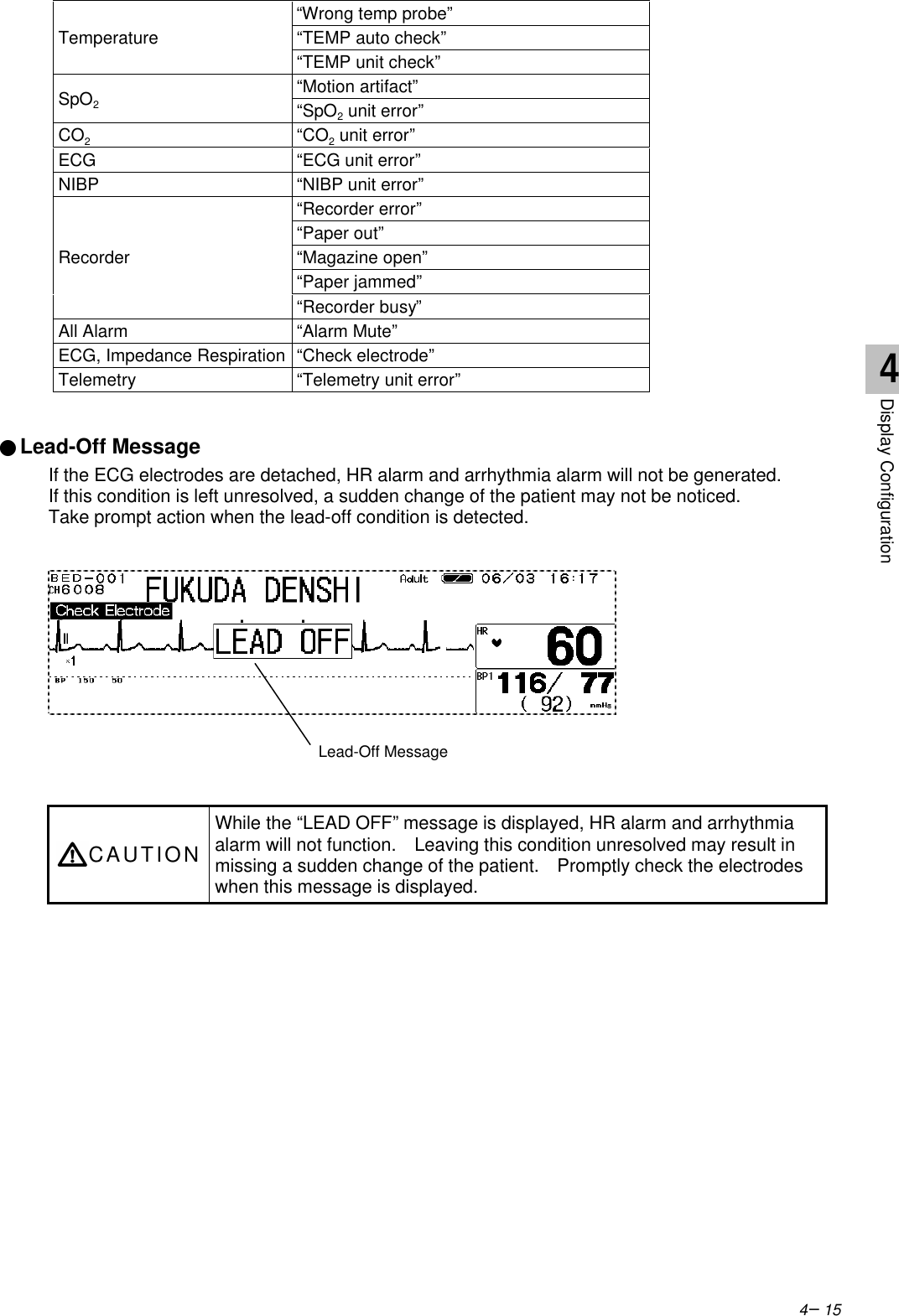
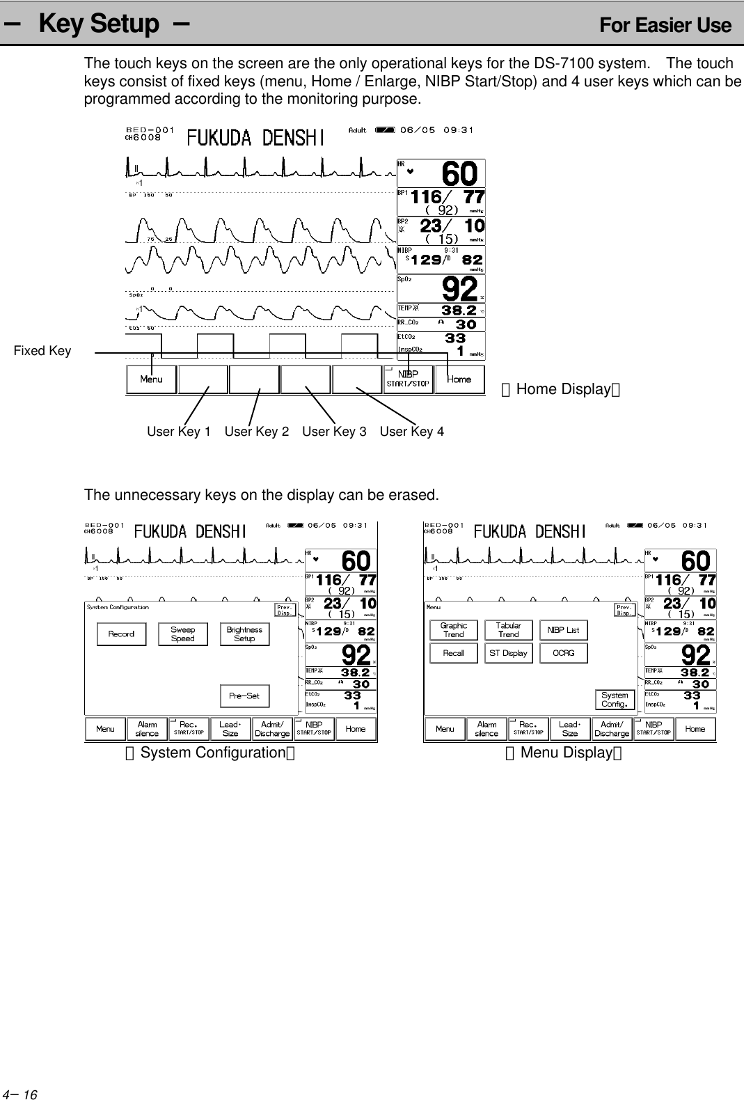
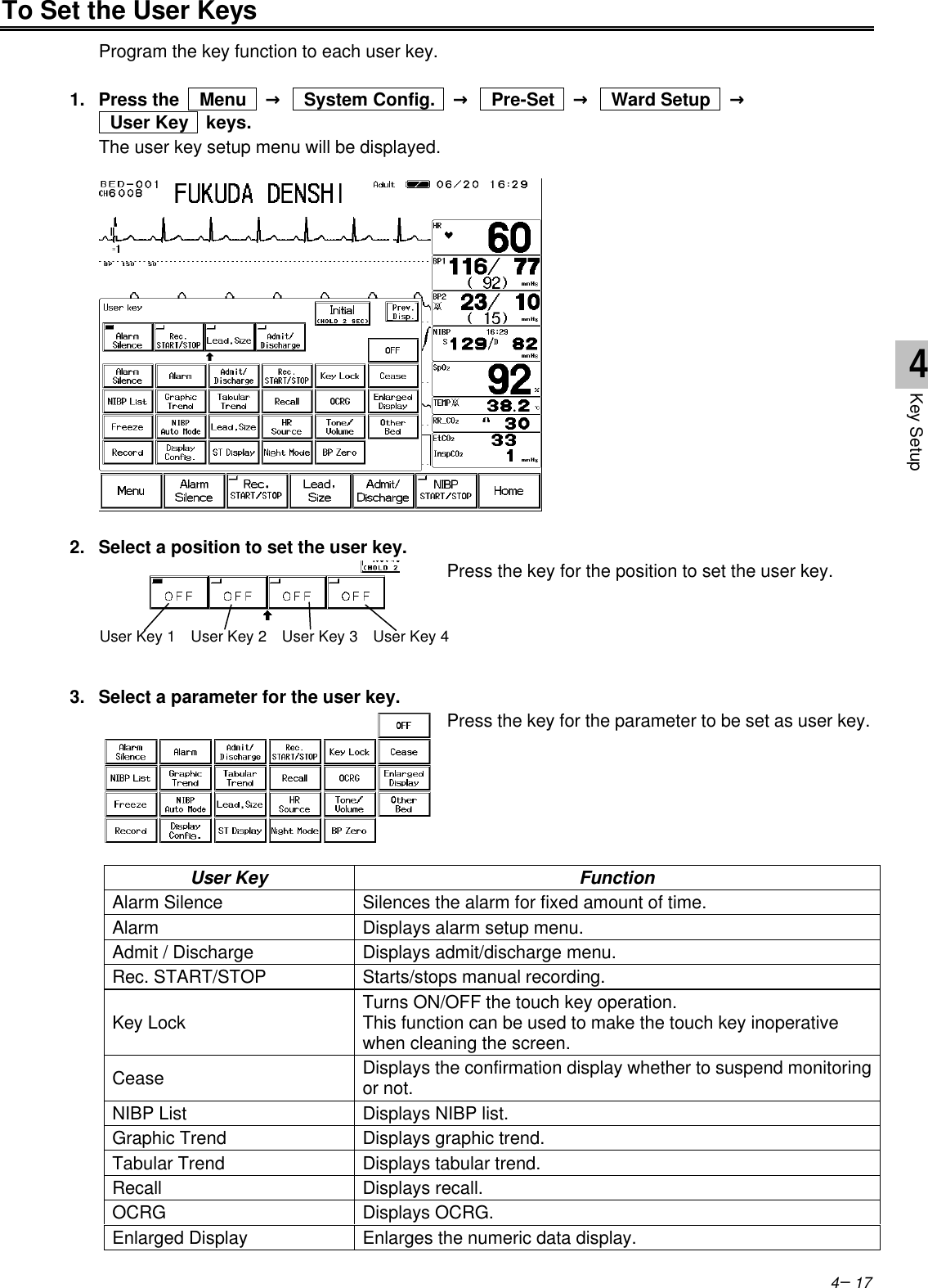
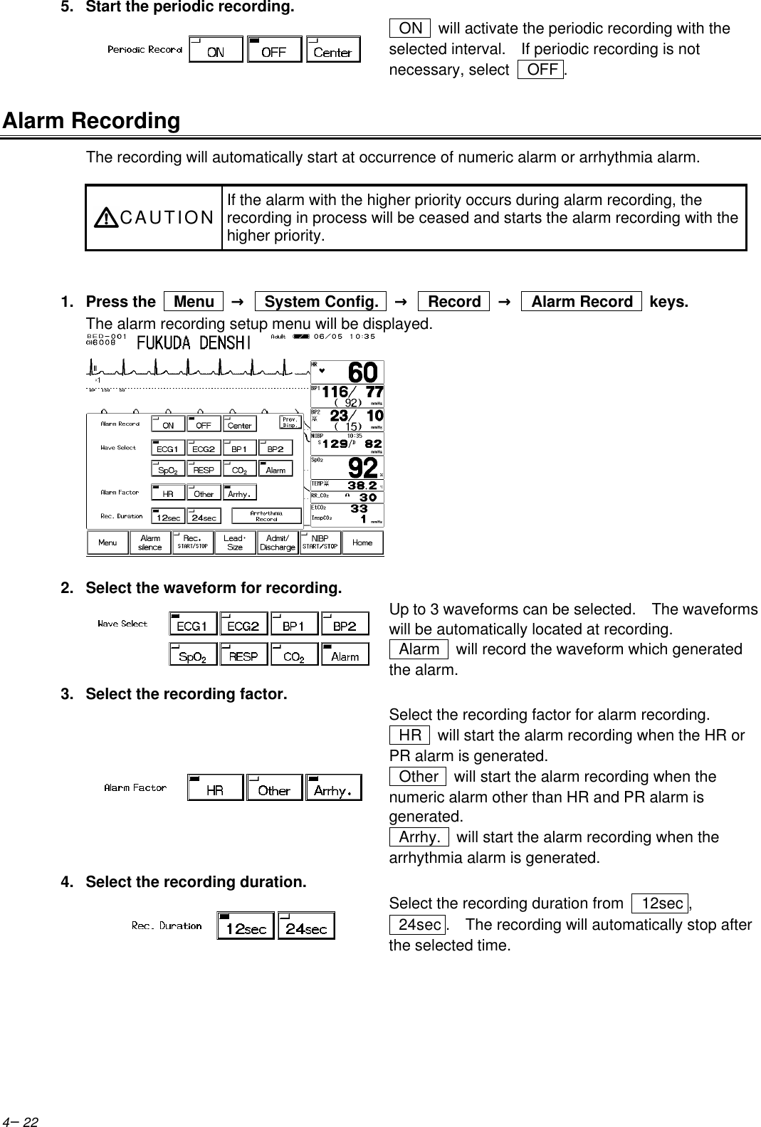

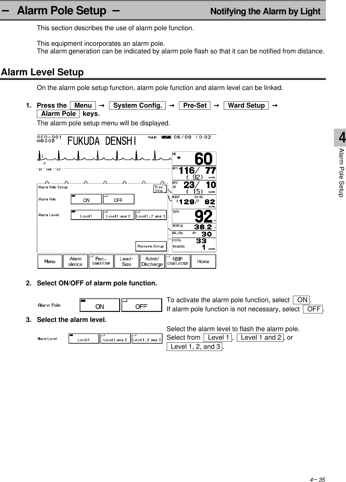
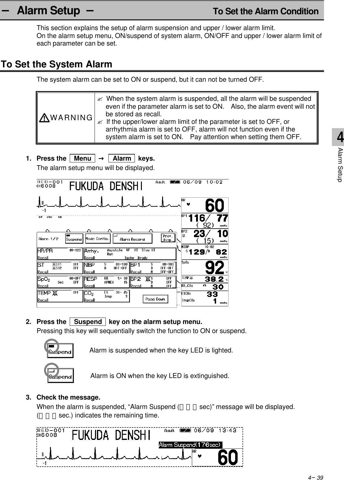
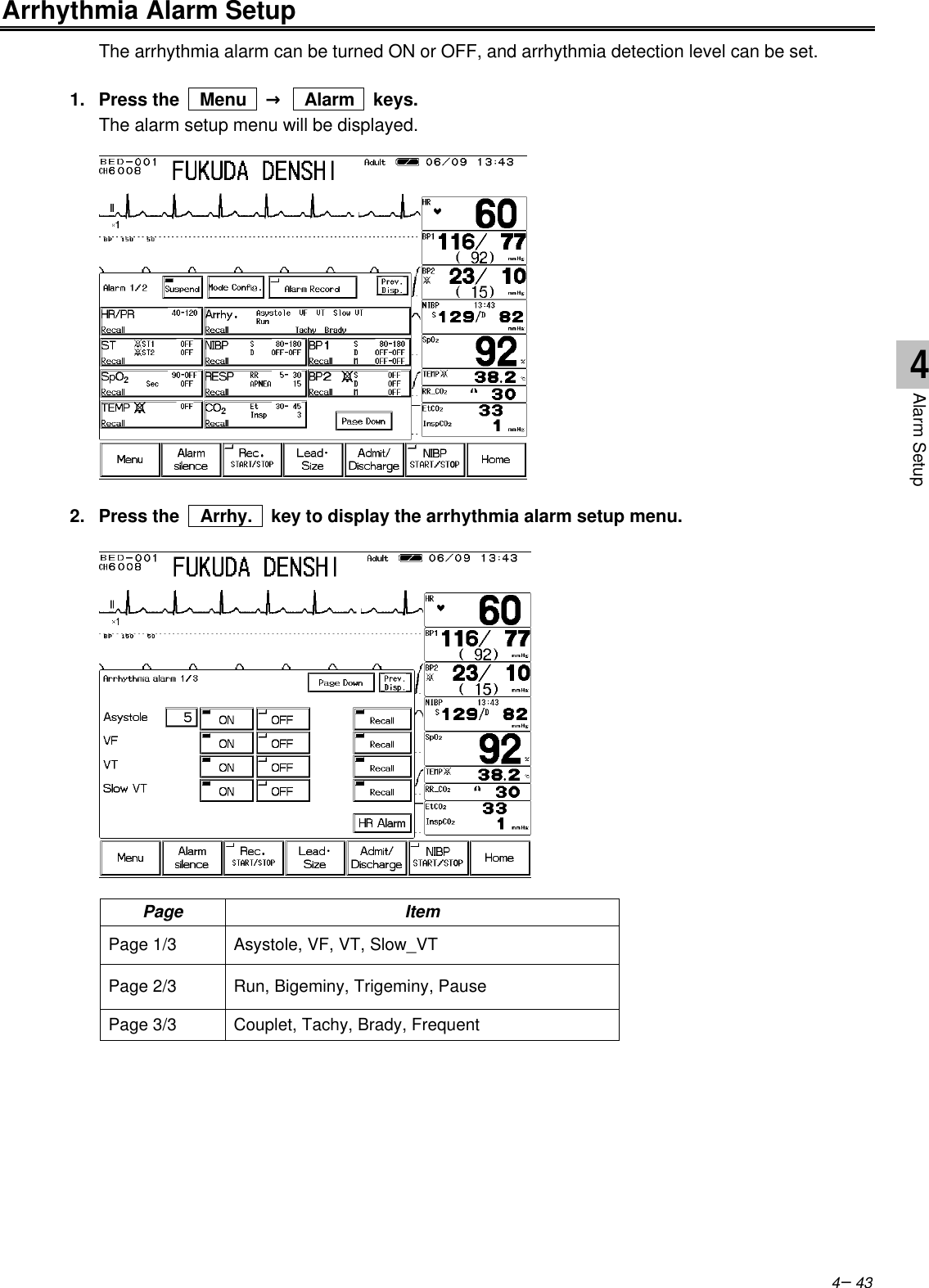
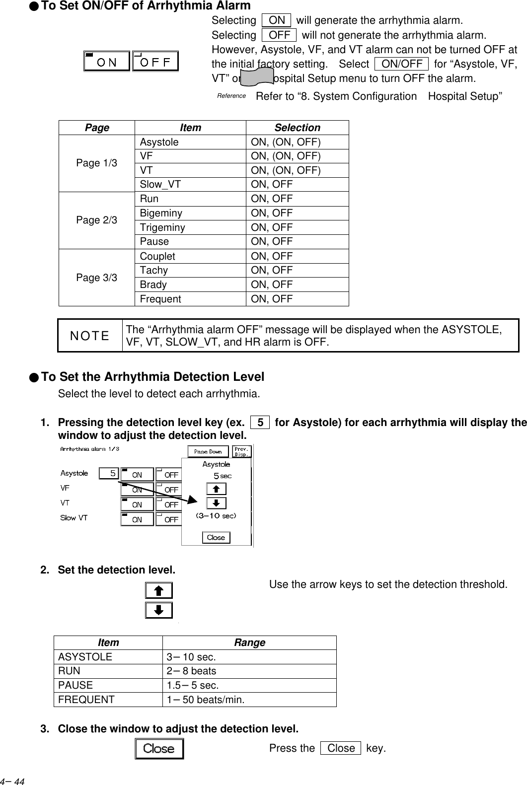
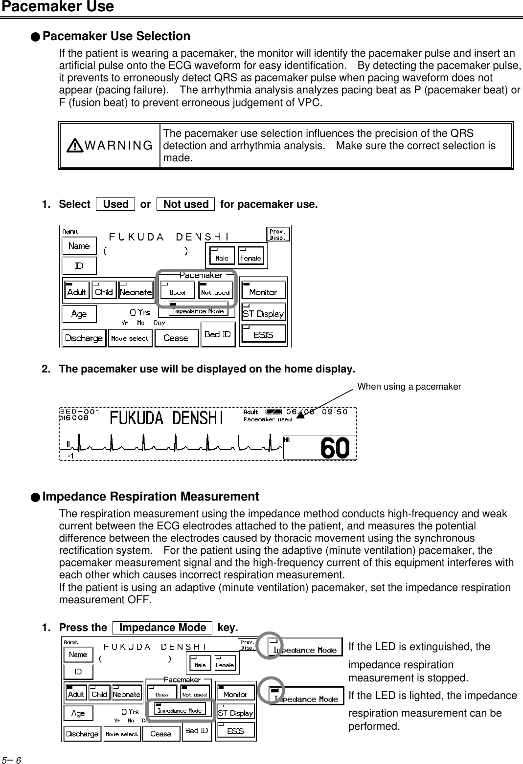
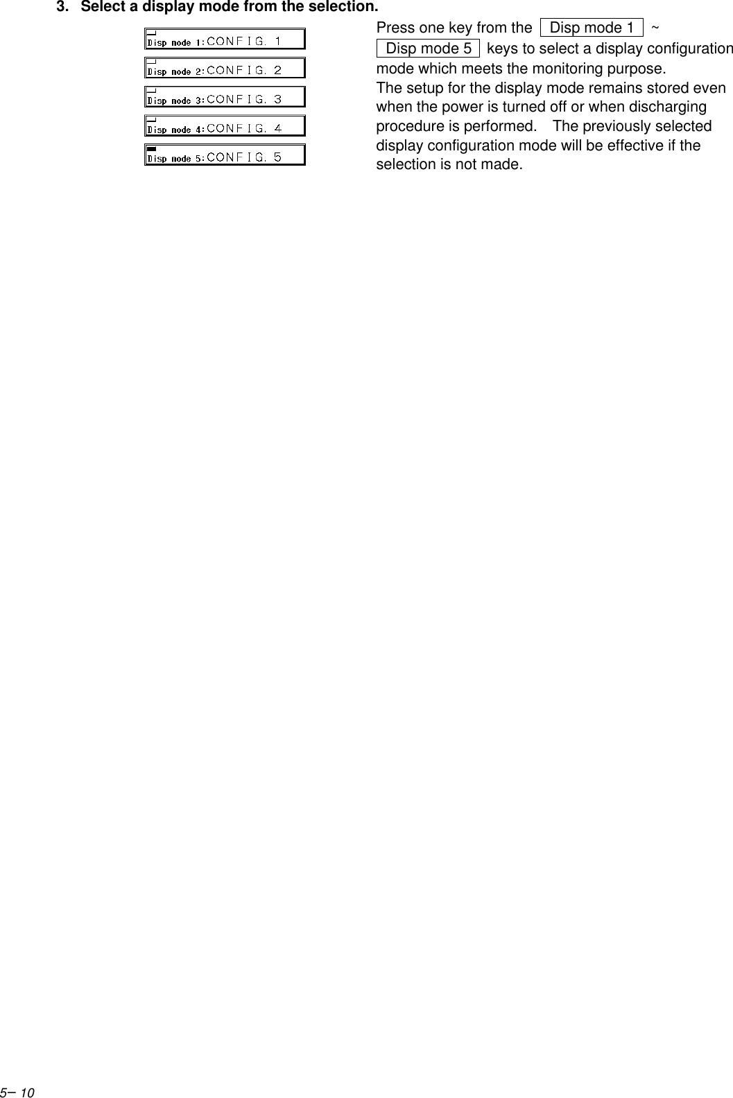
![4−45●Alarm Limit for TACHY, BRADYThe arrhythmia detection level for tachycardia (TACHY) and bradycardia (BRADY) alarm links withthe upper and lower alarm limit for HR / PR.The tachycardia (TACHY) alarm generates when the measurement exceeds the HR / PR upperalarm limit. When the upper alarm limit is OFF, alarm will not generate.The bradycardia (BRADY) alarm generates when the measurement is below the HR / PR loweralarm limit. When the lower alarm limit is OFF, alarm will not generate.SpO2 SEC Alarm SetupWhen the SpO2 value is unstable around the lower alarm limit, the frequently generated alarm maybe bothersome. The SEC alarm function controls these frequent alarms.This function generates the alarm only when the integral value (the accumulation of differencebetween the alarm limit and SpO2 value at every second) reaches the preprogrammed SEC alarmthreshold value.01020304050607080901001 5 9 13 17 21 25 29 33 37 41 45 49 53 57 61[SEC]SEC Alarm Integral Value [%]Integral ValueAlarm GenerationSpO2 ValueAlarm LimitOn this graph, the SEC alarm threshold value is set as 100.The SpO2 value begins to fall below the alarm limit at approximately 10 seconds. At the sametime, the integral value begins to increase.(Alarm limit) – (SpO2 value) is accumulated each second.At around 25 seconds, the integral value reaches 100 and the alarm is generated.At approximately 36 seconds, the SpO2 value returns to the level within the alarm limit, and at thesame time, the integral value begins to decrease. {(Alarm limit) – (SpO2 value)}× 2 is subtractedeach second.Also, there is a safety net when setting the SEC alarm function. This safety net is for the casewhen the SpO2 value frequently falls below the alarm limit but does not last long enough to reachthe SEC alarm threshold.If the SpO2 value falls below the limit 3 times or more during the last 60 seconds, an alarm will begenerated even if the SEC alarm threshold is not reached.4Alarm Setup](https://usermanual.wiki/Fukuda-Denshi-Co/DS7100.Manual-6/User-Guide-380408-Page-45.png)