Fujitsu Technology Solutions SCENIC6651 Personal Computer User Manual A26361 K520 Z200 1 7619

Fujitsu Technology Solutions GmbH Personal Computer A26361 K520 Z200 1 7619

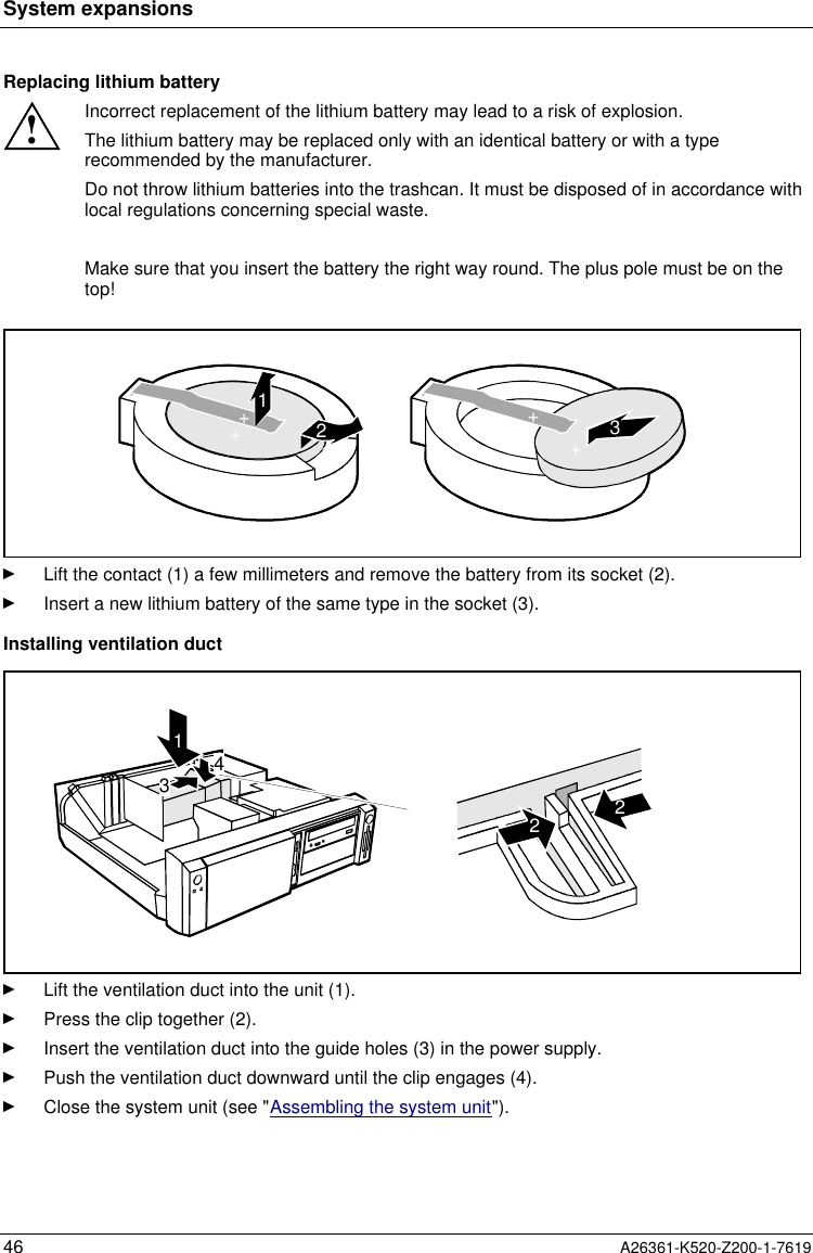
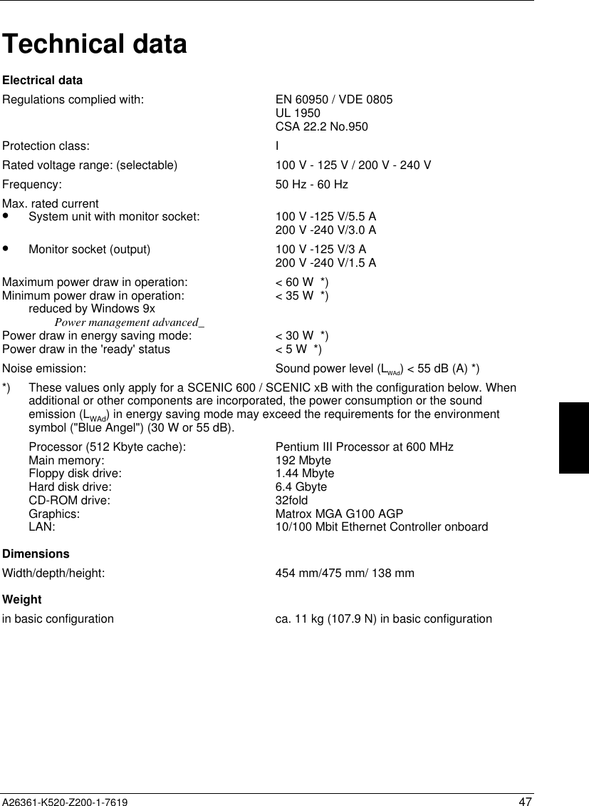
Scenic 600 Scenic xB May 2000 part4

System expansions34 A26361-K520-Z200-1-76191a32Ê  Push the board up to its slot (1).Ensure that the end of a long board without angle bracket fits into the corresponding guide ofthe system unit. Ensure also that the point of the angle bracket slots into guide (a).Ê  Press the board into the slot so that it engages.Ê  Replace the clip (2) which fixes the board. Make sure that the clip engages when released (3).Ê  If necessary, plug the lines on the board.Ê  Close the system unit (see "Assembling the system unit").Removing a boardÊ  Open the system unit (see "Opening the system unit").Ê  Remove the lines connected to the board.312Ê  Press on the clip in the direction of the arrow (1) and remove it (2).Ê  Remove the board from the system unit (3).Ê  Place the board into an appropriate packaging.!For cooling, protection against fire and in order to comply with EMC (electromagneticcompatibility) regulations, you must refit the rear slot cover plate.
System expansionsA26361-K520-Z200-1-7619 35132aÊ  Push the rear slot cover plate into the slot (1). Ensure that the point of the cover engages intothe guide (a).Ê  Replace the clip (2) which fixes the board. Make sure that the clip engages when released (3).Ê  Close the system unit (see "Assembling the system unit").iIf you have installed or removed a PCI board, please check in the BIOS Setup the settingsfor the relevant PCI slot. If necessary, change the settings. Further information is providedin the documentation for the PCI board.Installing and removing drivesThe system unit houses a total of three accessible drives (two 5 1/4-inch drives and one 3 1/2-inchdrive) and two non-accessible half-height (Slimline) drives .IDE drivesBy default four IDE drives are supported. Ideally hard disks are connected to IDE port 1, andaccessible IDE drives, for example CD-ROMs, to IDE port 2 (see also the Technical Manual for thesystem board).SCSI drivesIf you want to install an SCSI drive, you require an SCSI controller and an SCSI cable. Note that:•  not every SCSI controller is suitable for operating SCSI hard disks•  each SCSI device must be assigned its own SCSI-ID.•  the SCSI cable must always be terminated at the end, either by a drive or by a terminatingresistor on the cable. The terminating resistors of all other SCSI devices attached must not beactivated or connected.•  depending on the SCSI technology (UW, U2W), an adapter may be required for connecting theSCSI drives with a 50-pin connector.
System expansions36 A26361-K520-Z200-1-7619Installing an accessible driveÊ  Open the system unit (see "Opening the system unit").iShould the chipcard reader get in the way of the accessible drive during installation, thenremove the reader (see "Installing/removing a chipcard reader").AB12Ê  Pry the plastic drive cover (A) out of the front cover.Ê  Pry the shielding plate (B) on left-hand side out of the bay.!Do not throw away the covers. If you remove the drive again later, you will have toreinstall the covers.Ê  Take the new drive out of its packaging.Ê  Make the required settings on the drive (if necessary, on installed drives as well).21ABA = Position of the screw for the upper driveB = Position of the screw for the lower driveÊ  Slide the drive into the system unit (1).Ê  Plug the data and the power supply connectors into the drive.Ê  Fasten the drive with the screw (2).Ê  If you have removed the chipcard reader, then reinstall it.
System expansionsA26361-K520-Z200-1-7619 37Ê  Close the system unit (see "Assembling the system unit").iIf necessary, you must adapt the entry for the drive in the Setup menu.Installing a hard disk drive in the front bayÊ  Open the system unit (see "Opening the system unit").Ê  Make the required settings (e. g. master-slave) on the hard disk drives.Ê  Fasten the drive with the four screws (2).Ê  Install the installation frame with the drive in the desired front bay (see "Installing an accessibledrive").Ê  Close the slot with the panel. Ensure that the cover engages.Ê  Close the system unit (see "Assembling the system unit").
System expansions38 A26361-K520-Z200-1-7619Removing an accessible driveÊ  Open the system unit (see "Opening the system unit").Ê  Pull the data and the power supply connectors from the desired drive.iShould the chipcard reader get in the way of the accessible drive during installation, thenremove the reader (see "Installing/removing a chipcard reader").12ABA = Position of the screw for the upper driveB = Position of the screw for the lower driveÊ  Remove the relevant screw (1) and take the drive out of the system unit (2).ABÊ  Insert the shielding plate (B) on the right-hand side on the installation bay and press it in.Ê  Press the plastic drive cover (A) into the front panel until it snaps in place.Ê  If you have removed the chipcard reader, then reinstall it.Ê  Close the system unit (see "Assembling the system unit").iIf necessary, you must adapt the entry for the drive in the Setup menu.
System expansionsA26361-K520-Z200-1-7619 39Changing the floppy disk driveÊ  Open the system unit (see "Opening the system unit").Ê  Remove the hard disk carrier (see "Installing and removing the hard disk drive").12Ê  Pull the data and the power supplyconnectors from the floppy disk drive.Ê  Remove the screw (1) and take the driveout of the system unit (2).Ê  Take the new floppy disk drive out of itspackaging.21Ê  Push the drive into the system unit (1), andfix it with the screw (2).Ê  Plug the data and the power supplyconnectors into the floppy disk drive.Ê  Remove the hard disk carrier (see"Installing and removing the hard diskdrive").Ê  Close the system unit (see "Assemblingthe system unit").iIf necessary, you must adapt the entry for the drive in the Setup menu.
System expansions40 A26361-K520-Z200-1-7619Installing and removing the hard disk driveÊ  Open the system unit (see "Opening the system unit").Removing the hard disk carrier2134Ê  Lift the hard disk carrier out of the mounting in the direction of the arrow (1) and (2).Ê  Lift the hard disk carrier out of the system unit in the direction of the arrow (3) and (4).Ê  Pull the data and power supply connectors from the hard disk drive or the hard disk drives.Installing the first hard disk driveÊ  Take the new hard disk drive out of its packaging.Ê  Make the required settings (e. g. master/slave, stand alone) on the drives.2213Ê  Insert the hard disk drive into the plastic bracket (1). The drive must engage in the plasticnipple.Ê  Fold the plastic bracket in the direction of the arrow (2) on the hard disk drive.Ê  Push the hard disk drive into the drive carrier until the plastic bracket engages (3).
System expansionsA26361-K520-Z200-1-7619 41Installing the second hard disk drive2221Ê  Take the new hard disk drive out of itspackaging.Ê  Make the required settings (e. g.master/slave, stand alone) on the drives.Ê  Slide the hard disk drive into the drivecarrier (1).Ê  Fasten the drive with the screws (2).Removing the first hard disk drive12Ê  Lightly press on the clip (1).Ê  Pull the hard disk drive out of the carrier(2).112Ê  Fold the plastic bracket in the direction ofthe arrow (1).Ê  Remove the hard disk drive (2).
System expansions42 A26361-K520-Z200-1-7619Removing the second hard disk drive2111Ê  Remove the screw (1).Ê  Pull the hard disk drive out of the carrier(2).Ê  Make the required settings on theremaining hard disk drive (e.g. standalone).Installing the hard disk carrier3421Ê  Plug the data and the power supply connectors into the hard disk drive or into the hard diskdrives.Ê  Lift the hard disk carrier into the system unit in the direction shown by the arrow (1) and push itforward until it engages (2).Ê  Press the hard disk carrier in the direction of the arrow (3) and press it downward (4).Ê  Close the system unit (see "Assembling the system unit").iIf necessary, you must adapt the entry for the drive in the Setup menu.
System expansionsA26361-K520-Z200-1-7619 43Installing/removing a chipcard readerÊ  Open the system unit (see "Opening the system unit").Installing a chipcard readerÊ  Remove the protector panel at the front of the carrier.Ê  Push the chipcard reader board into the guide rail of the carrier with the component's sidetoward the panel.Ê  Fix the board with the screw.312Ê  Fix the cable on the chipcard reader (1) and on the connector for the chipcard reader on thesystem board (see the Technical Manual of the system board).Ê  Lift the chipcard reader into the system unit (2).Ê  Push the chipcard reader in the direction of the arrow (3) until it clicks into position. Pressdownward and toward the drive cage while doing so.iWith the chipcard reader connected, no devices may be connected to serial port 2.Removing a chipcard reader2314Ê  Pull the cable off the chipcard reader (1) and off the connector for the chipcard reader on thesystem board (see the Technical Manual of the system board).
System expansions44 A26361-K520-Z200-1-7619Ê  Press on the clip (2).Ê  Pull the chipcard reader in the direction of the arrow (3).Ê  Lift the chipcard reader out of the system unit (4).Installation opening for 2nd serial portAn installation opening for the 2nd serial port is provided on the back of the casing. As a result, thismeans no board slot is occupied.Ê  Insert a screwdriver into the opening and break out the pre-stamped installation opening bymoving back and forth.Extensions on the system boardDetails of how and if you can upgrade the main memory or the processor of your PC are provided inthe Technical Manual for the system board. Below the necessary steps are described to enable youto work on the system board.Open the system unit (see "Opening the system unit").Upgrading main memoryÊ  Upgrade the memory as it is described in the Technical Manual for the system board.Ê  Close the system unit (see "Assembling the system unit").
System expansionsA26361-K520-Z200-1-7619 45Replacing processor and lithium batteryTo replace the processor and the lithium battery, you must remove the ventilation duct.Removing ventilation duct23411Ê  Press the clip together (1).Ê  Lift the ventilation duct slightly (2) and guide the ventilation duct out of the guide holes (3).Ê  Remove the ventilation duct from the unit (4).You have free access to the locations.Replacing processorÊ  Make the desired expansions (see the Technical Manual for the system board).
System expansions46 A26361-K520-Z200-1-7619Replacing lithium battery!Incorrect replacement of the lithium battery may lead to a risk of explosion.The lithium battery may be replaced only with an identical battery or with a typerecommended by the manufacturer.Do not throw lithium batteries into the trashcan. It must be disposed of in accordance withlocal regulations concerning special waste.Make sure that you insert the battery the right way round. The plus pole must be on thetop!123++++Ê  Lift the contact (1) a few millimeters and remove the battery from its socket (2).Ê  Insert a new lithium battery of the same type in the socket (3).Installing ventilation duct43122Ê  Lift the ventilation duct into the unit (1).Ê  Press the clip together (2).Ê  Insert the ventilation duct into the guide holes (3) in the power supply.Ê  Push the ventilation duct downward until the clip engages (4).Ê  Close the system unit (see "Assembling the system unit").
A26361-K520-Z200-1-7619 47Technical dataElectrical dataRegulations complied with: EN 60950 / VDE 0805UL 1950CSA 22.2 No.950Protection class: IRated voltage range: (selectable) 100V-125V/200V-240VFrequency: 50 Hz - 60 HzMax. rated current•  System unit with monitor socket:•  Monitor socket (output)100 V -125 V/5.5 A200 V -240 V/3.0 A100 V -125 V/3 A200 V -240 V/1.5 AMaximum power draw in operation:Minimum power draw in operation:reduced by Windows 9xPower management advanced_Power draw in energy saving mode:Power draw in the 'ready' status<60W *)<35W *)<30W *)<5W *)Noise emission: Sound power level (LWAd)<55dB(A)*)*) These values only apply for a SCENIC 600 / SCENIC xB with the configuration below. Whenadditional or other components are incorporated, the power consumption or the soundemission (LWAd) in energy saving mode may exceed the requirements for the environmentsymbol ("Blue Angel") (30 W or 55 dB).Processor (512 Kbyte cache):Main memory:Floppy disk drive:Hard disk drive:CD-ROM drive:Graphics:LAN:Pentium III Processor at 600 MHz192 Mbyte1.44 Mbyte6.4 Gbyte32foldMatrox MGA G100 AGP10/100 Mbit Ethernet Controller onboardDimensionsWidth/depth/height: 454 mm/475 mm/ 138 mmWeightin basic configuration ca. 11 kg (107.9 N) in basic configuration
Technical data48 A26361-K520-Z200-1-7619Environmental conditionsEnvironment class (3K2)Environment class (2K2) DIN IEC 721 part 3-3DIN IEC 721 part 3-2Temperature:•  Operating (3K2)•  Transport (2K2) 15 °C .... 35 °C-25 °C .... 60 °CCondensation in operating must be avoided.Clearance required to ensure adequate ventilation:•  left-hand side•  front•  rearmin. 200 mmmin. 200 mmmin. 200 mm!Do not place several system units one above the other.
A26361-K520-Z200-1-7619 49Index22nd serial port, installation opening 44AAccessible driveinstalling 36removing 38Accumulator, disposal 5Activating, security measures 23Alphanumeric keypad 20Alt Gr key 21Anti-theft protection 24Audio input 11Audio output 11BBattery 46disposal 5BIOS Setup 23security functions 24Board 3installing 33removing 33CCableconnecting 10disconnecting 10Cabling, PC 10Calculator keypad 20Casinglock 15opening 31CD-ROM driveindicator 19installing 36manual 29removing 38CE certificate 5Changingfloppy disk drive 39hard disk drive 40lithium battery 46Checking, rated voltage 14Chipcard reader 11indicator 20Class B Compliance Statement 5Cleaning 8
Index50 A26361-K520-Z200-1-7619Clearance 48Configuration, BIOS-Setup 23Connectingcables 10devices 10keyboard 12monitor 13mouse 12parallel port 12power voltage 14serial port 12Connecting to power voltage 14Contents of delivery 9Control key 21Courier 1Ctrl key 21Ctrl+Alt+Del 21Cursor control keys 20DDark screen 26Dataprotection 23technical 47Date, not correct 28Devicesconnecting 10interface 11Dimensions 47Diskette 22write-protection 22Display, cleaning 8Disposal 4Drive 35cover 15hard disk drive, installing 37EEarphone 11Electrical data 47Electromagnetic compatibility 5Energy saving 4Enter key 21Environmental conditions 48Environmental data 48Ergonomic, video workstation 10Errordate 28floppy 27mouse 27screen 26system unit 25time 28Error message 28
IndexA26361-K520-Z200-1-7619 51ESD 3Euro key 21Expansion 31External devicesconnecting 10ports 11FFCC statement 5First time, switching on 17Flashing power-on indicator 19Floppy disk drivechanging 39indicator 20removing 38Floppy disk, cannot be read or written 27Function keys 20GGame port 11Green, power-on indicator 19Guarantee coupon booklet 9HHard disk carrierinstalling 42removing 40Hard disk driveinstalling 37replacing 40Hard disk indicator 19IIDE drives 35Important notes 3Indicatorpower-on indicator fails to light 25remains blank 26Indicators, on the PC 19Installation opening, 2nd serial port 44Installingaccessible drive 36board 33hard disk carrier 42hard disk drive 40,41new Software 25ventilation duct 46Insufficient memory 28Interfaces 11Italics 1KKensington Lock 24
Index52 A26361-K520-Z200-1-7619Key combination 21Keyboard 20cleaning 8connecting 12port 11Keys 21LLAN port 11Lead-sealing 24Line in 11Line out 11Lithium battery 44replacing 46Lock 15Locking, PC 15MMain memory 44Main switch 16Manuals, further 29Manufacturer’s notes 4Memory, upgrading 44Menu key 21Message indicator 19Microphone jack 11Monitorconnecting 13port 11transporting 7Mousecleaning 8connecting 12error 27port 11NNew Installation, Software 25No screen display 26Noise level 47Not enough memory 28Notational conventions 1Noteboards 3CE certificate 5disposal 4energy saving 4important 3manufacturer 4power cord selection 6safety 3Num Lock key 21Numeric keypad 20
IndexA26361-K520-Z200-1-7619 53OON/OFF switch 16,21Opening, system unit 31Operation 9Orange, power-on indicator 19Other manuals 29OverviewPC 1preparing for use 9PPacking material 9Parallel port 11connecting devices 12PC cabling 10cannot boot 25cleaning 8connecting 10connecting to power voltage 14indicators 19locking 15opening 31ports 11setting up 10switching off 16,18switching on 16,18switching on for the first time 17transporting 7unlocking 15Ports, external devices 11Power cord selection 6Power management 28Power-on indicator 16,19dark 25POWERSAV.SCR 4Preparation for use 9Preparing for use, overview 9Printer 11Problems 25Processor 44replacing 45Property protection 23PS/2 mouse port 11QQuiet Boot 26RRated voltage, setting 14Ready-to-operate 16Recycling 4Reinstalling, hard disk contents 28Removing
Index54 A26361-K520-Z200-1-7619accessible drive 38board 33hard disk carrier 40hard disk drive 41,42ventilation duct 45Replacingboard 33hard disk drive 40lithium battery 46Restoring, hard disk contents 28Return key 21SSafety 3Screen blank 17,18,26Screen blanking 4SCSI drives 35SCSI port 11Security function 24casing lock 23chipcard 23MS-Windows 23Security measures 23Select, power cord 6Serial port 11connecting devices 12Setting rated voltage 14Settings, BIOS Setup 23Setup, see BIOS SetupShift key 21Soft Power Off 18Software, New Installation 25Start key 21Streamerinstalling 36removing 38Summer time 28Surface 47Switching off, PC 16,18Switching on, PC 16,18Symbols, explanation of 1System board, extensions 44System expansion 31System settings, BIOS Setup 23System unit, see PCTTechnical data 47Time, not correct 28Tips 25,28Transport 7Troublefloppy disk 27mouse 27
IndexA26361-K520-Z200-1-7619 55screen 26system unit 25Troubleshooting 25UUnlocking, PC 15Unpacking 9Upgrading, memory 44USB, Universal Serial Bus 11VVentilation area 48Ventilation ductinstalling 46removing 45VESA (DPMS) 4Video workstation 10WWarm boot 21Weight 47Winter time 28Write protection, floppy 22

Navigation menu