Fujitsu Technology Solutions SCENIC6651 Personal Computer User Manual A26361 K520 Z200 1 7619
Fujitsu Technology Solutions GmbH Personal Computer A26361 K520 Z200 1 7619
Contents
- 1. Manual Scenic 600 Oct 99 part 1
- 2. Manual Scenic 600 Oct 99 part 2
- 3. Manual Scenic 600 Oct 99 part 3
- 4. Manual Scenic 600 Oct 99 part 4
- 5. Manual Scenic 600 Oct 99 part 5
- 6. Manual Scenic 600 Oct 99 part 6
- 7. Manual Scenic 600 Oct 99 part 7
- 8. Scenic 600 Scenic xB May 2000 part1
- 9. Scenic 600 Scenic xB May 2000 part2
- 10. Scenic 600 Scenic xB May 2000 part3
- 11. Scenic 600 Scenic xB May 2000 part4
Scenic 600 Scenic xB May 2000 part3
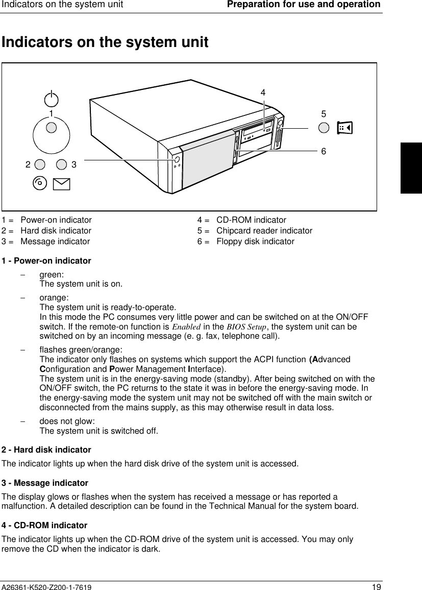
![Switching the PC on and off Preparation for use and operationA26361-K520-Z200-1-7619 17Switching on the PC for the first timeIf the PC is integrated into a network, the user and server details as well as the network protocol arerequired. Contact your network administrator if you have any questions about these details.When you switch on your PC for the first time the supplied software is set up and configured.If you require the license number of Windows, you will find it either on a sticker on your PC orprinted on the front cover of the Windows manual provided.Ê Switch your monitor on.Ê Switch the system unit on with the ON/OFF switch.The power-on indicator lights green and the PC is started.iWhile the PC boots, the screen remains dark for up to a minute depending on the systemconfiguration. To see the start-up messages, you can switch off this standard setting inthe BIOS Setup in the Quiet Boot entry.Ê Adjust the brightness if necessary (see the Operating Manual for the monitor).iSome variants require you to start the software installation by pressing the function key[F1][F1][F1][F1].Once the installation has been started the PC must not be switched off.You should only reboot the PC during installation if you are requested to do so. Otherwisethe installation will be not be performed correctly. If a fault occurs in the installation thecontents of the hard disk must be completely restored.Ê During installation follow the instructions on the screen.Consult the operating system manual if there is anything unclear about the requested input data.Some system configurations do not include a Windows CD in the delivery package. In this case youshould create a backup copy after installing Windows so that you can restore the hard disk contentsin an emergency.You need about 40 diskettes for this.Ê Create Windows diskettes with the MSCSD backup program (create system diskettes) and labelthem using the labels supplied.iYou will find further information about the system, drivers, utilities, updates, and manualsetc. on the "Drivers & Utilities" CD supplied.](https://usermanual.wiki/Fujitsu-Technology-Solutions/SCENIC6651.Scenic-600-Scenic-xB-May-2000-part3/User-Guide-100416-Page-3.png)
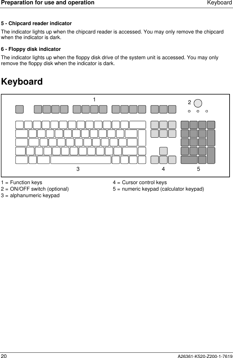
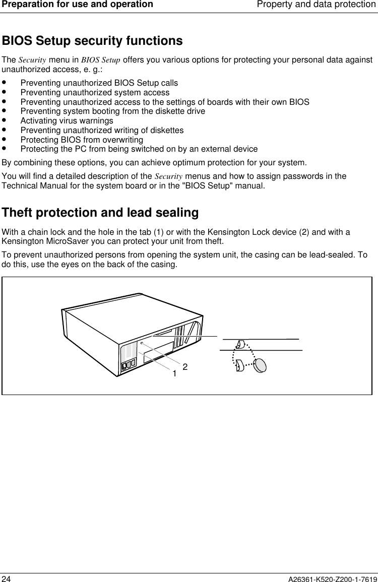
![Keyboard Preparation for use and operationA26361-K520-Z200-1-7619 21Important keys and key combinationsThe following description of keys and key combinations refers to MS Windows. Details of other keysand key combinations can be found in the documentation of the relevant application program.ON/OFF switchDepending on the setting in the BIOS setup, the system can be switched on, off or onand off with this switch.Enter keyconfirms or starts the marked selection. The enter key is also referred to as the"Return" key or "Carriage Return".Start keyinvokes the START menu of Windows.Menu keyinvokes the menu for the marked item.Shift keyenables upper-case letters and the upper key symbols to be displayed.Alt Gr Alt Gr (e.g. German keyboard)produces a character shown on the right-hand side of a key (e. g. the character "\"on the key [ß][ß][ß][ß]).%5$4Euro keyenables the output of the euro symbol.Num Num Lock keyby pressing the Num Lock key you switch between the upper- and lower-case levelsof the calculator keypad.At upper-case level (Num Lock indicator lit) the digit and comma keys are active.At lower-case level (Num Lock indicator not lit) the cursor control functions areactive in the calculator keypad.Ctrl Ctrl keystarts key combination actions.Ctrl Alt DelWarm bootrestarts your PC. First hold down the [Ctrl][Ctrl][Ctrl][Ctrl] and [Alt][Alt][Alt][Alt] key, andthen press the [Del][Del][Del][Del] key. With Windows 9x the Task Managerappears first. The warm start is then carried out the secondtime.](https://usermanual.wiki/Fujitsu-Technology-Solutions/SCENIC6651.Scenic-600-Scenic-xB-May-2000-part3/User-Guide-100416-Page-7.png)
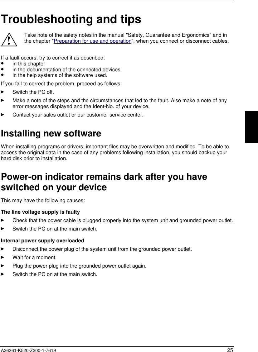
![Troubleshooting and tips26 A26361-K520-Z200-1-7619The screen stays blankIf your screen remains blank this may have the following causes:Monitor is switched offÊ Switch your monitor on.The PC startsWhile the PC boots, the screen remains dark for up to a minute depending on the systemconfiguration. To see the start-up messages, you can switch off this standard setting in the BIOSSetup in the Quiet Boot entry.Screen has been blankedÊ Press any key on the keyboard.orÊ Deactivate screen blanking (screen saver). Enter the appropriate password.Brightness control is set to darkÊ Set the brightness control to bright. For detailed information, please refer to the OperatingManual supplied with your monitor.Power cable or monitor cable not connectedÊ Switch off the monitor and the system unit.Ê Check that the power cable is properly connected to the monitor and system unit or to thegrounded power outlet.Ê Check that the monitor cable is properly connected to the system unit and monitor (if notpermanently attached).Ê Switch on the monitor and the system unit.Wrong monitor has been set under Windows NTÊ Restart the PC in standard VGA mode.Ê Set the desired resolution in the Control Panel window using the Display program, and adjustthe monitor display as described in the Operating Manual.Wrong monitor has been set under Windows 9xÊ Restart the PC.Ê If the message Starting Windows 9x appears, press function key [F8][F8][F8][F8].The Windows 9x start menu appears.Ê Select the option Safe mode or Safe mode with network support .Ê Set the correct values for the attached monitor by selecting Start - Settings - Control Panel -Display - Settings.](https://usermanual.wiki/Fujitsu-Technology-Solutions/SCENIC6651.Scenic-600-Scenic-xB-May-2000-part3/User-Guide-100416-Page-12.png)
![Troubleshooting and tipsA26361-K520-Z200-1-7619 27Wrong monitor has been set under Windows 2000Ê Restart the PC.Ê If the message Starting Windows appears, press function key [F8][F8][F8][F8].The Windows 2000 Advanced Options Menu appears.Ê Select Safe Mode or Safe Mode with Network.Ê Set the correct values for the attached monitor by selecting Start - Settings - Control Panel -Display - Settings.The wrong RAM memory modules have been insertedSee the Technical Manual for the system board for information on which memory modules can beused.No mouse pointer displayed on the screenÊ Shut down the operating system properly.Ê Switch the PC off.Ê Check that the mouse cable is properly connected to the system unit.If you use an adapter or extension lead with the mouse cable, check the connections.Ê Make sure that only one mouse is connected.Ê Switch the PC on.Ê The mouse controller must be enabled, if you use a PS/2 mouse. Check in the BIOS Setup thatthe mouse controller is Enabled.Ê Check that the mouse driver is properly installed and is present when the application programis started. Detailed information can be found in the User Guide of the mouse or applicationprogram.The floppy disk cannot be read or writtenÊ Check that the write protection of the floppy disk or the floppy disk drive is activated (refer alsoto the Technical Manual of the system board or in the manual BIOS).Ê Check the relevant entries for Diskette A: or B: in the Main menu of the BIOS Setup.Ê Check that the floppy disk drive controller is enabled (refer also to the Technical Manual of thesystem board or in the manual "BIOS Setup").Ê Check that the cables of the floppy disk drive are properly connected (refer to chapter "Systemexpansions").](https://usermanual.wiki/Fujitsu-Technology-Solutions/SCENIC6651.Scenic-600-Scenic-xB-May-2000-part3/User-Guide-100416-Page-13.png)