Fujitsu Technology Solutions SCENIC6651 Personal Computer User Manual A26361 K520 Z200 1 7619

Fujitsu Technology Solutions GmbH Personal Computer A26361 K520 Z200 1 7619

Scenic 600 Scenic xB May 2000 part2
A26361-K520-Z200-1-7619 9Preparation for use and operation!Please take note of the safety information in the chapter "Important notes".Unpacking and checking the deliveryIt is recommended not to throw away the original packaging material! It may be required forreshipment at some later date.Ê  Unpack all the individual parts.Ê  Check the delivery for damage incurred during transportation.Ê  Check whether the delivery agrees with the details in the delivery note.Should you discover that the delivery does not correspond to the delivery note, notify your localsales outlet immediately.iIf you have received drives or boards with your PC, please do not install them until afterfirst-time setup. How to install drives and boards is described in the chapter "Systemexpansions".Steps for initial setupFirst-time setup includes the connection of the devices (monitor, mouse, keyboard etc.) and thesetup of the supplied software.When you set up the PC for the first time, you should carry out the following steps in the ordershown:1. Decide where you are going to use the PC.2. Connect the external devices to the system unit.3. Check the rated voltage of the system unit and connect it to the line voltage.4. Switch the PC on and follow the instructions on the screen.
Preparation for use and operation Setting up the PC10 A26361-K520-Z200-1-7619Setting up the PC!When installing your PC, give consideration to the recommendations and safety notes inthe manual "Safety, Guarantee and Ergonomics".Set up the PC only in its correct orientation. The points to observe are illustrated on thefollowing pages.We recommend that you place your equipment on a surface with good anti-slip qualities.In view of the multitude of different finishes and varnishes used on furniture, it is possiblethat the rubber feet of the devices will mark the surface they stand on.Do not expose the PC to extreme environmental conditions (see chapter "Technicaldata"). Protect it from dust, humidity and heat.Provide at least 200 mm of clearance on the left, in front of and behind the ventilator areaof the system unit to ensure adequate ventilation. Do not cover the ventilation areas of themonitor and the system unit.Do not place any objects that weigh more than 40 kg on the system unit and not severalsystem units one above the other.Connecting devices!The power plug must be disconnected!Read the documentation on the external device before connecting it.Do not connect or disconnect cables during a thunderstorm.Always take hold of the actual plug body. Never unplug a cable by pulling the cable itself.Connect and disconnect the cables in the order described below.Connecting cables•  Turn off all power and equipment switches.•  Unplug all power plugs from the grounded power outlets.•  Connect all cables at the system unit and peripherals. You must observe the informationprovided in the chapter "Important notes".•  Plug all data communication cables into the utility sockets.•  Plug all power cables into the grounded power outlets.Disconnecting cables•  Turn off all power and equipment switches.•  Unplug all power plugs from the grounded power outlets.•  Unplug all data communication cables from the utility sockets.•  Disconnect all cables from the system unit and peripherals.
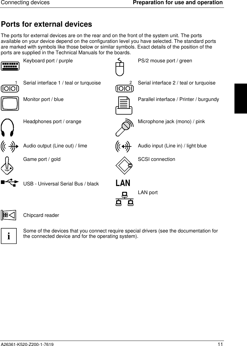
Connecting devices Preparation for use and operationA26361-K520-Z200-1-7619 11Ports for external devicesThe ports for external devices are on the rear and on the front of the system unit. The portsavailable on your device depend on the configuration level you have selected. The standard portsare marked with symbols like those below or similar symbols. Exact details of the position of theports are supplied in the Technical Manuals for the boards.Keyboard port / purple PS/2 mouse port / green1Serial interface 1 / teal or turquoise 2Serial interface 2 / teal or turquoiseMonitor port / blue Parallel interface / Printer / burgundyHeadphones port / orange Microphone jack (mono) / pinkAudio output (Line out) / lime Audio input (Line in) / light blueGame port / gold SCSI connectionUSB - Universal Serial Bus / blackLAN LAN portChipcard readeriSome of the devices that you connect require special drivers (see the documentation forthe connected device and for the operating system).
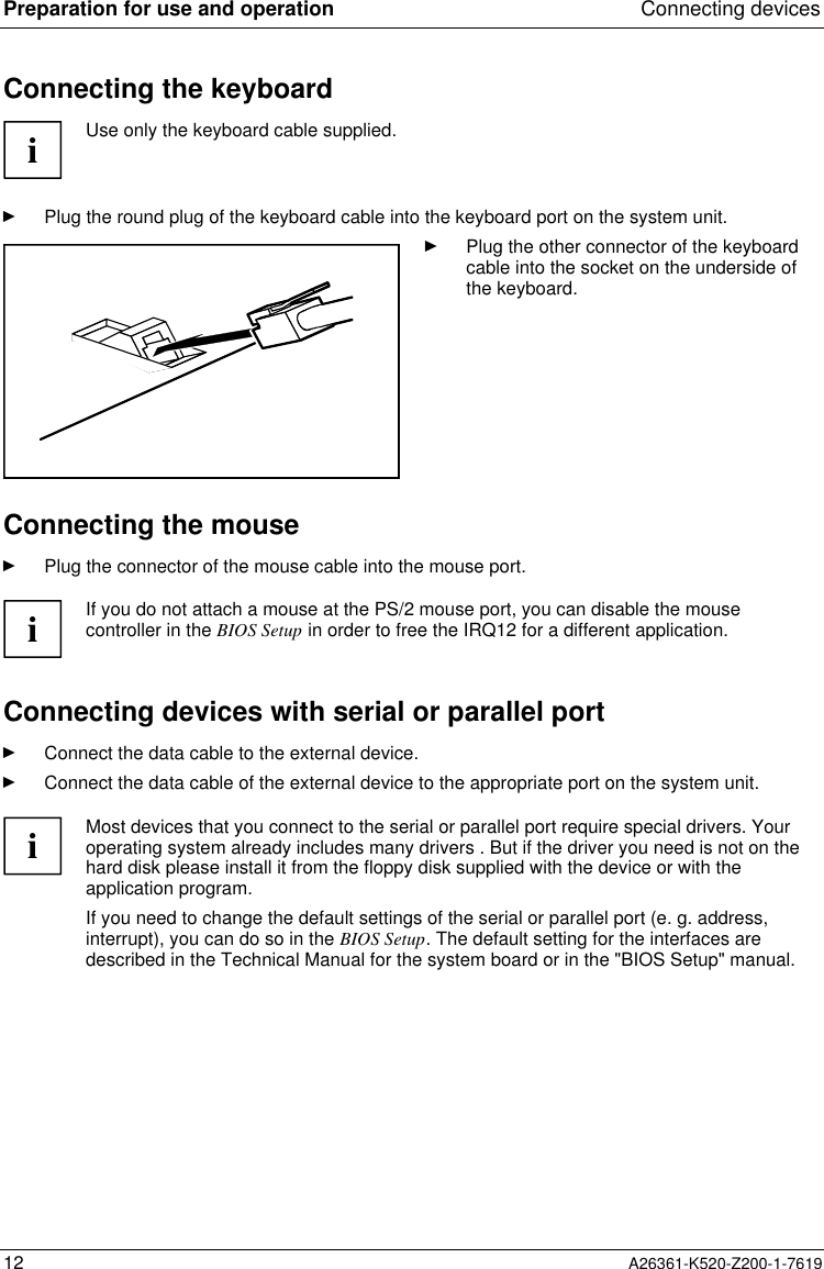
Preparation for use and operation Connecting devices12 A26361-K520-Z200-1-7619Connecting the keyboardiUse only the keyboard cable supplied.Ê  Plug the round plug of the keyboard cable into the keyboard port on the system unit.Ê  Plug the other connector of the keyboardcable into the socket on the underside ofthe keyboard.Connecting the mouseÊ  Plug the connector of the mouse cable into the mouse port.iIf you do not attach a mouse at the PS/2 mouse port, you can disable the mousecontroller in the BIOS Setup in order to free the IRQ12 for a different application.Connecting devices with serial or parallel portÊ  Connect the data cable to the external device.Ê  Connect the data cable of the external device to the appropriate port on the system unit.iMost devices that you connect to the serial or parallel port require special drivers. Youroperating system already includes many drivers . But if the driver you need is not on thehard disk please install it from the floppy disk supplied with the device or with theapplication program.If you need to change the default settings of the serial or parallel port (e. g. address,interrupt), you can do so in the BIOS Setup. The default setting for the interfaces aredescribed in the Technical Manual for the system board or in the "BIOS Setup" manual.
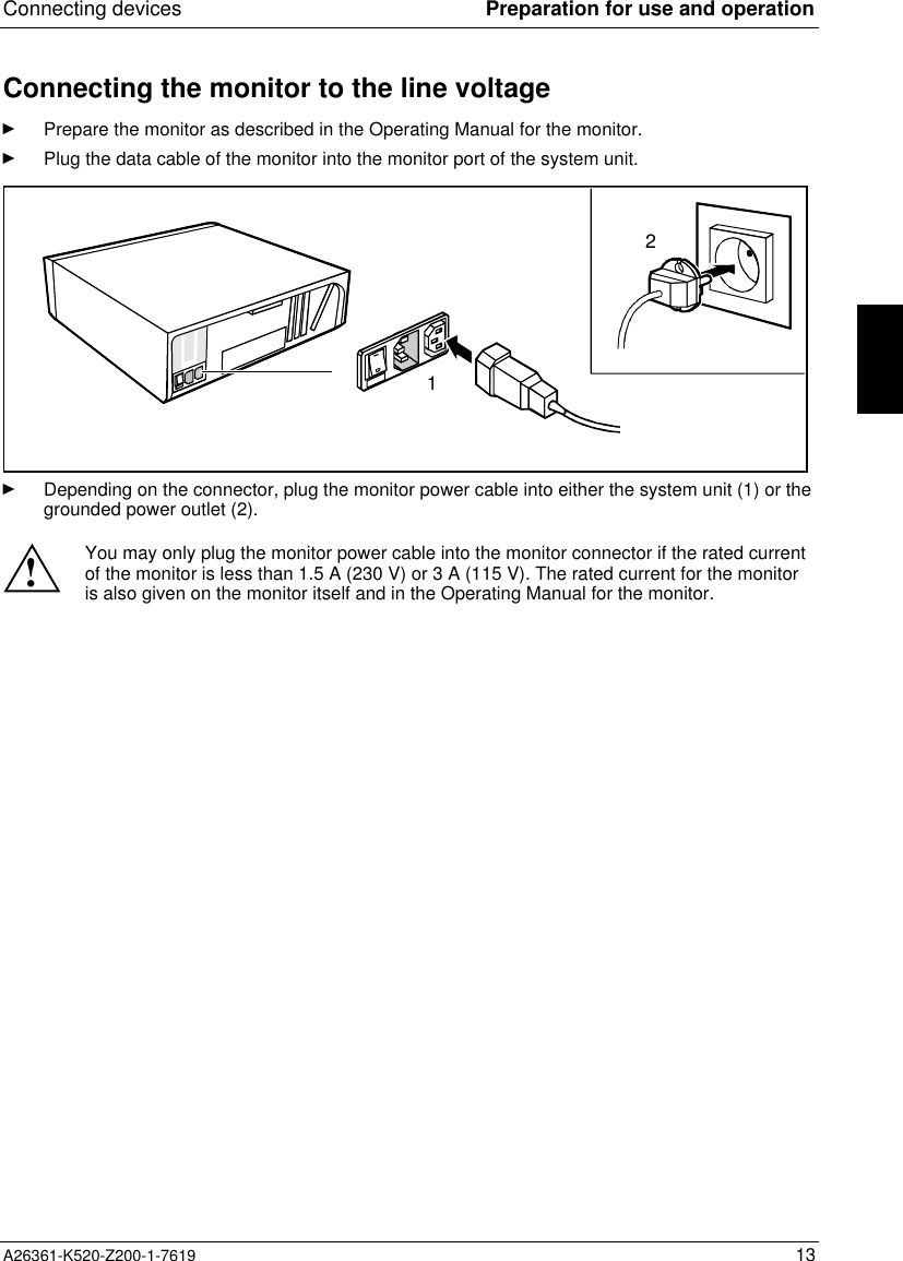
Connecting devices Preparation for use and operationA26361-K520-Z200-1-7619 13Connecting the monitor to the line voltageÊ  Prepare the monitor as described in the Operating Manual for the monitor.Ê  Plug the data cable of the monitor into the monitor port of the system unit.12Ê  Depending on the connector, plug the monitor power cable into either the system unit (1) or thegrounded power outlet (2).!You may only plug the monitor power cable into the monitor connector if the rated currentof the monitor is less than 1.5 A (230 V) or 3 A (115 V). The rated current for the monitoris also given on the monitor itself and in the Operating Manual for the monitor.
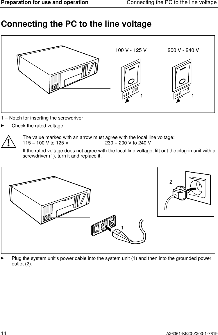
Preparation for use and operation Connecting the PC to the line voltage14 A26361-K520-Z200-1-7619Connecting the PC to the line voltage100 V - 125 V 200 V - 240 V1 11 = Notch for inserting the screwdriverÊ  Check the rated voltage.!The value marked with an arrow must agree with the local line voltage:115 = 100 V to 125 V 230 = 200 V to 240 VIf the rated voltage does not agree with the local line voltage, lift out the plug-in unit with ascrewdriver (1), turn it and replace it.21Ê  Plug the system unit's power cable into the system unit (1) and then into the grounded poweroutlet (2).
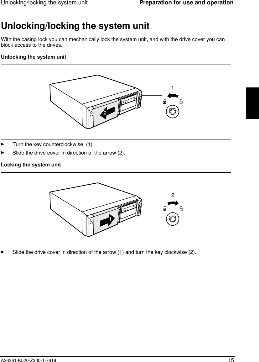
Unlocking/locking the system unit Preparation for use and operationA26361-K520-Z200-1-7619 15Unlocking/locking the system unitWith the casing lock you can mechanically lock the system unit, and with the drive cover you canblock access to the drives.Unlocking the system unit12Ê  Turn the key counterclockwise (1).Ê  Slide the drive cover in direction of the arrow (2).Locking the system unit21Ê  Slide the drive cover in direction of the arrow (1) and turn the key clockwise (2).
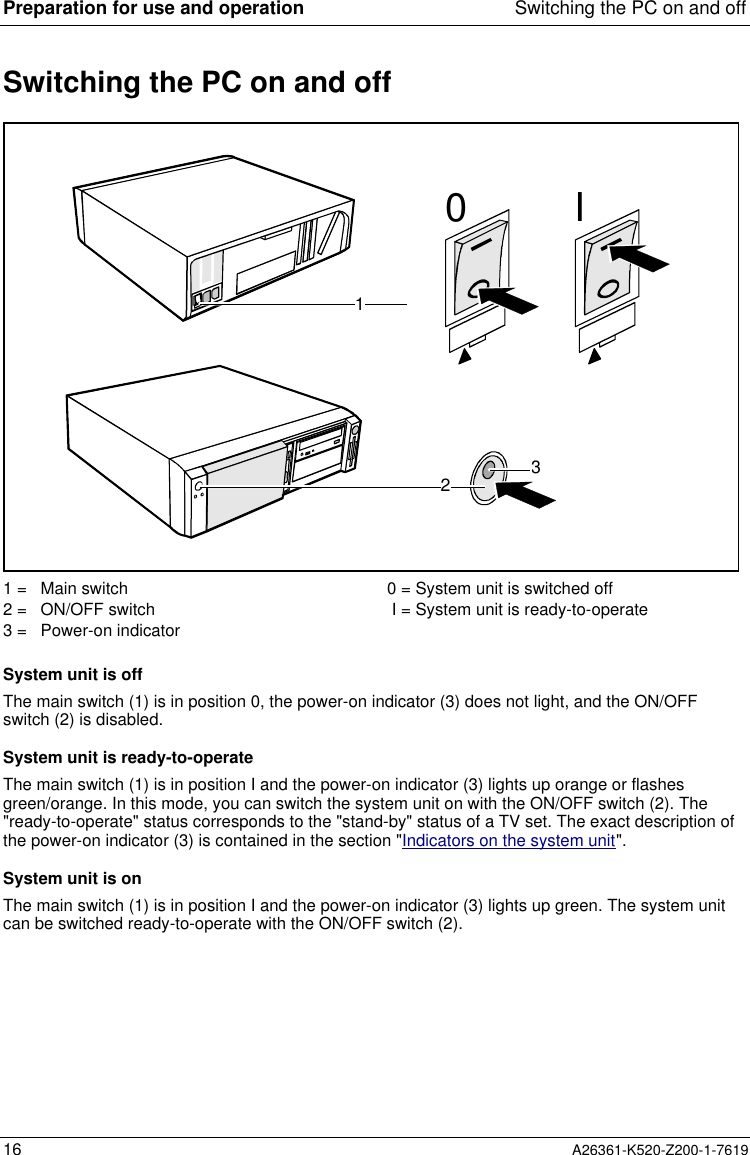
Preparation for use and operation Switching the PC on and off16 A26361-K520-Z200-1-7619Switching the PC on and off1230I1 = Main switch2 = ON/OFF switch3 = Power-on indicator0 = System unit is switched offI = System unit is ready-to-operateSystem unit is offThe main switch (1) is in position 0, the power-on indicator (3) does not light, and the ON/OFFswitch (2) is disabled.System unit is ready-to-operateThe main switch (1) is in position I and the power-on indicator (3) lights up orange or flashesgreen/orange. In this mode, you can switch the system unit on with the ON/OFF switch (2). The"ready-to-operate" status corresponds to the "stand-by" status of a TV set. The exact description ofthe power-on indicator (3) is contained in the section "Indicators on the system unit".System unit is onThe main switch (1) is in position I and the power-on indicator (3) lights up green. The system unitcan be switched ready-to-operate with the ON/OFF switch (2).
Switching the PC on and off Preparation for use and operationA26361-K520-Z200-1-7619 17Switching on the PC for the first timeIf the PC is integrated into a network, the user and server details as well as the network protocol arerequired. Contact your network administrator if you have any questions about these details.When you switch on your PC for the first time the supplied software is set up and configured.If you require the license number of Windows, you will find it either on a sticker on your PC orprinted on the front cover of the Windows manual provided.Ê  Switch your monitor on.Ê  Switch the system unit on with the ON/OFF switch.The power-on indicator lights green and the PC is started.iWhile the PC boots, the screen remains dark for up to a minute depending on the systemconfiguration. To see the start-up messages, you can switch off this standard setting inthe BIOS Setup in the Quiet Boot entry.Ê  Adjust the brightness if necessary (see the Operating Manual for the monitor).iSome variants require you to start the software installation by pressing the function key[F1][F1][F1][F1].Once the installation has been started the PC must not be switched off.You should only reboot the PC during installation if you are requested to do so. Otherwisethe installation will be not be performed correctly. If a fault occurs in the installation thecontents of the hard disk must be completely restored.Ê  During installation follow the instructions on the screen.Consult the operating system manual if there is anything unclear about the requested input data.Some system configurations do not include a Windows CD in the delivery package. In this case youshould create a backup copy after installing Windows so that you can restore the hard disk contentsin an emergency.You need about 40 diskettes for this.Ê  Create Windows diskettes with the MSCSD backup program (create system diskettes) and labelthem using the labels supplied.iYou will find further information about the system, drivers, utilities, updates, and manualsetc. on the "Drivers & Utilities" CD supplied.
Preparation for use and operation Switching the PC on and off18 A26361-K520-Z200-1-7619Switching on the PCÊ  Switch the monitor on (see the Operating Manual for the monitor).Ê  Switch the system unit on with the main switch at the rear of the system unit.Ê  If the power-on indicator lights orange, press the ON/OFF switch at the front of the system unit.The power-on indicator lights green and the PC is started.!While the PC boots, the screen remains dark for up to a minute depending on the systemconfiguration. To see the start-up messages, you can switch off this standard setting inthe BIOS Setup in the Quiet Boot entry.If you have assigned the system password, you must enter this when requested to do so,in order to start the operating system.Switching off the PCÊ  Shut down the operating system Windows properly in the Start menu via the Quit function.Ê  If the operating system does not automatically switch the system unit off, switch the systemunit to ready-to-operate by pressing the ON/OFF switch or turn it off by pressing the mainswitch when requested to do so.If the system unit is ready-to-operate, the power-on indicator lights up orange. The system unitconsumes a minimum of energy and can be switched on by an external device (provided that theremote-on functionality is set to Enabled in the BIOS Setup).When the system unit is switched off with the main switch the power-on indicator is dark afterapprox. 15 seconds. The system unit no longer uses any power.iThe main switch and the ON/OFF switch do not disconnect the system unit from the linevoltage. To disconnect the line voltage completely, remove the power plug from thesocket.Ê  Switch the monitor off (see the Operating Manual for the monitor).Placing a PC (with soft power off function) in a ready-to-operate state by means of softwarePrerequisite: Your system must support switching off with software and this functionality must beenabled in BIOS Setup (Soft Power OFF - Enabled). In addition, the soft off software must be installedon Windows NT systems.You can switch your PC ready-to-operate under Windows 9x and Windows NT via the Shutdown theComputer menu or by using the DeskOff program.
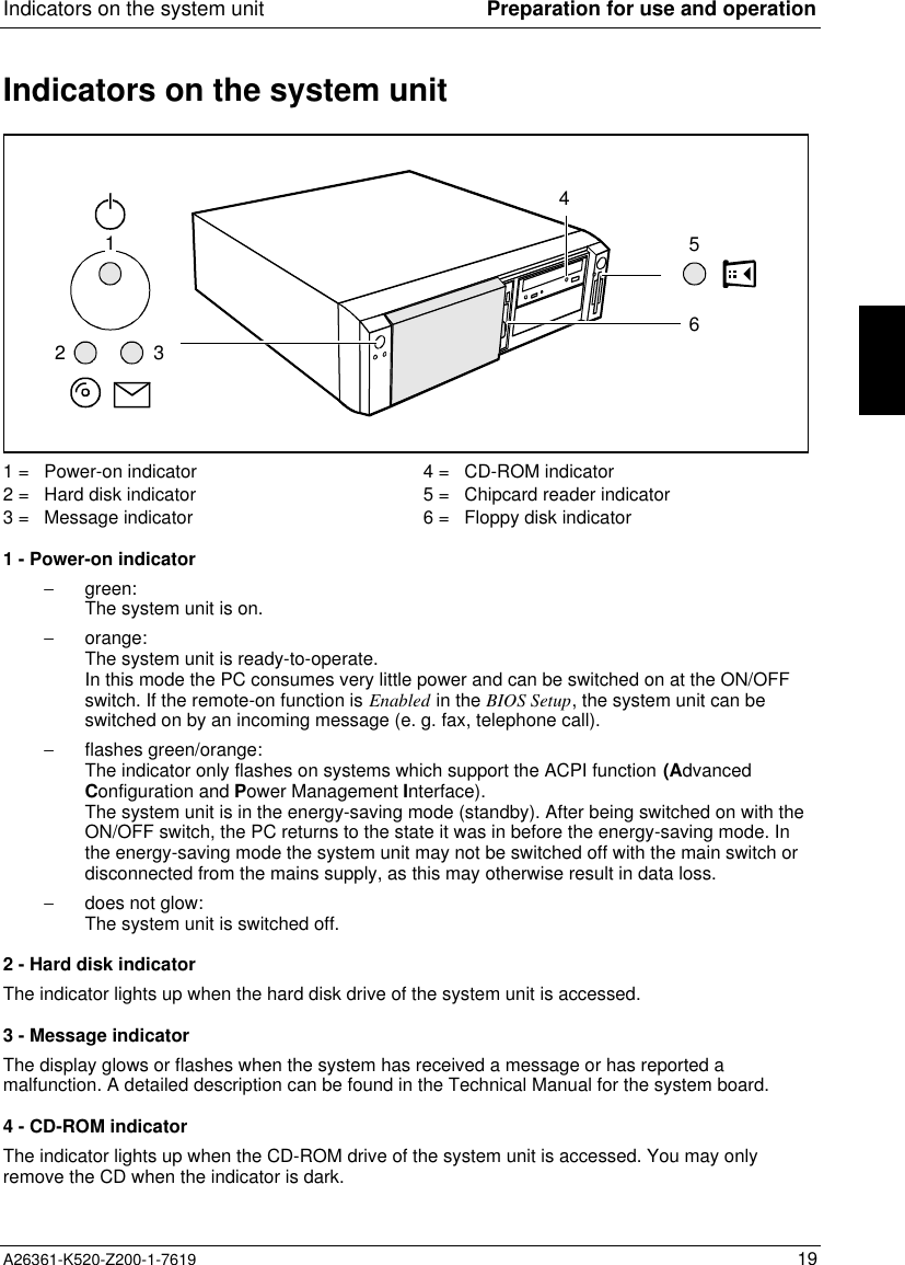
Indicators on the system unit Preparation for use and operationA26361-K520-Z200-1-7619 19Indicators on the system unit2314561 = Power-on indicator2 = Hard disk indicator3 = Message indicator4 = CD-ROM indicator5 = Chipcard reader indicator6 = Floppy disk indicator1 - Power-on indicator−  green:The system unit is on.−  orange:The system unit is ready-to-operate.In this mode the PC consumes very little power and can be switched on at the ON/OFFswitch. If the remote-on function is Enabled in the BIOS Setup, the system unit can beswitched on by an incoming message (e. g. fax, telephone call).−  flashes green/orange:The indicator only flashes on systems which support the ACPI function (AdvancedConfiguration and Power Management Interface).The system unit is in the energy-saving mode (standby). After being switched on with theON/OFF switch, the PC returns to the state it was in before the energy-saving mode. Inthe energy-saving mode the system unit may not be switched off with the main switch ordisconnected from the mains supply, as this may otherwise result in data loss.−  does not glow:The system unit is switched off.2 - Hard disk indicatorThe indicator lights up when the hard disk drive of the system unit is accessed.3 - Message indicatorThe display glows or flashes when the system has received a message or has reported amalfunction. A detailed description can be found in the Technical Manual for the system board.4 - CD-ROM indicatorThe indicator lights up when the CD-ROM drive of the system unit is accessed. You may onlyremove the CD when the indicator is dark.
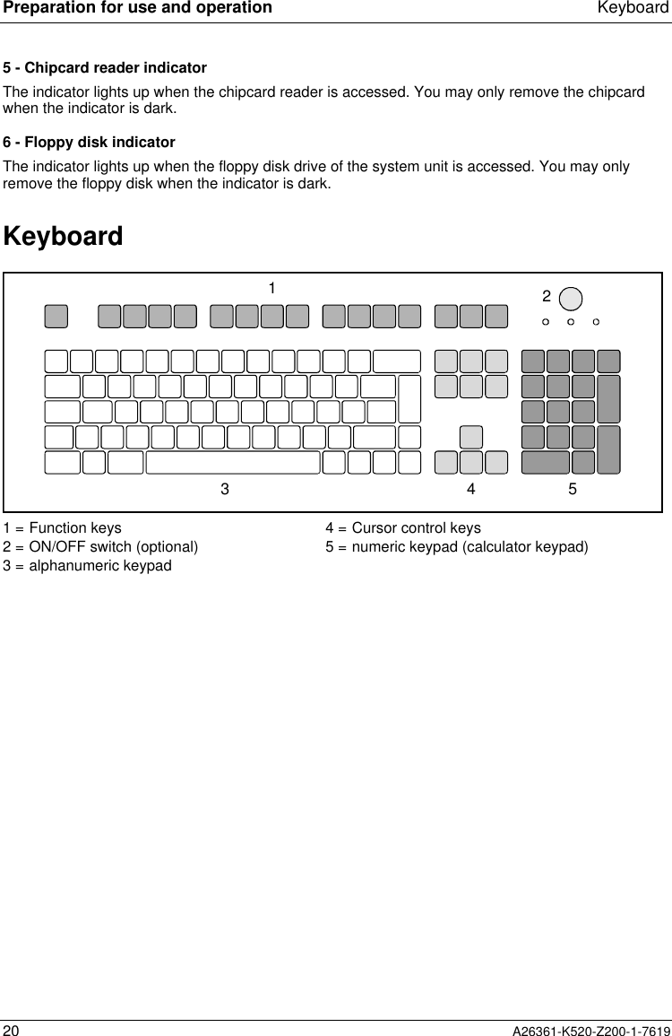
Preparation for use and operation Keyboard20 A26361-K520-Z200-1-76195 - Chipcard reader indicatorThe indicator lights up when the chipcard reader is accessed. You may only remove the chipcardwhen the indicator is dark.6 - Floppy disk indicatorThe indicator lights up when the floppy disk drive of the system unit is accessed. You may onlyremove the floppy disk when the indicator is dark.Keyboard134521 = Function keys2 = ON/OFF switch (optional)3 = alphanumeric keypad4 = Cursor control keys5 = numeric keypad (calculator keypad)
Keyboard Preparation for use and operationA26361-K520-Z200-1-7619 21Important keys and key combinationsThe following description of keys and key combinations refers to MS Windows. Details of other keysand key combinations can be found in the documentation of the relevant application program.ON/OFF switchDepending on the setting in the BIOS setup, the system can be switched on, off or onand off with this switch.Enter keyconfirms or starts the marked selection. The enter key is also referred to as the"Return" key or "Carriage Return".Start keyinvokes the START menu of Windows.Menu keyinvokes the menu for the marked item.Shift keyenables upper-case letters and the upper key symbols to be displayed.Alt Gr Alt Gr (e.g. German keyboard)produces a character shown on the right-hand side of a key (e. g. the character "\"on the key [ß][ß][ß][ß]).%5$4Euro keyenables the output of the euro symbol.Num Num Lock keyby pressing the Num Lock key you switch between the upper- and lower-case levelsof the calculator keypad.At upper-case level (Num Lock indicator lit) the digit and comma keys are active.At lower-case level (Num Lock indicator not lit) the cursor control functions areactive in the calculator keypad.Ctrl Ctrl keystarts key combination actions.Ctrl Alt DelWarm bootrestarts your PC. First hold down the [Ctrl][Ctrl][Ctrl][Ctrl] and [Alt][Alt][Alt][Alt] key, andthen press the [Del][Del][Del][Del] key. With Windows 9x the Task Managerappears first. The warm start is then carried out the secondtime.
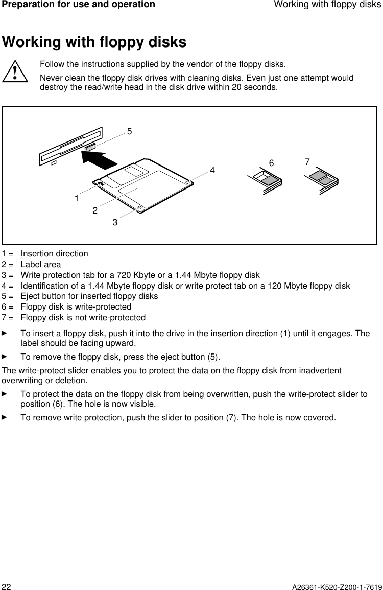
Preparation for use and operation Working with floppy disks22 A26361-K520-Z200-1-7619Working with floppy disks!Follow the instructions supplied by the vendor of the floppy disks.Never clean the floppy disk drives with cleaning disks. Even just one attempt woulddestroy the read/write head in the disk drive within 20 seconds.32156471 = Insertion direction2 = Label area3 = Write protection tab for a 720 Kbyte or a 1.44 Mbyte floppy disk4 = Identification of a 1.44 Mbyte floppy disk or write protect tab on a 120 Mbyte floppy disk5 = Eject button for inserted floppy disks6 = Floppy disk is write-protected7 = Floppy disk is not write-protectedÊ  To insert a floppy disk, push it into the drive in the insertion direction (1) until it engages. Thelabel should be facing upward.Ê  To remove the floppy disk, press the eject button (5).The write-protect slider enables you to protect the data on the floppy disk from inadvertentoverwriting or deletion.Ê  To protect the data on the floppy disk from being overwritten, push the write-protect slider toposition (6). The hole is now visible.Ê  To remove write protection, push the slider to position (7). The hole is now covered.

Navigation menu