Fluke Electronics VERSIV2 CableAnalyzer User Manual Verisiv Part 1
Fluke Electronics CableAnalyzer Verisiv Part 1
Contents
- 1. User Manual DSX 302
- 2. User Manual Statement
- 3. User Manual Verisiv Part 1
- 4. User Manual Verisiv Part 2
- 5. User Manual Verisiv Part 3
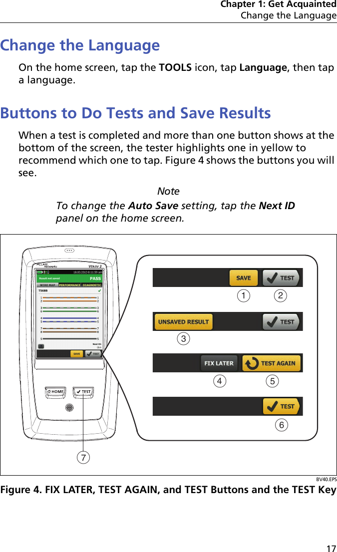
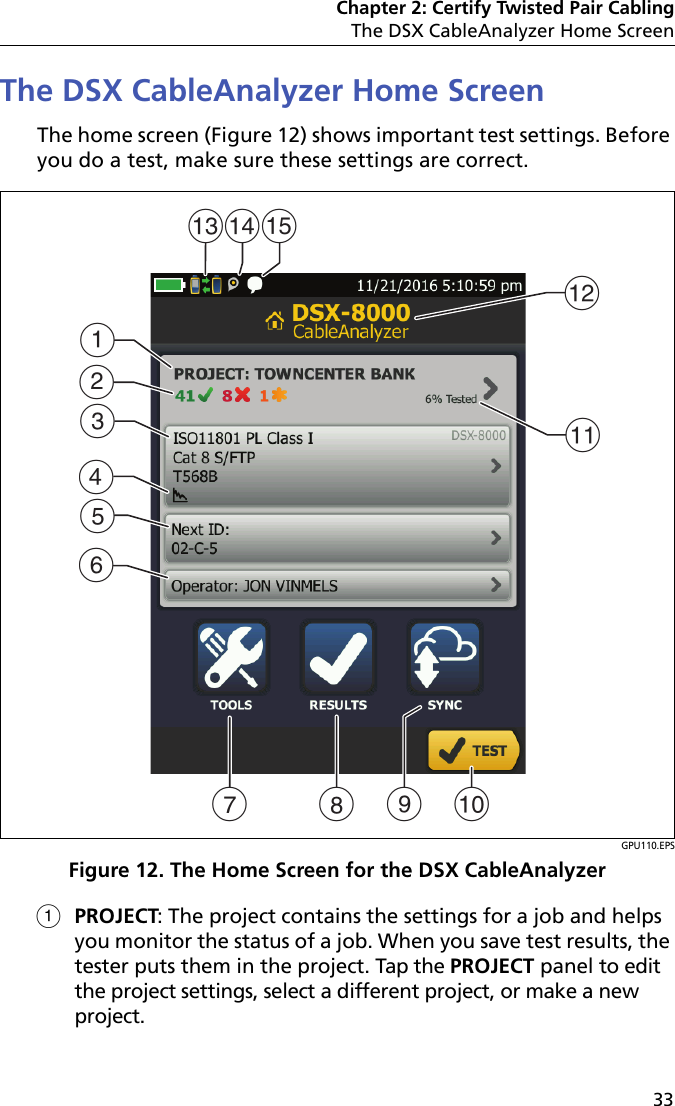
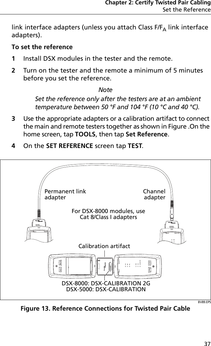
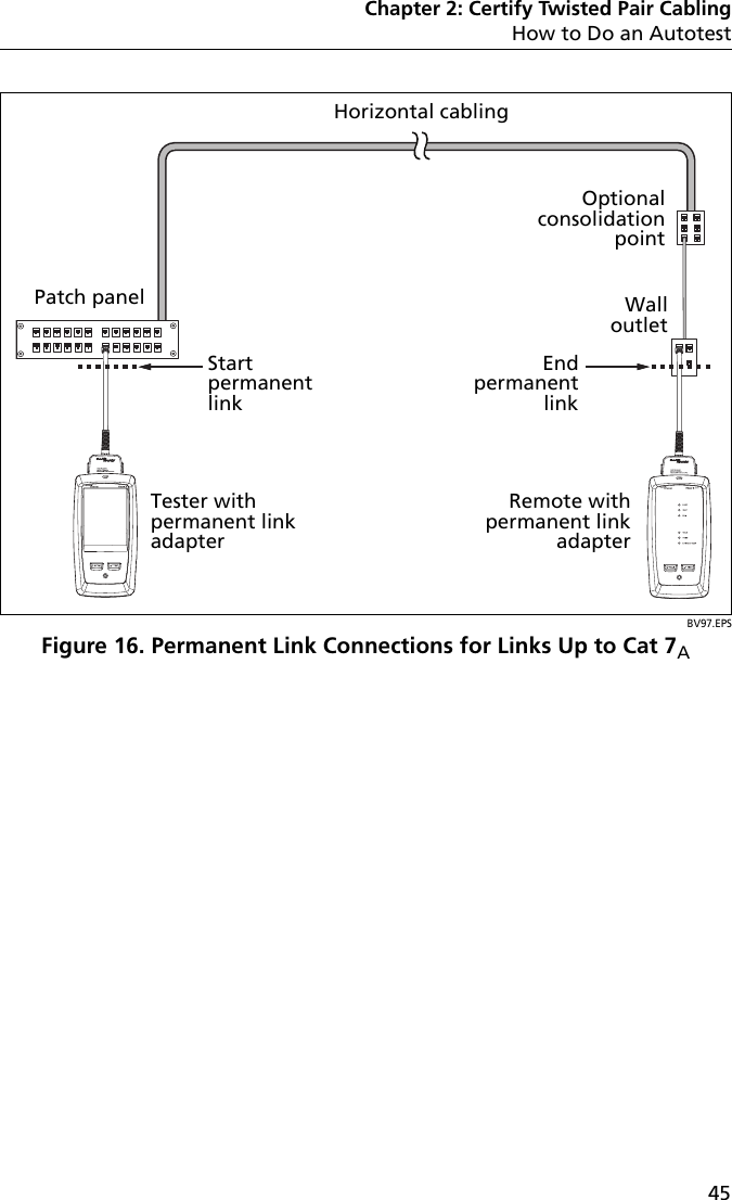
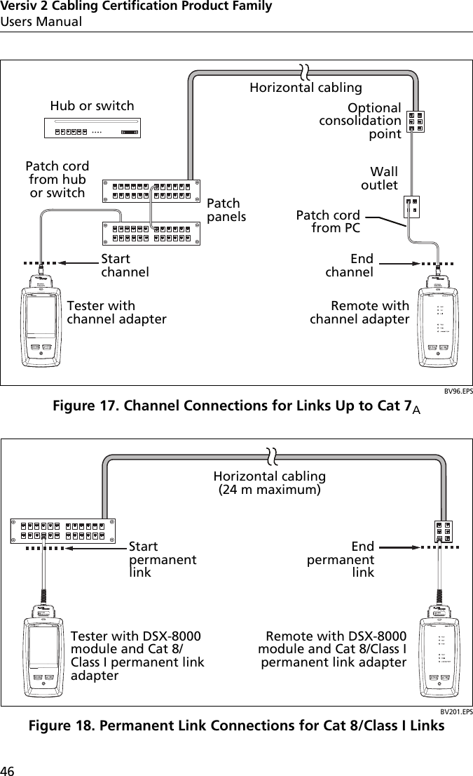
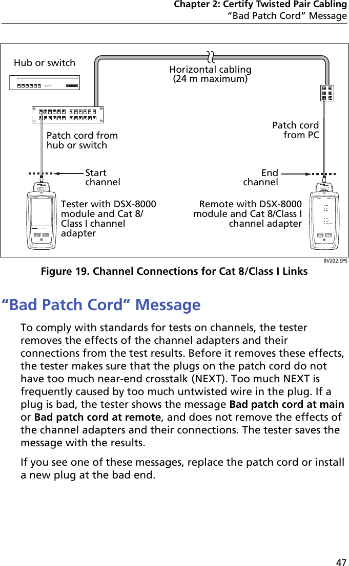
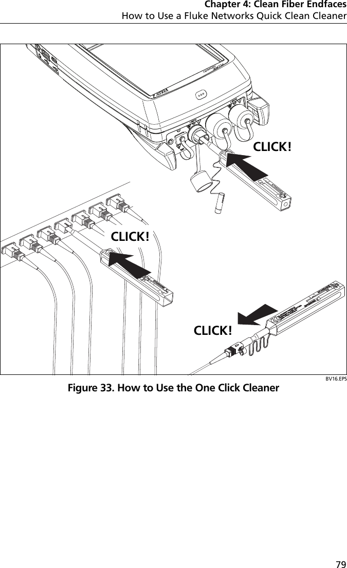
User Manual Verisiv Part 1