Firetide 5900-1 5900 Mesh Node User Manual Part 2
Firetide Inc. 5900 Mesh Node Part 2
UserManual.wiki
>
Firetide
>
5900-1 User Manual
>
User Manual Part 2
Contents
1.
5900_HotViewPro_Manual_3 Part 1
2.
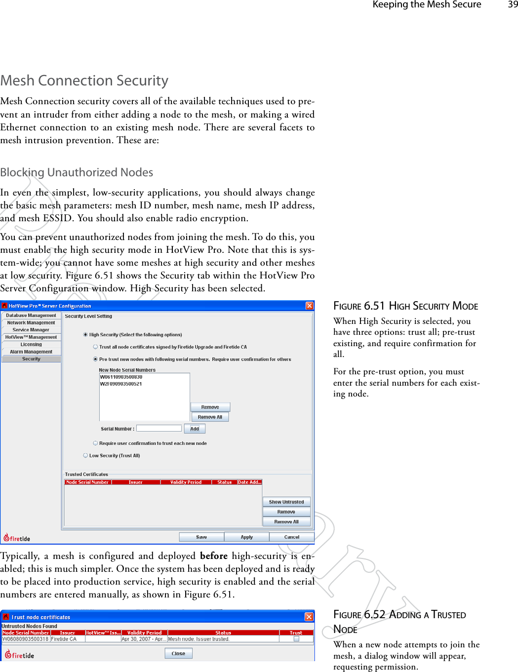
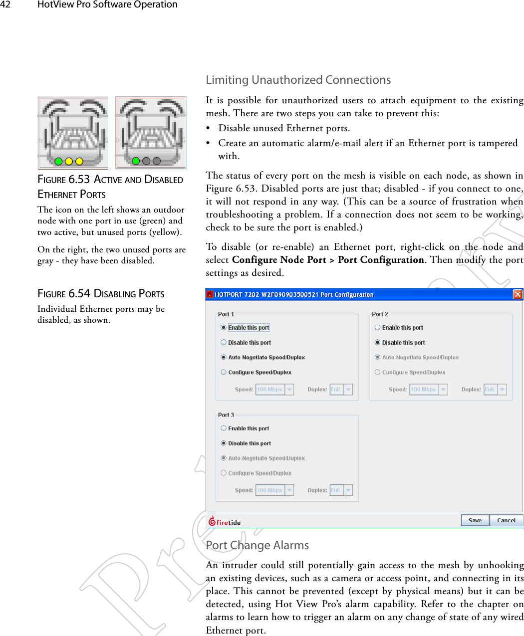
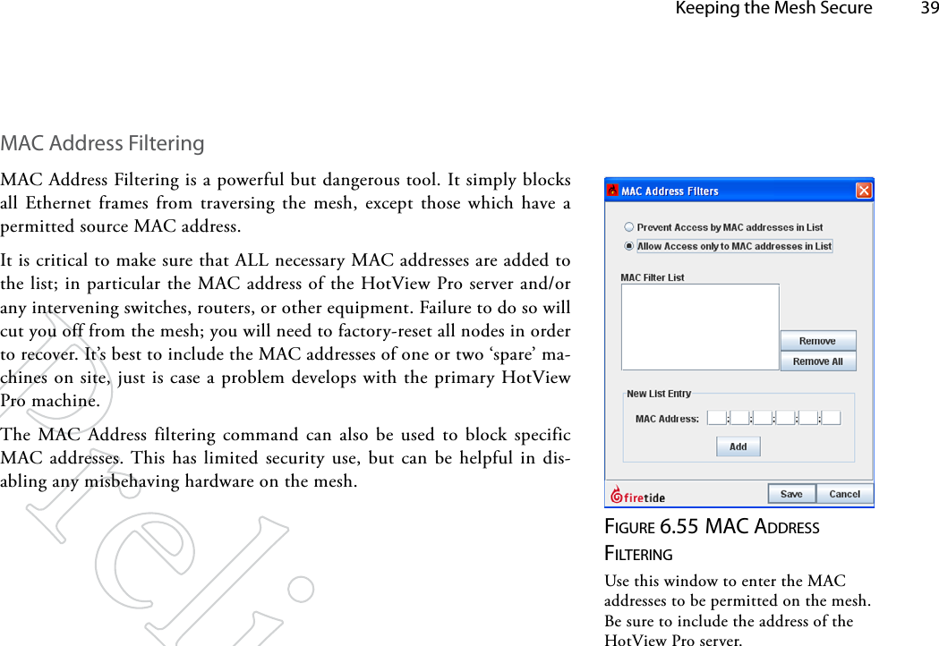
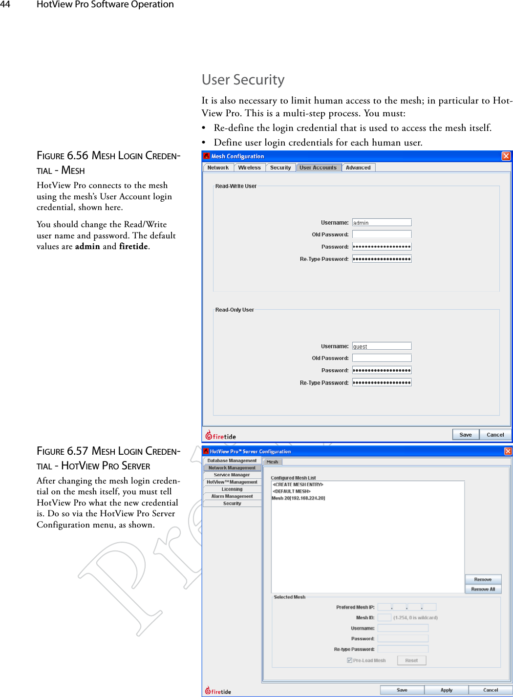
5900_HotViewPro_Manual_3 Part 2
3.
Quick Installation Guide
4.
User Manual Part 1
5.
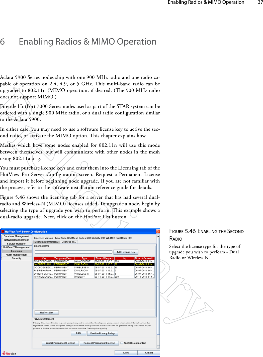
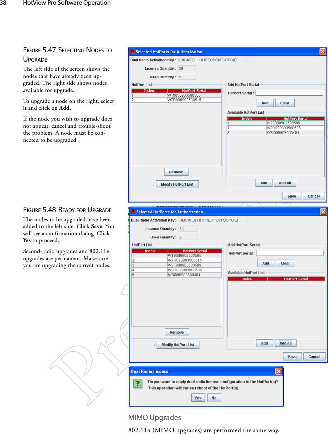
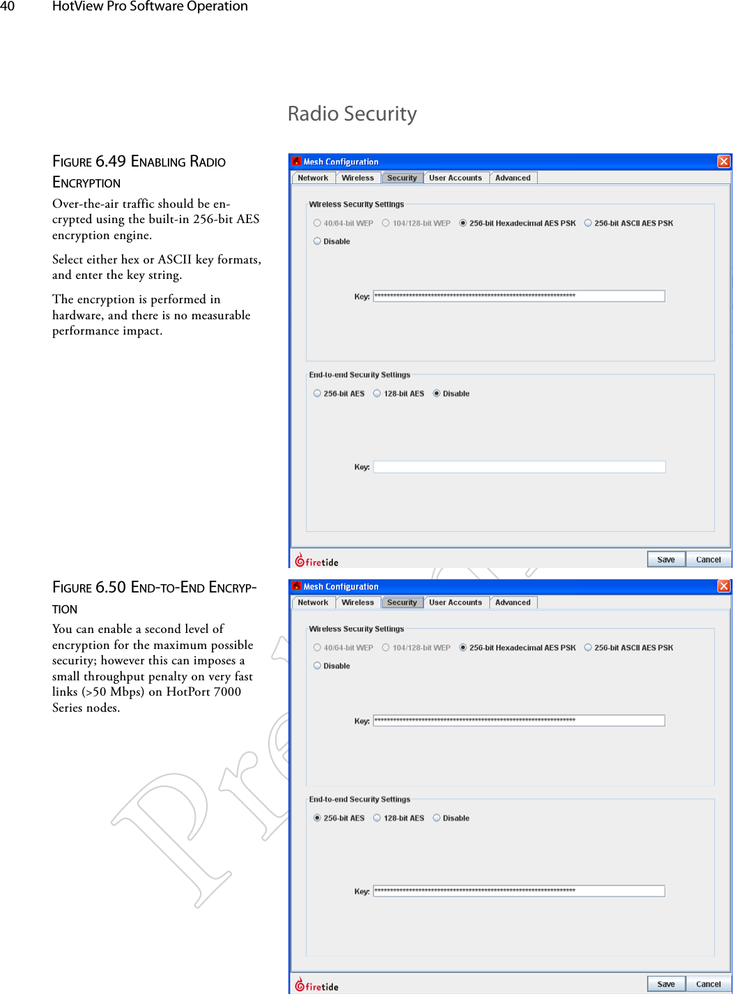
User Manual Part 2
User Manual Part 2
Navigation menu
Upload a User Manual
Namespaces
Wiki Guide
HTML
PDF
Info
Views
User Manual
Discussion / Help
Navigation