FLYSKY RC MODEL TECHNOLOGY FG400 Noble(NB4) User Manual
FLYSKY RC MODEL TECHNOLOGY CO., LTD Noble(NB4)
UserManual.wiki
>
FLYSKY RC MODEL TECHNOLOGY
>
FG400 User Manual
User manual
Navigation menu
Upload a User Manual
Namespaces
Wiki Guide
HTML
PDF
Info
Views
User Manual
Discussion / Help
Navigation

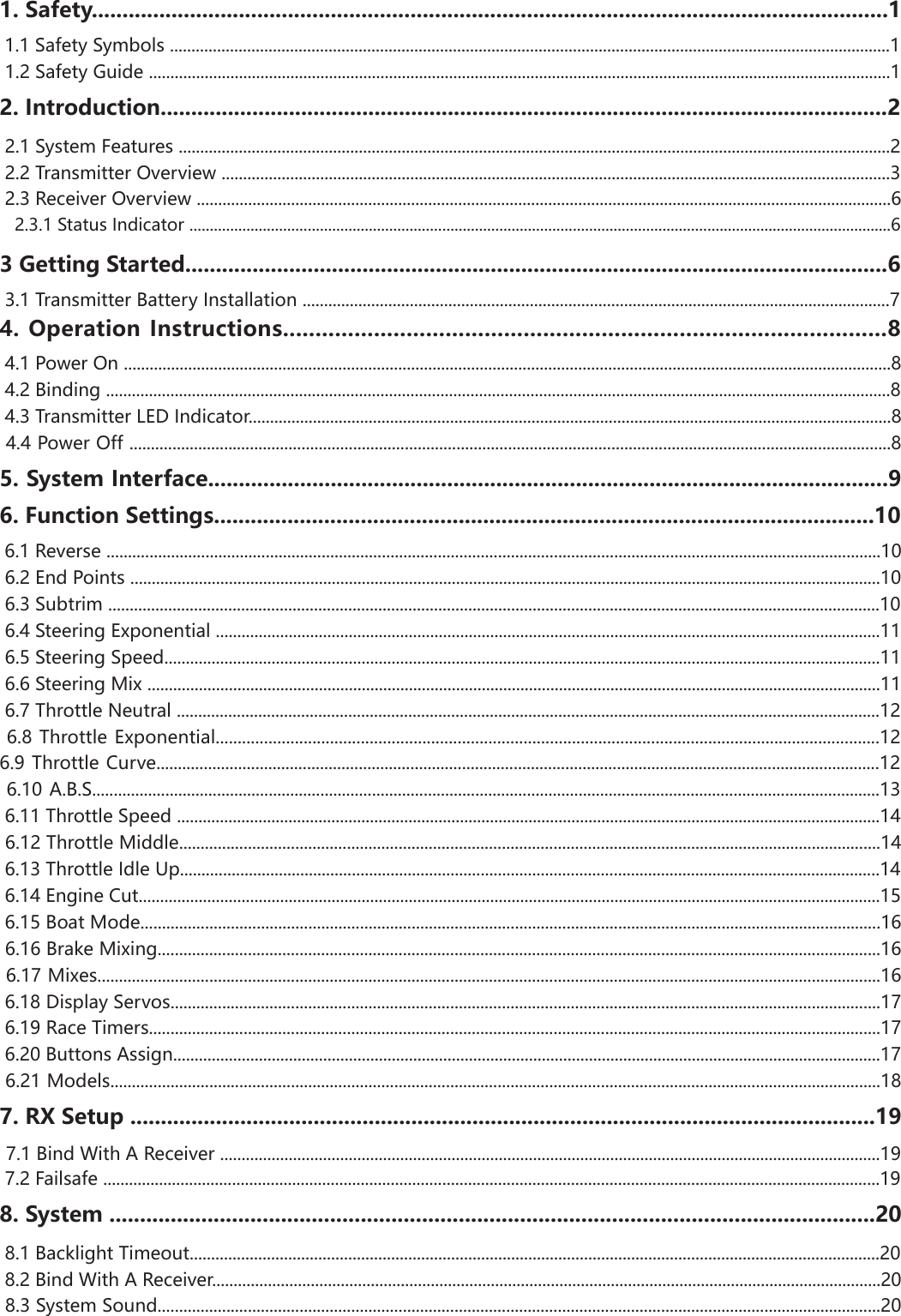
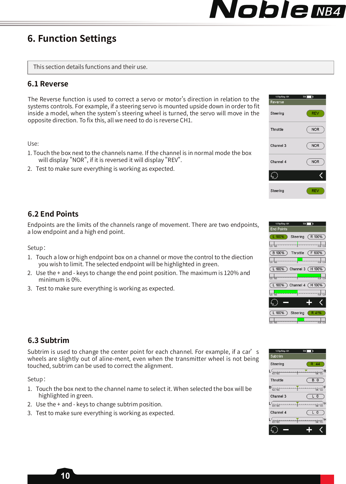
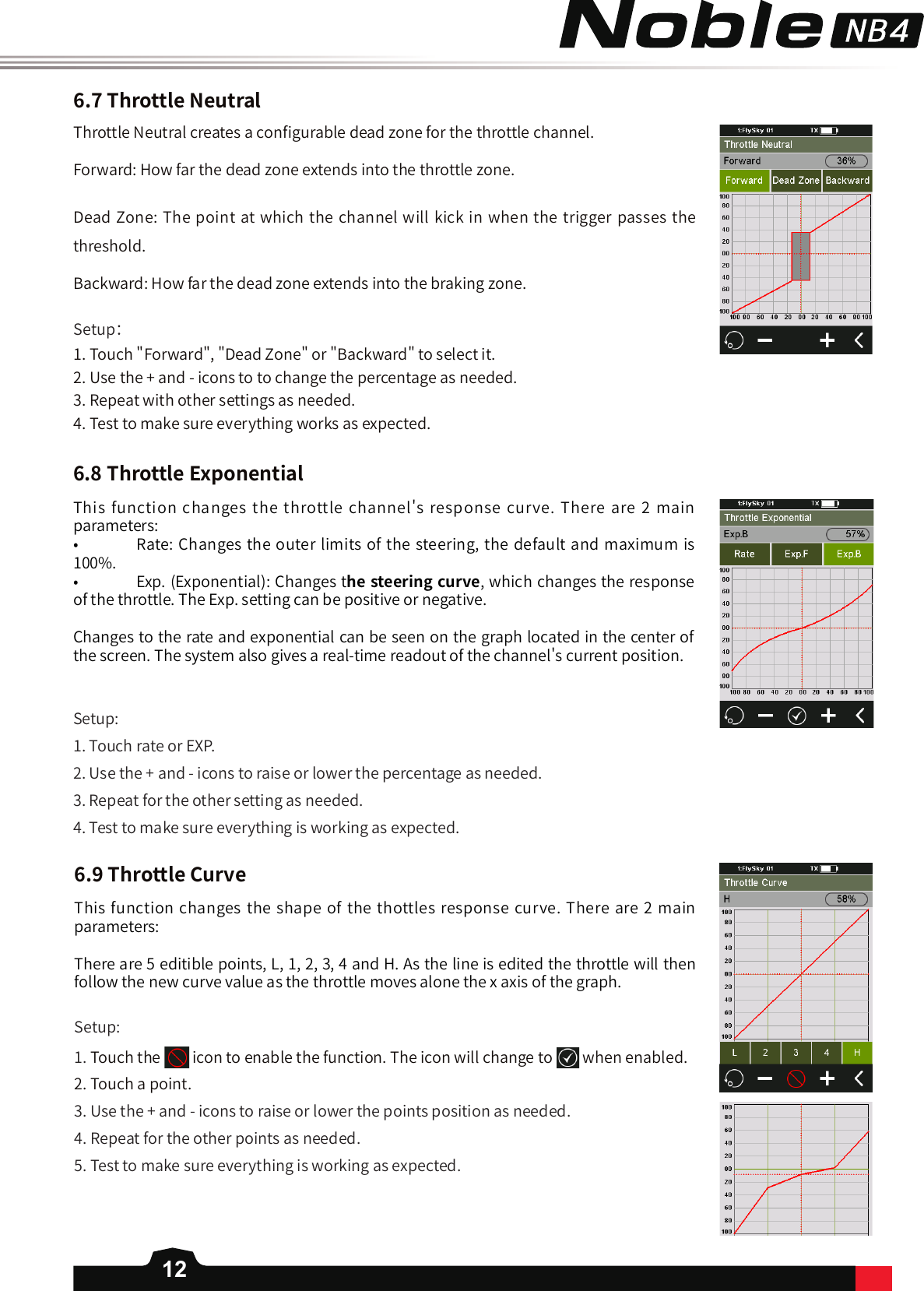
![11This function changes the steering channel's response curve. There are 2 main parameters:• Rate: Changes the outer limits of the steering, the default and maximum is 100%. • Exp. (Exponential): Changes the steering curve, which changes the response of the steering wheel. The Exp. setting can be positive or negative. Changes to the rate and exponential can be seen on the graph located in the center of the screen. The system also gives a real-time readout of the channel's current position.Setup:1. Touch rate or EXP.2. Use the + and - icons to raise or lower the percentage as needed. 3. Repeat for the other setting as needed. 4. Test to make sure everything is working as expected. 6.4SteeringExponential6.5SteeringSpeed6.6SteeringMixSteering Speed changes the speed that the steering channel moves. This function is also used to simulate a realistic wheel turn speed for scale models. Turn Speed: Slows down the steering movement when moving away from the center point.Return Speed: Slows down steering movement when moving towards the center point.Setup:1. Touch "Turn Speed" or "Return Speed" to select it. When selected the box will turn green. 2. Use the + and - icons to change the turning speed percentage.3. Repeat with other setting as needed. 4. Test to make sure everything works as expected. This function changes which wheels are involved in steering, front, rear, or 4-wheel steering. It is set to [Standard] by default, which means front wheel steering. To change steering mode select "Crawler" then select the desired steering type. Note: In crawler mode, CH3 cannot be controlled independently.](https://usermanual.wiki/FLYSKY-RC-MODEL-TECHNOLOGY/FG400/User-Guide-4015835-Page-15.png)
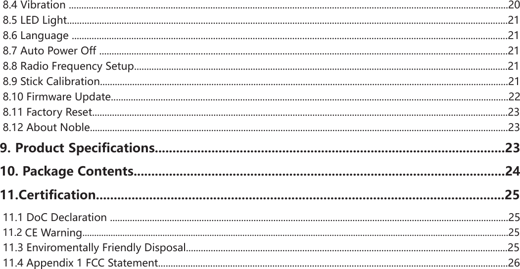
![136.10A.B.S.A.B.S. stands for auto breaking system. This function is used to stop the wheels from locking which can lead to loss of control or a skid. A.B.S. manages this by regulating the amount of pressure the breaks use, which is done by pumping the breaks on and off rather than a constant force. There are six sub menus for A.B.S. function setting, [Brake return], [Delay], [Cycle length], [Trigger point], [Duty cycle], and [Steering mix].In the submenus, pulses are shown as a square wave, the peaks indicating brake on, and troughs in-dicating reduction in braking. As the value changes, the square wave will change to represent the function's current settings. The trigger point is represented as a white line on the graph.Below the graph is a bar that shows the real-time braking position. When this function is active and the brake is applied, the green bar will oscillate in real time showing the A.B.S. in action.BreakReturnControls the reduction of braking during each pulse. If set to 60%, when the brakes are active; the system will remove 60% of the brakes strength on each pulse.DelayDetermines how long it takes for the A.B.S. system to take eect. At a setting of 0%, the A.B.S. system will take eect as soon as the brake is applied. The higher the value, the longer it will take for the A.B.S. to function.CycleLengthIncreases or decreases the time between pulses. The higher the value, the longer the pulse. TriggerPointConfigures the point at which the A.B.S. starts to function. The higher the percentage, the further the trigger has to be moved to activate the A.B.S.To activate this function press the icon. The icon will change to when active.](https://usermanual.wiki/FLYSKY-RC-MODEL-TECHNOLOGY/FG400/User-Guide-4015835-Page-17.png)
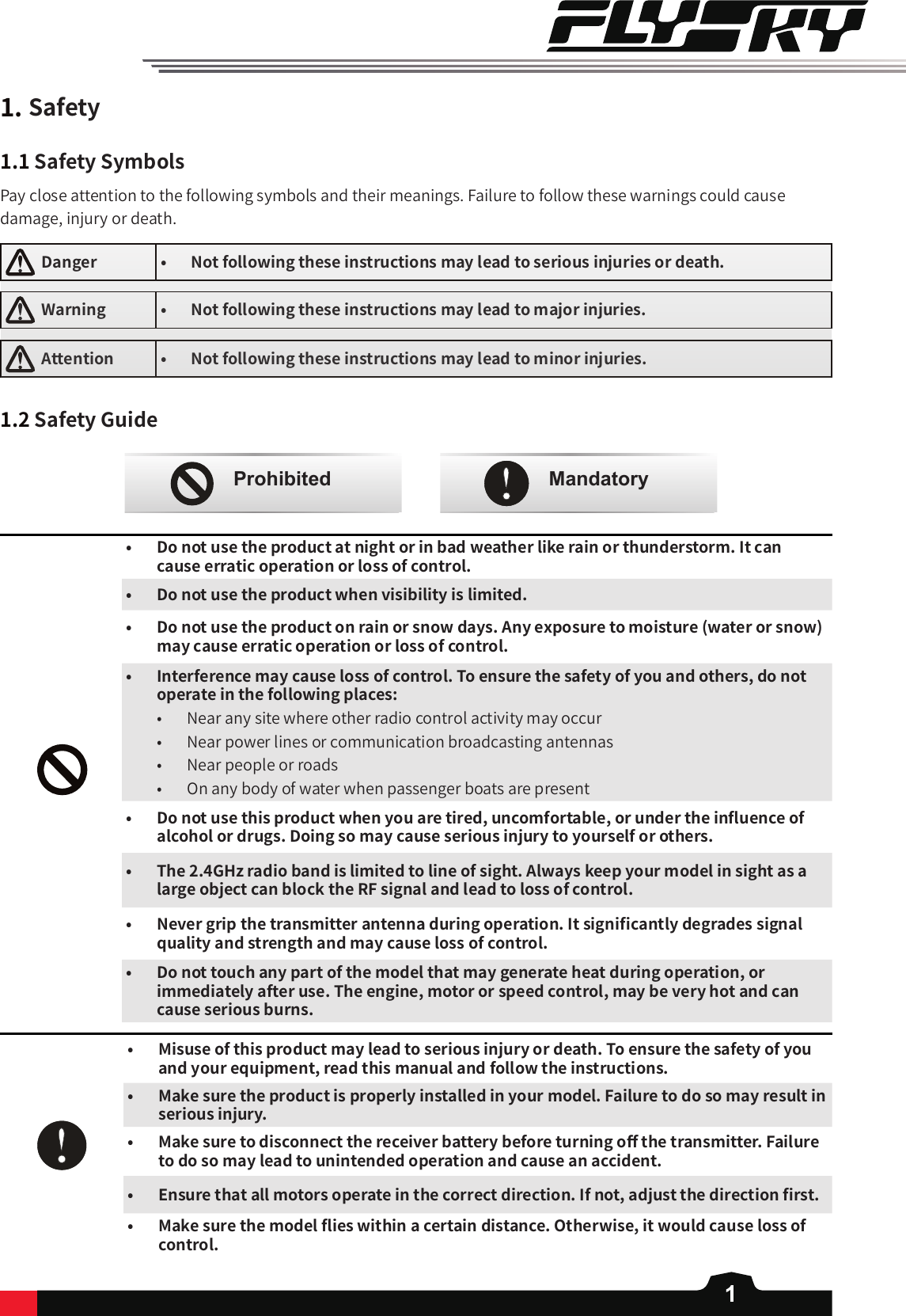
![14DutyCycleChanges the length of each pulse and the gap between them. As the value changes, the length of the braking waves peaks and troughs will change independently of each other and will no longer be symmetrical.SteeringMixA.B.S. can be reduced automatically while turning. This function mixes braking and steering to turn reduce the A.B.S. or replace it with a constant braking pressure.v6.11ThrottleSpeedThrottle Speed changes how quickly the throttle will react, for both braking and throttle.There are 2 settings for brake and throttle:• Go: Sets how quickly the throttle applies acceleration. • Return: Sets how quickly the throttle backs o. The lower the percentage the longer it will take for the throttle to catch up with the trigger movement. The bar in the middle of the screen will show the throttle's current position in real time. The red bar is the triggers current position; the green bar is the channels current posi-tion. Setup:1. Select the desired setting, [Go] or [Return].2. Use the + or - icons to change the percentage. 3. Repeat with the other settings as needed. 4. Test to make sure everything works as expected. 6.12ThrottleMiddleThis function changes the midpoint of the throttle, and could be used to correct the servo position. If the servo position is wrong, the model may move as soon as it's turned on.Setup: 1. Use the + and - keys to change the throttle middle position. 2. Test to make sure everything is working as expected.](https://usermanual.wiki/FLYSKY-RC-MODEL-TECHNOLOGY/FG400/User-Guide-4015835-Page-18.png)
![156.13ThrottleIdleUpThrottle Idle Up is used for models that use a fuel based engine that will stall if left at 0 throttle. Idle up makes sure that the engine always has some throttle in order to keep it from stalling. This function must be assigned to a switch/button in order to be activated (See [Buttons Assign]). If not, the function cannot be activated.Setup: 1. Assign the Throttle Idle Up function to a button. For more information on this see the [Buttons Assign] section of this user manual. Now when the button is press it will toggle Throttle Idle Up on and o. 2. Use the + and - icons to change the percentage. 3. Test to make sure everything works as expected. 6.14EngineCutWhen Engine Cut is triggered via a button it sets the throttle channel to a predefined position. This function must be assigned to a switch/button in order to be activated (See [Buttons Assign]). If not, the function cannot be activated.Setup: 1. Assign the Engine Cut function to a button. For more information on this see the [Buttons Assign] section of this user manual. Now when the button is press it will toggle Engine Cut on and o. 2. Use the + and - icons to change the percentage. 3. Test to make sure everything works as expected.](https://usermanual.wiki/FLYSKY-RC-MODEL-TECHNOLOGY/FG400/User-Guide-4015835-Page-19.png)
![166.15BoatMode6.16BrakeMixingThis function is used only when you are using a model boat. When this function is active, the throttle channel is set to its lowest position and the brake functionality is disabled.To toggle this function, select the box beside [Normal mode]. When the function is active, the text beside the box will change to [Boat mode].This function enables you to use models that require more than one braking channel, for example a model that has separate brakes for front and back braking. If your model uses extra channels for braking, each channel can be controlled separately and are slaves of the throttle channel.Setup: 1. Touch channel 3 or 4 to reveal that channels options. 2. Touch the exponential option to enter the exponential settings.3. Touch rate and use the + and - iconds to change the percentage and do the same for Exp. 4. Touch the icon to return to the brake mixing main menu. 5. Touch A.B.S. to enter the sub menu.6. Refere to the [A.B.S.] section of the user manual for more information on how to set up A.B.S.7. Use the Display Servos function to make sure everything is working as expected. 6.17MixesMixes is used to create a mix between channels. Setup: 1. Touch a mix to select it.2. Touch the icon to enable the function. The icon will change to when enabled.3. Touch "Master Channel", then select a master channel from the list. 4. Touch "Slave Channel", then select a slave channel from the list. 6. Repeat step 5 for the other mix as needed. 7. Touch oset, then use the + and - icons to change the slave channels oset relative to the master. 5. Select [Low side mix] or [High side mix] as needed. Use the + and - icons to change the mix percentage. Press the icon when nished to return to the mix menu.](https://usermanual.wiki/FLYSKY-RC-MODEL-TECHNOLOGY/FG400/User-Guide-4015835-Page-20.png)
![2511.CerticationHereby, [Flysky Technology co., ltd] declares that the Radio Equipment [FG4] is in compliance with RED 2014/53/EU.The full text of the EU DoC is available at the following internet address: www.ysky-cn.com11.1DoCDeclaration11.2CEWarningThe antenna(s) used for this transmitter must be installed to provide a separation distance of at least 20 cm from all persons and must not be co-located or operating in conjunction with any other transmitter. End-users and installers must be provided with antenna installation instructions and transmitter operating conditions for satisfying RF exposure compliance11.3EnvironmentallyfriendlydisposalOld electrical appliances must not be disposed of together with the residual waste, but have to be disposed of separately. The disposal at the communal collecting point via private persons is for free. The owner of old appliances is responsible to bring the appliances to these collecting points or to similar collection points. With this little personal eort, you contribute to recycle valuable raw materials and the treatment of toxic substances.CAUTIONRISK OF EXPLOSION IF BATTERY IS REPLACED BY AN INCORRECT TYPE.DISPOSE OF USED BATTERIES ACCORDING TO THE INSTRUCTIONS](https://usermanual.wiki/FLYSKY-RC-MODEL-TECHNOLOGY/FG400/User-Guide-4015835-Page-29.png)
![26This equipment has been tested and found to comply with the limits for a Class B digital device pursuant to part 15 of the FCC rules. These limits are designed to provide reasonable protection against harmful interference in a residential installation. This equipment generates, uses and can radiate radio frequency energy and, if not installed and used in accordance with the instructions, may cause harmful interference to radio communications. However, there is no guarantee that interference will not occur in a particular installation. If this equipment does cause harmful interference to radio or televison reception, which can be determined by turning the equipment o and on, the user is encouraged to try to correct the interference by one or more of the following measures:Reorient or relocate the receiving antenna.Increase the separation between the equipment and receiver.Connect the equipment into an outlet on a circuit dierent from that to which the receiver is connected.Consult the dealer or an experienced radio/TV technician for help.To assure continued compliance, any changes or modications not expressly approved by the party responsible for compliance could void the user’s authority to operate this equipment. This equipment complies with Part 15 of the FCC Rules. Operation is subject to the following two conditions:(1) This device may not cause harmful interference, and(2) This device must accept any interference received, including interference that may cause undesired operation.Caution!The manufacturer is not responsible for any radio or TV interference caused by unauthorized modications to this equipment. Such modications could void the user authority to operate the equipment.1. Move all your channels to the desired position.2. Select [All channels] and then [Yes] in the conrmation box. 11.4Appendix1FCCStatement](https://usermanual.wiki/FLYSKY-RC-MODEL-TECHNOLOGY/FG400/User-Guide-4015835-Page-30.png)