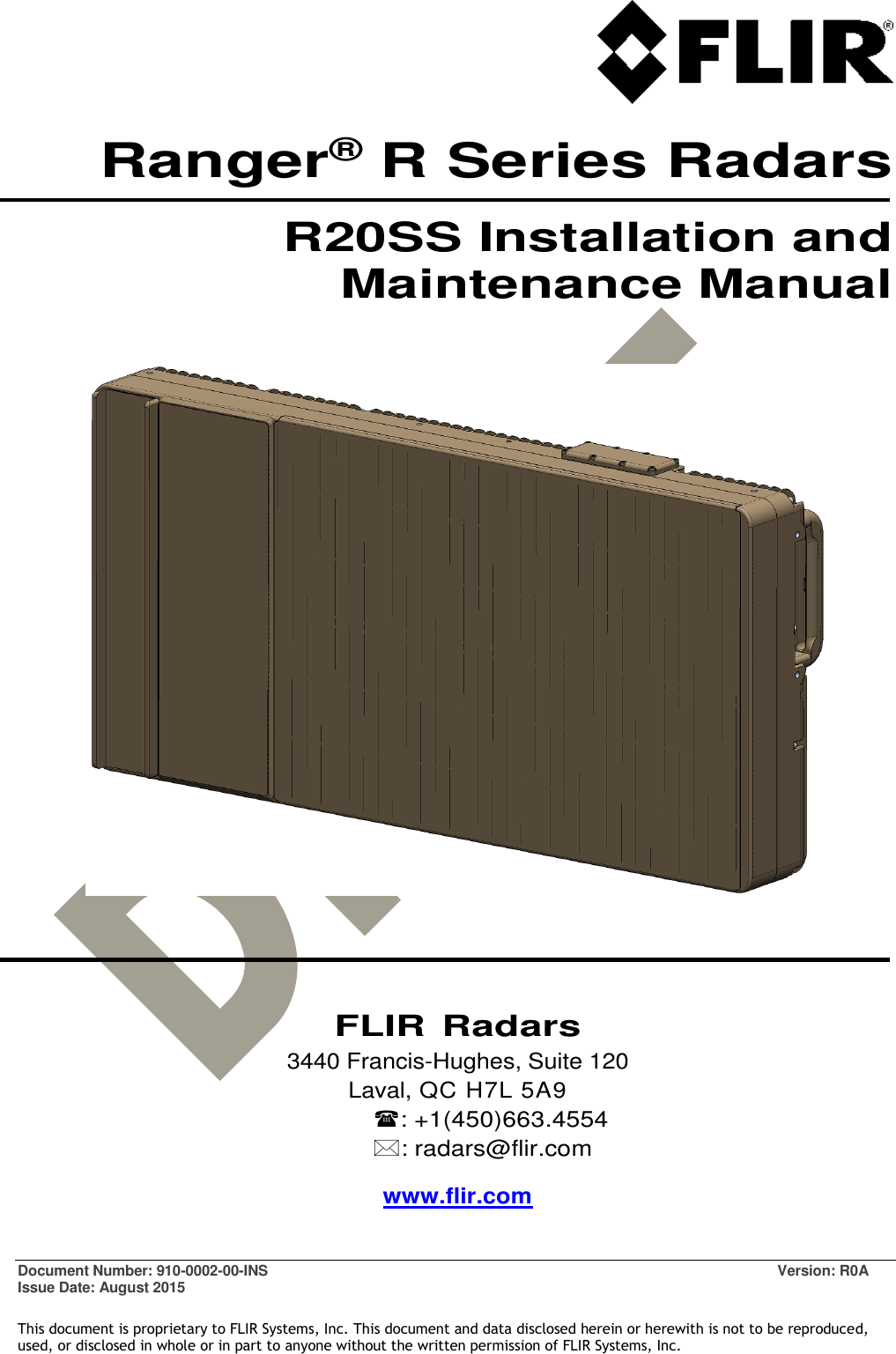
FLIR Radars R20 Ranger Radar User Manual

FLIR Radars Inc. Ranger Radar

User Manual

  Document Number: 910-0002-00-INS  Version: R0A Issue Date: August 2015  This document is proprietary to FLIR Systems, Inc. This document and data disclosed herein or herewith is not to be reproduced, used, or disclosed in whole or in part to anyone without the written permission of FLIR Systems, Inc. Ranger® R Series Radars R20SS Installation and Maintenance Manual         FLIR Radars 3440 Francis-Hughes, Suite 120 Laval, QC H7L 5A9 : +1(450)663.4554 : radars@flir.com www.flir.com
 910-0002-00-INS-R0A  Page 2 of 33  Information contained in this document pertains to a Canadian origin product that is controlled as "dual use" by the Canadian government.  However, when in the United States or possessed by a US person, it may be considered a defense article from the US Government's perspective.  US government authorization may be required for re-transfer to a foreign person.   If you have any questions, please contact FLIR's Global Trade Compliance group at exportquestions@flir.com .  ©2015 FLIR Radars  Reference #910-0002-00-INS-R0A  This documentation is provided as a component of the FLIR radar systems. All parties or individuals who are in possession of the documentation accept in full and without exception or limitation the FLIR Radars unrestricted rights of ownership of this material. This documentation is not available by any other means except by license which is only available from FLIR Radars. Under no circumstances may any part or the whole of this documentation be reproduced, stored in a retrieval system, transmitted, copied, modified, distributed, displayed, sold, licensed, published or derivative works created therefrom in any form or by any means electronic, mechanical, recording, or otherwise without the written permission of FLIR Radars being obtained in advance.  Information contained in this document pertains to a Canadian origin product that is controlled as "dual use" by the Canadian government.  However, when in the United States or possessed by a US person, it may be considered a defense article from the US Government's perspective.  US government authorization may be required for re-transfer to a foreign person. If you have any questions, please contact FLIR's Global Trade Compliance group at exportquestions@flir.com.   It is expressly forbidden for the holder of this documentation to use it either in its entirety or in part or any graphics to provide training or tuition, assistance or knowledge transfer to any other party whatsoever, or for marketing of promotional literature or material of any type whatsoever without the prior written permission of FLIR Radars. Use of this documentation in any manner inconsistent with the user manual and related documentation is strictly prohibited. Use of the documentation is not transferable.
 910-0002-00-INS-R0A  Page 3 of 33  Information contained in this document pertains to a Canadian origin product that is controlled as "dual use" by the Canadian government.  However, when in the United States or possessed by a US person, it may be considered a defense article from the US Government's perspective.  US government authorization may be required for re-transfer to a foreign person.   If you have any questions, please contact FLIR's Global Trade Compliance group at exportquestions@flir.com .   CONTACT INFORMATION  Toll Free North America  1.866.657.4554   +1(450)663.4554   +1(450)663.7134   www.flir.com   radars@flir.com    When sending an e-mail (), please include:  Contact info (e-mail, phone, fax, other as required)  Product model and software version number  If possible, the serial number of the product  A description of the problem/issue  Data recordings and/or log files, if available  Any other pertinent information       DISPOSAL Dispose in accordance with the laws and regulations applicable in your jurisdiction.
 910-0002-00-INS-R0A  Page 4 of 33  Information contained in this document pertains to a Canadian origin product that is controlled as "dual use" by the Canadian government.  However, when in the United States or possessed by a US person, it may be considered a defense article from the US Government's perspective.  US government authorization may be required for re-transfer to a foreign person.   If you have any questions, please contact FLIR's Global Trade Compliance group at exportquestions@flir.com .   REVISION RECORD TABLE     Manual Revision ECO # Pages Description of Modification 1.0 13-008 All PSR Software Version 6.1.0 2.0  All Insertion of ITAR Statement 3.0  All Safety distances added
 910-0002-00-INS-R0A  Page 5 of 33  Information contained in this document pertains to a Canadian origin product that is controlled as "dual use" by the Canadian government.  However, when in the United States or possessed by a US person, it may be considered a defense article from the US Government's perspective.  US government authorization may be required for re-transfer to a foreign person.   If you have any questions, please contact FLIR's Global Trade Compliance group at exportquestions@flir.com .  The following symbols are used throughout this document:  Caution! The CAUTION symbol is used to alert the reader to situations where a hazard to personnel safety may arise.  WARNING!   The WARNING symbol is used to alert the reader to situations where equipment damage is imminent if a recommended process is not followed or alert the reader of a process that will alter or reset current configuration of a specific setup.  DANGER!   The DANGER symbol is used to alert the reader to situations where a hazard to personnel may result in serious injury possibly leading to death.  Disclaimer! Disclaimers provide a means of specifying limitations or other requirements on equipment.  Note Notes comprise additional information to assist the reader in the use or understanding of the equipment or subject.
 910-0002-00-INS-R0A  Page 6 of 33  Information contained in this document pertains to a Canadian origin product that is controlled as "dual use" by the Canadian government.  However, when in the United States or possessed by a US person, it may be considered a defense article from the US Government's perspective.  US government authorization may be required for re-transfer to a foreign person.   If you have any questions, please contact FLIR's Global Trade Compliance group at exportquestions@flir.com .   DEFINITIONS AND ACRONYMS  AXML  Amphitech eXtensible Markup Language BIT  Built-in Test CE  Refers to CE marking, a conformity mark in Europe Doppler  Doppler effect. Also refers to Doppler radar operation mode, where target speed is used to reject fixed clutter. FastScan  Non-Doppler scanning mode featuring a fast update rate FCC  Federal Communications Commission (usually refers to the US agency) FMCW  Frequency Modulated Continuous Wave GPS  Global Positioning System GUI  Graphical User Interface IP  Internet Protocol KBPS  KiloBits Per Second LAN  Local Area Network MBPS  MegaBits Per Second PPI  Plan Position Indicator PPS  Pulse Per Second PSR  Perimeter Surveillance Radar RCS  Radar Cross Section RF  Radio Frequency TCP  Transmission Control Protocol VDC  Volts of Direct Current XML  EXtensible Markup Language
 910-0002-00-INS-R0A  Page 7 of 33  Information contained in this document pertains to a Canadian origin product that is controlled as "dual use" by the Canadian government.  However, when in the United States or possessed by a US person, it may be considered a defense article from the US Government's perspective.  US government authorization may be required for re-transfer to a foreign person.   If you have any questions, please contact FLIR's Global Trade Compliance group at exportquestions@flir.com .   TABLE OF CONTENTS  1 INTRODUCTION ........................................................................................ 10 1.1 EQUIPMENT FEATURES AND SPECIFICATIONS ..................................................... 10 1.1.1 R20SS Radar Assembly ................................................................... 10 1.1.2 Pan/Tilt Positioner Assembly ........................................................... 12 1.2 SAFETY ISSUES ......................................................................................... 12 1.3 UNPACKING THE R20SS RADAR ASSEMBLY ......................................................... 13 1.4 INSTALLING THE TX ANTENNA ASSEMBLY (P/N 921-0041-00-R0X only) ...................... 13 2 HARDWARE SYSTEM DESCRIPTION.................................................................. 16 2.1 HARDWARE COMPONENT DESCRIPTION ............................................................ 16 2.2 PHYSICAL SYSTEM OVERVIEW ........................................................................ 16 2.2.1 R20SS Radar Assembly ................................................................... 17 2.2.2 Pan/Tilt Positioner (optional) .......................................................... 17 2.2.3 Radar Server Computer .................................................................. 18 2.2.4 Client Computer .......................................................................... 18 2.2.5 Breakout Box .............................................................................. 18 2.2.6 Radar Power Supply ...................................................................... 18 2.2.7 Network Infrastructure .................................................................. 18 2.2.8 Cabling ..................................................................................... 18 3 SYSTEM INSTALLATION ............................................................................... 19 3.1 GENERAL CONSIDERATIONS .......................................................................... 19 3.2 RADAR HEIGHT ......................................................................................... 20 3.2.1 Minimum Detection Range .............................................................. 21 3.3 RADAR ASSEMBLY INSTALLATION ................................................................... 22 3.3.1 Radar Range ............................................................................... 22 3.3.2 Tilt Angle ................................................................................... 22 3.4 RADAR MOUNTING ..................................................................................... 23 3.4.1 Mounting Considerations ................................................................ 26 3.5 POWER DISTRIBUTION NETWORK ................................................................... 27 3.6 COMMUNICATION NETWORK ......................................................................... 30 4 MAINTENANCE ......................................................................................... 31 4.1 RECOMMENDED MAINTENANCE SCHEDULE ........................................................ 31 4.2 RADOME CLEANING .................................................................................... 31 4.3 REPLACING THE MEMBRANE GORE VENT .......................................................... 31 5 TROUBLESHOOTING ................................................................................... 32
 910-0002-00-INS-R0A  Page 8 of 33  Information contained in this document pertains to a Canadian origin product that is controlled as "dual use" by the Canadian government.  However, when in the United States or possessed by a US person, it may be considered a defense article from the US Government's perspective.  US government authorization may be required for re-transfer to a foreign person.   If you have any questions, please contact FLIR's Global Trade Compliance group at exportquestions@flir.com .  LIST OF FIGURES  Figure 1 - Installing TX Antenna Assembly (1/2) ................................................................... 14 Figure 2 - Installing TX Antenna Assembly (2/2) ................................................................... 15 Figure 3 - R20SS Radar System Physical Overview ................................................................. 16 Figure 4 – R20SS Radar Assembly (V2) ............................................................................... 17 Figure 5 - Pan/Tilt Positioner ......................................................................................... 17 Figure 6 - Radar Height Above Ground (flat terrain) .............................................................. 20 Figure 7 - Radar Height Above Ground (hilly terrain) ............................................................. 21 Figure 8 - Optimizing Radar Tilt Angle to Follow Terrain Profile ............................................... 22 Figure 9 - V1 Radar Assembly Outline ............................................................................... 23 Figure 10 - V1 Rear Mounting Plate Outline (dimensions in mm) ............................................... 24 Figure 11 - V2 Radar Assembly Outline .............................................................................. 25 Figure 11 - Pan/Tilt Mounting Plate Outline ........................................................................ 25 Figure 12 - Camera Mounting Outline ................................................................................ 26 Figure 13 - Radar Power/Data Connector Pin Out ................................................................. 28 Figure 14 - Pan/Tilt Power/Data Connector Pin Out .............................................................. 29 Figure 15 - Gore Membrane Vent ..................................................................................... 31
 910-0002-00-INS-R0A  Page 9 of 33  Information contained in this document pertains to a Canadian origin product that is controlled as "dual use" by the Canadian government.  However, when in the United States or possessed by a US person, it may be considered a defense article from the US Government's perspective.  US government authorization may be required for re-transfer to a foreign person.   If you have any questions, please contact FLIR's Global Trade Compliance group at exportquestions@flir.com .  LIST OF TABLES  Table 1 – R20SS Radar Assembly Specifications .................................................................... 10 Table 2 – Pan/Tilt Positioner Specifications ........................................................................ 12 Table 3 - Installation Height Considerations ........................................................................ 20 Table 4 - Minimum Detection Range vs Radar Height ............................................................. 21 Table 5 - Radar Power / Data Connector Pin Assignent .......................................................... 28 Table 6 - Pan/Tilt Power / Data Connector Pin Assignent ....................................................... 29 Table 7 - Base Camera Connector Pin Assignent ................................................................... 30 Table 8 - Side Arm Egress Camera Connector Pin Assignent ..................................................... 30 Table 9 – Recommended Maintenance Schedule ................................................................... 31 Table 10 - Pan/Tilt Positioner Errors ................................................................................ 32
 910-0002-00-INS-R0A  Page 10 of 33  Information contained in this document pertains to a Canadian origin product that is controlled as "dual use" by the Canadian government.  However, when in the United States or possessed by a US person, it may be considered a defense article from the US Government's perspective.  US government authorization may be required for re-transfer to a foreign person.   If you have any questions, please contact FLIR's Global Trade Compliance group at exportquestions@flir.com .  1 INTRODUCTION This manual describes the R20SS Perimeter Surveillance Radar (PSR) installation and maintenance procedures. Complete electrical, mechanical and physical interfaces of the system are also provided. The Installation Manual is intended for an audience of technically qualified personnel.  Note This manual provides information on installing R20SS and a general description of its operational modes. For detailed instructions on how to use the different modes of the R20SS, please refer to the Operator Manual for Mid-Range Perimeter Surveillance Radars.  1.1 EQUIPMENT FEATURES AND SPECIFICATIONS 1.1.1 R20SS Radar Assembly The R20SS provides detection capability for moving objects on the ground out to an instrumented range of up to 30 km over an area of up to 90° (360° when used with a pan/tilt positioner), and presents detection data to the operator through a Graphical User Interface (GUI). The data may also be transmitted via a third-party software application using an Extensible Markup Language (XML) Client responsible for implementing security policies.  R20SS Specifications Weight 45 lbs (20.4 kg) (921-0041-00-R0X) 42 lbs (19.1 kg) (921-0041-2X-R0X) 40 lbs (18.2 kg) (921-0041-3X-R0X) Cooling No forced cooling required Operating Temperature Range -30ºC to +60ºC Storage Temperature Range -54ºC to +71ºC Operating Altitude Range Up to 15,000 ft. / 4,572 m. Power Input  (nominal) 24 - 48 VDC (Nominal 28 VDC ), 275 W (921-0041-00-R0X) 24 - 48 VDC (Nominal 28 VDC ), 240 W (921-0041-2X-R0X) 24 - 48 VDC (Nominal 28 VDC ), 170 W (921-0041-3X-R0X) Frequency Band X Band Detection Range 10 - 15,000 m (medium range mode) 10 - 30,000 m (long range mode) Warm-up time Ready to operate less than 2 minutes after power-up Scan rate 2 Hz Compliance FCC Part 90 FCC Part 15, class A MIL-STD-461 (Army ground):  CE-102, CE-106, CS-101, CS-114, RE-102 Table 1 – R20SS Radar Assembly Specifications
 910-0002-00-INS-R0A  Page 11 of 33  Information contained in this document pertains to a Canadian origin product that is controlled as "dual use" by the Canadian government.  However, when in the United States or possessed by a US person, it may be considered a defense article from the US Government's perspective.  US government authorization may be required for re-transfer to a foreign person.   If you have any questions, please contact FLIR's Global Trade Compliance group at exportquestions@flir.com .  Disclaimer! The R20SS is designed for operation while in a fixed location and is not intended for use on moving platforms. Failing to adhere to this recommendation could compromise detection capability of the unit.   Disclaimer! Due to the inherent nature of radar detection, the R20SS may present “nuisance” alarms triggered by animals, moving tree branches, ocean surf or waves moving within the radar field of detection.    Disclaimer! Due to the inherent nature of radar detection, small and/or very slow moving objects may not be detected by the R20SS.   Disclaimer! Under heavy rainfall conditions (> 10 mm/hr), the R20SS performance can be reduced, typically for targets furthest away. Under such conditions, the unit may not detect some moving objects and may result in increased nuisance alarms.   WARNING!   This equipment has been designed to comply with the limits for a Class A digital device, pursuant to part 15 of the Federal Communications Commission (FCC) Rules. These limits are designed to provide reasonable protection against harmful interference when the equipment is operated in a commercial environment. This equipment generates, uses, and can radiate Radio Frequency energy and, if not installed and used in accordance with this instruction manual, may cause harmful interference to radio communications. Contact local authorities for frequency authorization prior to installing and operating this equipment.
 910-0002-00-INS-R0A  Page 12 of 33  Information contained in this document pertains to a Canadian origin product that is controlled as "dual use" by the Canadian government.  However, when in the United States or possessed by a US person, it may be considered a defense article from the US Government's perspective.  US government authorization may be required for re-transfer to a foreign person.   If you have any questions, please contact FLIR's Global Trade Compliance group at exportquestions@flir.com .  1.1.2 Pan/Tilt Positioner Assembly The pan/tilt positioner allows the R20SS to be scanned in the azimuth and elevation axis. This allows a coverage of up to 360°. Please refer to the operator manual for configuring the pan/tilt positioner to cover a particular area.  Pan/Tilt Positioner Specifications Weight < 15 kg (33 lbs) Cooling No forced cooling required Operating Temperature Range -40ºC to +60ºC Power Input 24 - 42 VDC (Nominal 28 VDC ), 100 W Max Coverage Pan: 360° continuous Tilt: ±20° Speed Pan: up to 30°/s Tilt: up to 5°/s Accuracy Pan: ±0.1° Tilt: ±0.5° Compliance MIL-STD-461  MIL-STD-810 Table 2 – Pan/Tilt Positioner Specifications  1.2 SAFETY ISSUES This equipment generates Radio Frequency energy and is intended for outdoor installations only. Based on limits specified by the Federal Communication Commission (FCC) on Radio Frequency (RF) Emissions, findings from tests conducted conclude that the R20SS do not represent any safety hazards and is therefore safe for human exposure, provided the following conditions are met:  Caution! The installation must provide a separation distance from all persons and must not be co-located or operating in conjunction with any other antennas or transmitters. This safety distance complies with the FCC Limits for Maximum Permissible Exposure (MPE) for general population / uncontrolled exposure. Safety Distances   Output Power Frequency Band FCC MPE distance (cm) Controlled Exposure General Population R20SS-0041-00 25 Watts X 170 400 R20SS-0041-2X 25 Watts X  170 400 R20SS-0041-3X 8 Watts X  85 190
 910-0002-00-INS-R0A  Page 13 of 33  Information contained in this document pertains to a Canadian origin product that is controlled as "dual use" by the Canadian government.  However, when in the United States or possessed by a US person, it may be considered a defense article from the US Government's perspective.  US government authorization may be required for re-transfer to a foreign person.   If you have any questions, please contact FLIR's Global Trade Compliance group at exportquestions@flir.com .  1.3 UNPACKING THE R20SS RADAR ASSEMBLY Following verification of the shipping documents, move the case to a clean area. Open the case and follow these steps:  Step 1 Inspect packing for any damage. If damage is noted, take photos and contact shipper. Step 2 Remove packing material and retain for future use. Step 3 Remove unit carefully. Step 4 Place the unit on a flat clean surface, being careful not to damage the connector on the back of the unit. Step 5 Compare the part and serial numbers appearing on the shipping invoice with the part and serial numbers appearing on each unit. Step 6 If they do not match, contact your distributor/retailer with details. Step 7 Make a list of items received versus items ordered and note each item’s condition upon receipt. Step 8 If they do not match, contact your distributor/retailer with details. Step 9 Make a visual inspection of each unit to ensure it was not damaged during shipment. Step 10 Keep this report. If there is damage, it is best to make digital photographs to aid with the claims process with the carrier.   1.4 INSTALLING THE TX ANTENNA ASSEMBLY (P/N 921-0041-00-R0X only) To install the TX antenna assembly on the main radar assembly, follow these steps:  Step 1 Make sure the gasket is properly seated in the slot Step 2 Connect the DB-25 connector and lock it by sliding the latch from right to left Step 3 Torque the SMA connectors to 1 N·m (9 lb·in)  Caution! Be sure to connect the SMA cable with the proper mating connector (the cable with the red ring mates with the connector surrounded by the red circle, the cable with the blue ring mates with the connector surrounded by the blue circle).  Caution! Be careful not to damage the SMA cables, as since they operate at microwave frequencies they are fragile.
 910-0002-00-INS-R0A  Page 14 of 33  Information contained in this document pertains to a Canadian origin product that is controlled as "dual use" by the Canadian government.  However, when in the United States or possessed by a US person, it may be considered a defense article from the US Government's perspective.  US government authorization may be required for re-transfer to a foreign person.   If you have any questions, please contact FLIR's Global Trade Compliance group at exportquestions@flir.com .  1) Make sure the gasket is properly seated in the slot2) To lock, move latch from right to left3) Torque SMA connectorsto 1 N·m (9 lb·in) Figure 1 - Installing TX Antenna Assembly (1/2)
 910-0002-00-INS-R0A  Page 15 of 33  Information contained in this document pertains to a Canadian origin product that is controlled as "dual use" by the Canadian government.  However, when in the United States or possessed by a US person, it may be considered a defense article from the US Government's perspective.  US government authorization may be required for re-transfer to a foreign person.   If you have any questions, please contact FLIR's Global Trade Compliance group at exportquestions@flir.com .  Step 4 Apply medium strength threadlocker on the four (4) M4 screws Step 5 Torque M4 socket head cap screws to 2.5 N·m (22 lb·in)  4) Apply medium strength threadlocker on four (4) M4 screws5) Torque M4 socket head cap screws to 2.5 N·m (22 lb·in) Figure 2 - Installing TX Antenna Assembly (2/2)
 910-0002-00-INS-R0A  Page 16 of 33  Information contained in this document pertains to a Canadian origin product that is controlled as "dual use" by the Canadian government.  However, when in the United States or possessed by a US person, it may be considered a defense article from the US Government's perspective.  US government authorization may be required for re-transfer to a foreign person.   If you have any questions, please contact FLIR's Global Trade Compliance group at exportquestions@flir.com .  2 HARDWARE SYSTEM DESCRIPTION 2.1 HARDWARE COMPONENT DESCRIPTION The R20SS Radar System comprises the following components. Some of these components may not be needed, depending on the specific installation.  1. R20SS Radar Assembly 2. Pan/Tilt Positioner (optional) 3. Radar Server computer 4. Client computer 5. Breakout box 6. Radar power supply 7. Network infrastructure 8. Cabling  2.2 PHYSICAL SYSTEM OVERVIEW Figure 3 shows a typical hardware configuration of a R20SS Radar System.   Figure 3 - R20SS Radar System Physical Overview
 910-0002-00-INS-R0A  Page 17 of 33  Information contained in this document pertains to a Canadian origin product that is controlled as "dual use" by the Canadian government.  However, when in the United States or possessed by a US person, it may be considered a defense article from the US Government's perspective.  US government authorization may be required for re-transfer to a foreign person.   If you have any questions, please contact FLIR's Global Trade Compliance group at exportquestions@flir.com .  2.2.1 R20SS Radar Assembly The R20SS Radar Assembly consists of the main assembly and the TX antenna assembly.   Figure 4 – R20SS Radar Assembly (V2)  2.2.2 Pan/Tilt Positioner (optional) The Pan/Tilt Positioner consists of a single assembly. It is used to rotate the radar in azimuth and elevation to increase its coverage and adapt to the terrain around the radar.   Figure 5 - Pan/Tilt Positioner
 910-0002-00-INS-R0A  Page 18 of 33  Information contained in this document pertains to a Canadian origin product that is controlled as "dual use" by the Canadian government.  However, when in the United States or possessed by a US person, it may be considered a defense article from the US Government's perspective.  US government authorization may be required for re-transfer to a foreign person.   If you have any questions, please contact FLIR's Global Trade Compliance group at exportquestions@flir.com .  2.2.3 Radar Server Computer The Radar Server computer hosts the following applications:   Radar Application Manager  Radar Server Application  Radar Terminal Application  Radar Console Application (configuration and diagnostics only)  Depending on the installation, the Radar Server computer may also host the client applications and function as the Client Computer.  2.2.4 Client Computer The Client computer hosts the client applications (Cameleon Tactical, Control Station, XML third-party application). You can also use the Radar Console for remote diagnostics.  2.2.5 Breakout Box In some installations a breakout box may be installed in close proximity of the radar to incorporate the radar power supply and/or an Ethernet fiber-optic media converter.  2.2.6 Radar Power Supply The radar power supply supplies power to the R20SS Radar Assembly and optionally to the pan/tilt positioner. Refer to Section 3.5 for determining the appropriate power supply capacity required.  2.2.7 Network Infrastructure The network infrastructure consists of Ethernet switches, Ethernet media converters, wireless Ethernet transceivers, etc. The network infrastructure provides the physical support for the Device and the Client networks. Refer to the Configuration Manual for a description of these networks.  2.2.8 Cabling FLIR Radar Systems provide connectorized cables for sale in standard lengths. Pre-cut cable lengths vary. You can order cables with connectors at both ends. Please contact your FLIR Sales Representative for assistance.
 910-0002-00-INS-R0A  Page 19 of 33  Information contained in this document pertains to a Canadian origin product that is controlled as "dual use" by the Canadian government.  However, when in the United States or possessed by a US person, it may be considered a defense article from the US Government's perspective.  US government authorization may be required for re-transfer to a foreign person.   If you have any questions, please contact FLIR's Global Trade Compliance group at exportquestions@flir.com .  3 SYSTEM INSTALLATION Before installing the R20SS Radar System, the following installation parameters must be determined:   Final location  Height above ground  Power requirements  System network topology, and network components needed to support this topology  3.1 GENERAL CONSIDERATIONS The optimal R20SS Radar Assembly location is determined based on the following factors:   Unobstructed line of sight to the area under surveillance  Radar height above ground  Proximity to large radar reflectors such as buildings, trucks, aircraft and other large metallic objects  Power and connectivity availability   The radar assembly should be installed in a location where it has an unobstructed view of the area to be monitored. Since it is not always possible to get an unobstructed line of sight out to the instrumented range, the installation point should be selected so as to maximize the area the radar can monitor. One must consider terrain contour, seasonal vegetation changes, and potential obstruction from ground vehicles such as cars, trucks and trains, as well as aircraft and ships, since it may change over time.  In addition to the line of sight considerations, there shouldn't be any large metallic object or structure in front of the radar within the first 100 meters (330 ft), over a 180° azimuth sector if the radar is fixed, or over 360° if the radar is operated with a pan/tilt positioner.
 910-0002-00-INS-R0A  Page 20 of 33  Information contained in this document pertains to a Canadian origin product that is controlled as "dual use" by the Canadian government.  However, when in the United States or possessed by a US person, it may be considered a defense article from the US Government's perspective.  US government authorization may be required for re-transfer to a foreign person.   If you have any questions, please contact FLIR's Global Trade Compliance group at exportquestions@flir.com .  About 45º Poor radar location Good radar location 3.2 RADAR HEIGHT The radar height above ground must be carefully determined based on the line of sight and on the operating range desired. Longer detection ranges require a greater mounting height to maintain the desired sensitivity. Typical radar mounting heights are given in Table 3. The radar can still be mounted lower than recommended, but the sensitivity could be reduced at long range.  Range of interest Optimal radar height  above ground 0 - 5 km 15 m (50 ft) 0 - 10 km 30 m (100 ft) 0 - 20 km 60 m (200 ft) Table 3 - Installation Height Considerations  Note FLIR Radars recommends asking your Sales Representative about site surveys prior installation, to ensure proper site selection and ideal system installation for optimal functioning of the R20SS to your specific requirements.   It can be advantageous to install the radar on a natural hill to benefit from the added height (refer to Figure 6 and Figure 7).    Figure 6 - Radar Height Above Ground (flat terrain)
 910-0002-00-INS-R0A  Page 21 of 33  Information contained in this document pertains to a Canadian origin product that is controlled as "dual use" by the Canadian government.  However, when in the United States or possessed by a US person, it may be considered a defense article from the US Government's perspective.  US government authorization may be required for re-transfer to a foreign person.   If you have any questions, please contact FLIR's Global Trade Compliance group at exportquestions@flir.com .    Figure 7 - Radar Height Above Ground (hilly terrain)  3.2.1 Minimum Detection Range The radar height has an effect on the minimum detection range. Typically, higher radar installations have longer minimum detection ranges. Table 4 shows typical minimum detection ranges as a function of radar height.  Radar height Minimum detection range 0 m 10 m 5 m 50 m 10 m 100 m 15 m 140 m 20 m 185 m 30 m 275 m Table 4 - Minimum Detection Range vs Radar Height
 910-0002-00-INS-R0A  Page 22 of 33  Information contained in this document pertains to a Canadian origin product that is controlled as "dual use" by the Canadian government.  However, when in the United States or possessed by a US person, it may be considered a defense article from the US Government's perspective.  US government authorization may be required for re-transfer to a foreign person.   If you have any questions, please contact FLIR's Global Trade Compliance group at exportquestions@flir.com .  3.3 RADAR ASSEMBLY INSTALLATION 3.3.1 Radar Range The R20SS supports two different ranges: medium range (15 km) and long range (30 km). While both modes provide the same detection performance, the medium range provides a better range resolution which provides better detection performance on very slow or tangentially moving targets. If the chosen installation site does not provide line-of-sight beyond 15 km, or if optimal detection performance for tangential targets is desired, it is recommended to configure the radar in medium range mode. If detection of vehicles beyond 15 km is desired, and if the line-of-sight on the regions of interest goes beyond 15 km, it is recommended to configure the radar in long range mode.  3.3.2 Tilt Angle The R20SS should normally be used with a tilt angle of 0°. Other values may be used to follow a particular terrain contour, as shown in Figure 8.   Figure 8 - Optimizing Radar Tilt Angle to Follow Terrain Profile  Note FLIR Radars recommends asking your Sales Representative about site surveys prior to installation in order to ensure proper site selection and ideal system installation for optimal functioning of the R20SS to your specific requirements.
 910-0002-00-INS-R0A  Page 23 of 33  Information contained in this document pertains to a Canadian origin product that is controlled as "dual use" by the Canadian government.  However, when in the United States or possessed by a US person, it may be considered a defense article from the US Government's perspective.  US government authorization may be required for re-transfer to a foreign person.   If you have any questions, please contact FLIR's Global Trade Compliance group at exportquestions@flir.com .  3.4 RADAR MOUNTING Figure 9 show the R20SS V1 radar assembly outline, while Figure 10 shows the rear mounting plate outline. Figure 11 shows V2 radar assembly outline.   Figure 9 - V1 Radar Assembly Outline
 910-0002-00-INS-R0A  Page 24 of 33  Information contained in this document pertains to a Canadian origin product that is controlled as "dual use" by the Canadian government.  However, when in the United States or possessed by a US person, it may be considered a defense article from the US Government's perspective.  US government authorization may be required for re-transfer to a foreign person.   If you have any questions, please contact FLIR's Global Trade Compliance group at exportquestions@flir.com .   Figure 10 - V1 Rear Mounting Plate Outline (dimensions in mm)
 910-0002-00-INS-R0A  Page 25 of 33  Information contained in this document pertains to a Canadian origin product that is controlled as "dual use" by the Canadian government.  However, when in the United States or possessed by a US person, it may be considered a defense article from the US Government's perspective.  US government authorization may be required for re-transfer to a foreign person.   If you have any questions, please contact FLIR's Global Trade Compliance group at exportquestions@flir.com .   Figure 11 - V2 Radar Assembly Outline  When the radar is mounted on a pan/tilt positioner, the pan/tilt mounting plate outline must be used, as shown in Figure 12.    Figure 12 - Pan/Tilt Mounting Plate Outline
 910-0002-00-INS-R0A  Page 26 of 33  Information contained in this document pertains to a Canadian origin product that is controlled as "dual use" by the Canadian government.  However, when in the United States or possessed by a US person, it may be considered a defense article from the US Government's perspective.  US government authorization may be required for re-transfer to a foreign person.   If you have any questions, please contact FLIR's Global Trade Compliance group at exportquestions@flir.com .  Figure 13 shows the camera mounting outline, on top of the radar assembly.   Figure 13 - Camera Mounting Outline  3.4.1 Mounting Considerations The mount must provide stability and rigidity in order to support the weight of the R20SS radar (and optionally the pan/tilt positioner), and prevent vibrations. This is necessary for the unit to maintain optimal detection performance. The presence of vibrations or oscillations could compromise the detection of low-speed targets and cause false alarms.  The radar mounting plate interface must normally be level. Failure to do so will result in the radar operating at sub-optimal tilt or roll angle and could reduce the detection performance.  There is a GPS antenna at the top of the radar assembly. This GPS antenna should have a clear view of the sky for optimal radar performance, so no metallic structure must be installed on top of the radar.
 910-0002-00-INS-R0A  Page 27 of 33  Information contained in this document pertains to a Canadian origin product that is controlled as "dual use" by the Canadian government.  However, when in the United States or possessed by a US person, it may be considered a defense article from the US Government's perspective.  US government authorization may be required for re-transfer to a foreign person.   If you have any questions, please contact FLIR's Global Trade Compliance group at exportquestions@flir.com .  3.5 POWER DISTRIBUTION NETWORK The R20SS radar requires a nominal 28 VDC (accepting from 24 to 48 VDC) at its input and consumes less than 275 W in operation (less than 175 W for the low-power version).   The pan/tilt positioner requires a nominal 28 VDC (accepting 24 to 42 VDC) at its input and consumes less than 100 W in operation. When the temperature drops below freezing, a built-in heater will activate and add up to 100 W of power consumption.  There can be a single power supply for both the radar and the pan/tilt positioner (if so equipped), or they can each have their own power supply. If a single power supply is used for both, it is important that the input voltage meets the requirements of both equipments (24 to 42 VDC).  You should select a power supply capable of its nominal voltage consistently through a range of expected temperatures.  The power supply must deliver the required amount of power on a continuous basis. Allowance for a power-on surge should be provided, therefore, a minimum of 25 % power margin is recommended for trouble-free operation in all conditions.  If using long supply wires, a proper wire gauge must be used to ensure that the resulting voltage drop along the supply wires meets the radar minimum operating voltage. In some cases, the power supply may be incorporated into a breakout box located next to the radar assembly, to ensure a low voltage drop.  Note The system is reverse-polarity protected
 910-0002-00-INS-R0A  Page 28 of 33  Information contained in this document pertains to a Canadian origin product that is controlled as "dual use" by the Canadian government.  However, when in the United States or possessed by a US person, it may be considered a defense article from the US Government's perspective.  US government authorization may be required for re-transfer to a foreign person.   If you have any questions, please contact FLIR's Global Trade Compliance group at exportquestions@flir.com .  Electrical power is delivered to the radar through the power/data connector. A single weatherproof connector is used to provide all external connections to the radar assembly. The connector is a “bayonet”- type connector. The pin assignments are indicated in the figures and tables below:   Figure 14 - Radar Power/Data Connector Pin Out   Pin Function Pin Function A ETHERNET TX + (RJ45-1) L ETHERNET RX - (RJ45-6) B Radar power supply return M ETHERNET RX + (RJ45-3) C (+) Radar power supply N ETHERNET TX - (RJ45-2) D Reserved P Radar power supply return E Reserved R (+) Radar power supply F RS-232 return S Reserved G RS-232 RX T Reserved H RS-232 TX U Reserved J (+) Radar power supply V Reserved K Radar supply return   Table 5 - Radar Power / Data Connector Pin Assignent
 910-0002-00-INS-R0A  Page 29 of 33  Information contained in this document pertains to a Canadian origin product that is controlled as "dual use" by the Canadian government.  However, when in the United States or possessed by a US person, it may be considered a defense article from the US Government's perspective.  US government authorization may be required for re-transfer to a foreign person.   If you have any questions, please contact FLIR's Global Trade Compliance group at exportquestions@flir.com .   Figure 15 - Pan/Tilt Power/Data Connector Pin Out  Pin Function Pin Function A ETHERNET TX + (RJ45-1) L ETHERNET RX - (RJ45-6) B Radar power supply return M ETHERNET RX + (RJ45-3) C (+) Radar power supply N ETHERNET TX - (RJ45-2) D (+) Pan/tilt power supply P Radar power supply return E Pan/tilt power supply return R (+) Radar power supply F RS-232 return S Reserved G RS-232 RX T Reserved H RS-232 TX U Pan/tilt power supply return J (+) Radar power supply V Pan/tilt power supply K Radar supply return   Table 6 - Pan/Tilt Power / Data Connector Pin Assignent  Note RETURN +28V has the same meaning as the – (minus) terminal on a battery. The cable to connect to the radar should use the appropriate mating connector (FLIR Radars Part # 401-1015).
 910-0002-00-INS-R0A  Page 30 of 33  Information contained in this document pertains to a Canadian origin product that is controlled as "dual use" by the Canadian government.  However, when in the United States or possessed by a US person, it may be considered a defense article from the US Government's perspective.  US government authorization may be required for re-transfer to a foreign person.   If you have any questions, please contact FLIR's Global Trade Compliance group at exportquestions@flir.com .  Table 7 and Table 8 shows the pinout for the camera connectors.  Pin Signal Comment A +CAM_VID Coax cable center B CAM_VID_RTN Coax cable shield C +CAM_SUPL Positive wire of camera supply D CAM_SUPL_RTN Camera supply return wire others Unused - Table 7 - Base Camera Connector Pin Assignent   Pin Signal Comment A +CAM_VID Coax cable center B CAM_VID_RTN Coax cable shield C +CAM_SUPL Positive wire of camera supply D CAM_SUPL_RTN Camera supply return wire others Unused - Table 8 - Side Arm Egress Camera Connector Pin Assignent  3.6 COMMUNICATION NETWORK The network should be configured as per the recommendations found in the Configuration Manual.  Ensure installing the network components per the manufacturer’s recommendations.  The recommended Ethernet cabling for connecting network components is Cat 5e or Cat 6. The IEEE 802.3 standard specifies that the maximum cable length is to be 100 meters (328 feet) between two Ethernet devices for 10 and 100 Mbps links.
 910-0002-00-INS-R0A  Page 31 of 33  Information contained in this document pertains to a Canadian origin product that is controlled as "dual use" by the Canadian government.  However, when in the United States or possessed by a US person, it may be considered a defense article from the US Government's perspective.  US government authorization may be required for re-transfer to a foreign person.   If you have any questions, please contact FLIR's Global Trade Compliance group at exportquestions@flir.com .  4 MAINTENANCE 4.1 RECOMMENDED MAINTENANCE SCHEDULE Action Frequency Comments RADOME CLEANING Dependent on the environment  MECHANICAL INSPECTION Every year To be done only by a trained technician or return to FLIR for inspection GORE™ MEMBRANE VENTS Dependent on the environment Recommended every 2 years  Table 9 – Recommended Maintenance Schedule 4.2 RADOME CLEANING The instructions for cleaning the radome are as follows:  Keep the Radome clear from any obstruction such as trees or branches or any natural formation of dirt, grime or bird deposits. Such formations may attenuate radar signals.  Use a moist cloth to clean the Radome at time intervals necessitated by environmental conditions.  4.3 REPLACING THE MEMBRANE GORE VENT The Gore Membrane Vent is screwed in under the base plate assembly. The R20SS has a Gore Membrane Vent to even the pressure as well as to prevent insects and water from entering the radar.  The instructions below are given for the replacement of the Gore Membrane Vent. Contact FLIR Radars’ Customer Support for to help in ordering a new one.  NOTE: The estimated time to complete this procedure is from 2 minutes to 15 minutes.   Figure 16 - Gore Membrane Vent
 910-0002-00-INS-R0A  Page 32 of 33  Information contained in this document pertains to a Canadian origin product that is controlled as "dual use" by the Canadian government.  However, when in the United States or possessed by a US person, it may be considered a defense article from the US Government's perspective.  US government authorization may be required for re-transfer to a foreign person.   If you have any questions, please contact FLIR's Global Trade Compliance group at exportquestions@flir.com .   Step 1 Remove the Gore Vent from the radar base plate using a 16mm hex socket. Step 2 Clean and dry the plate surface in contact with the Gore Membrane Vent. Step 3 Screw the new Gore Membrane Vent back in place and torque the parts at 8 lbs-in using a 16mm socket. 5 TROUBLESHOOTING When a fault is detected by the radar, operation will be interrupted and the error code identification number will be displayed in Radar Console, in the center of the radar icon, in red. If the error code is not listed in Table 10, follow the steps below.  Error code Description Action 4.40 Moving base fault detected Try cycling the power to the pan/tilt positioner 6.40 Moving base connection problem detected Verify that the pan/tilt positioner is powered 6.41 Moving base initialization in progress Wait until the pan/tilt positioner initialization is complete Table 10 - Pan/Tilt Positioner Errors   Step 4 Try re-initializing the system. Step 5 If the error persists, gather the following information:  Physical installation  Network topology  Software version  Radar serial number  Error code number and conditions under which the error occurred  Any relevant application/system logs Step 6 Contact Customer Support.

Navigation menu