Extreme Networks OAP36B HiPath Wireless Outdoor Access Point User Manual II
Extreme Networks, Inc. HiPath Wireless Outdoor Access Point II
UserManual.wiki
>
Extreme Networks
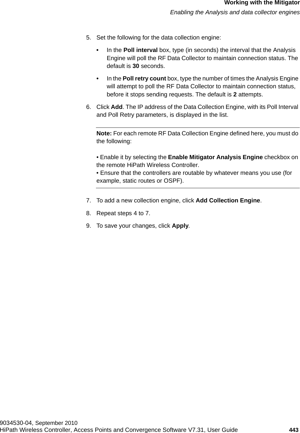
>
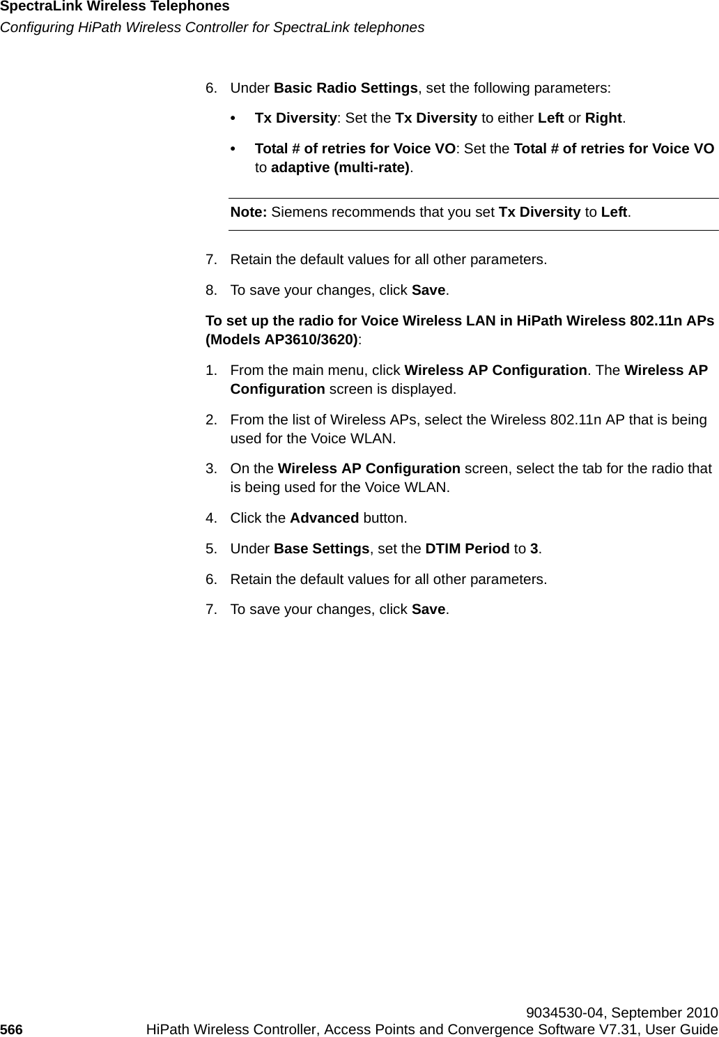
OAP36B User Manual
>
User Manual II
Contents
1.
User Manual I
2.
User Manual II
3.
User Manual
User Manual II
Navigation menu
Upload a User Manual
Namespaces
Wiki Guide
HTML
PDF
Info
Views
User Manual
Discussion / Help
Navigation

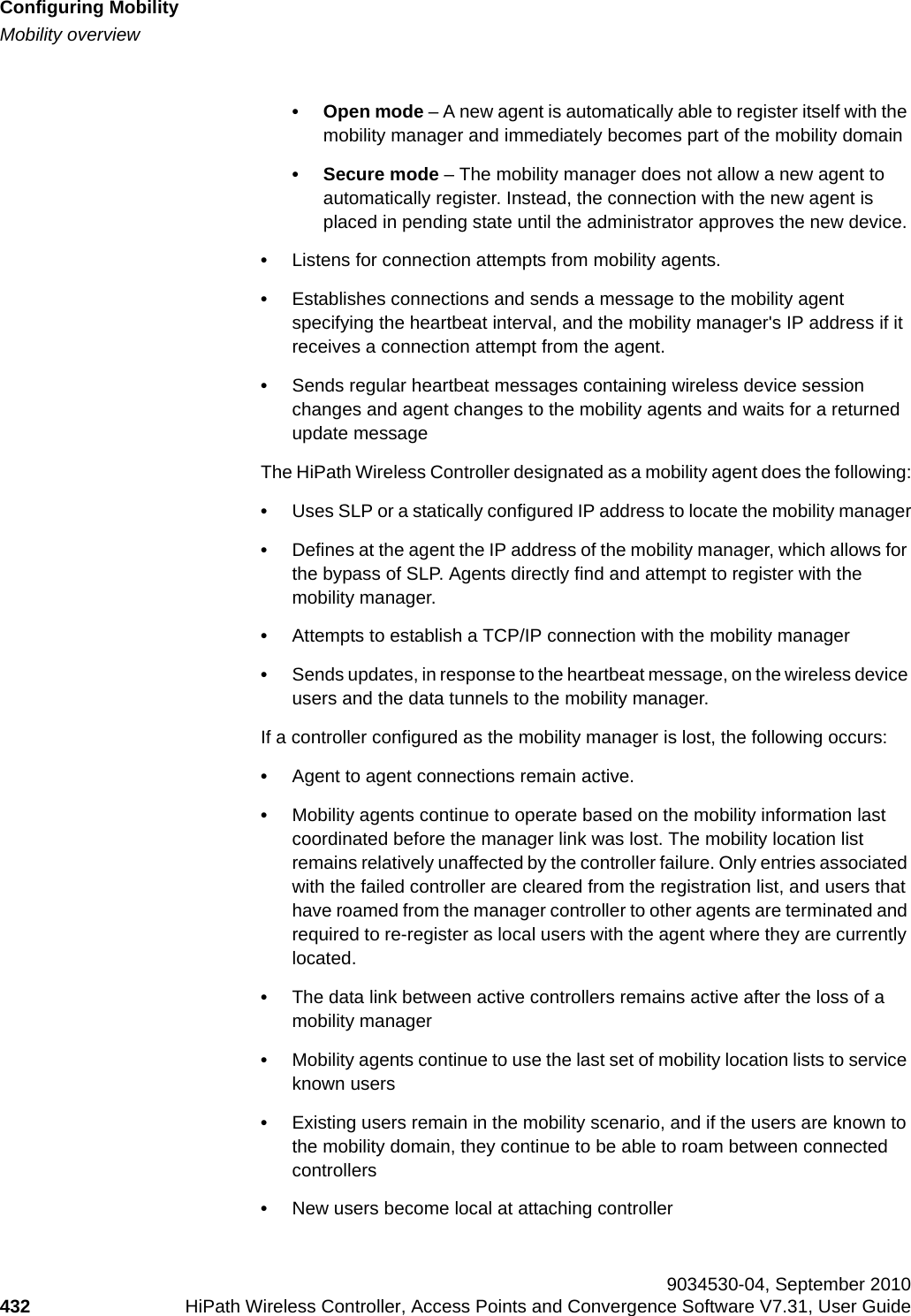

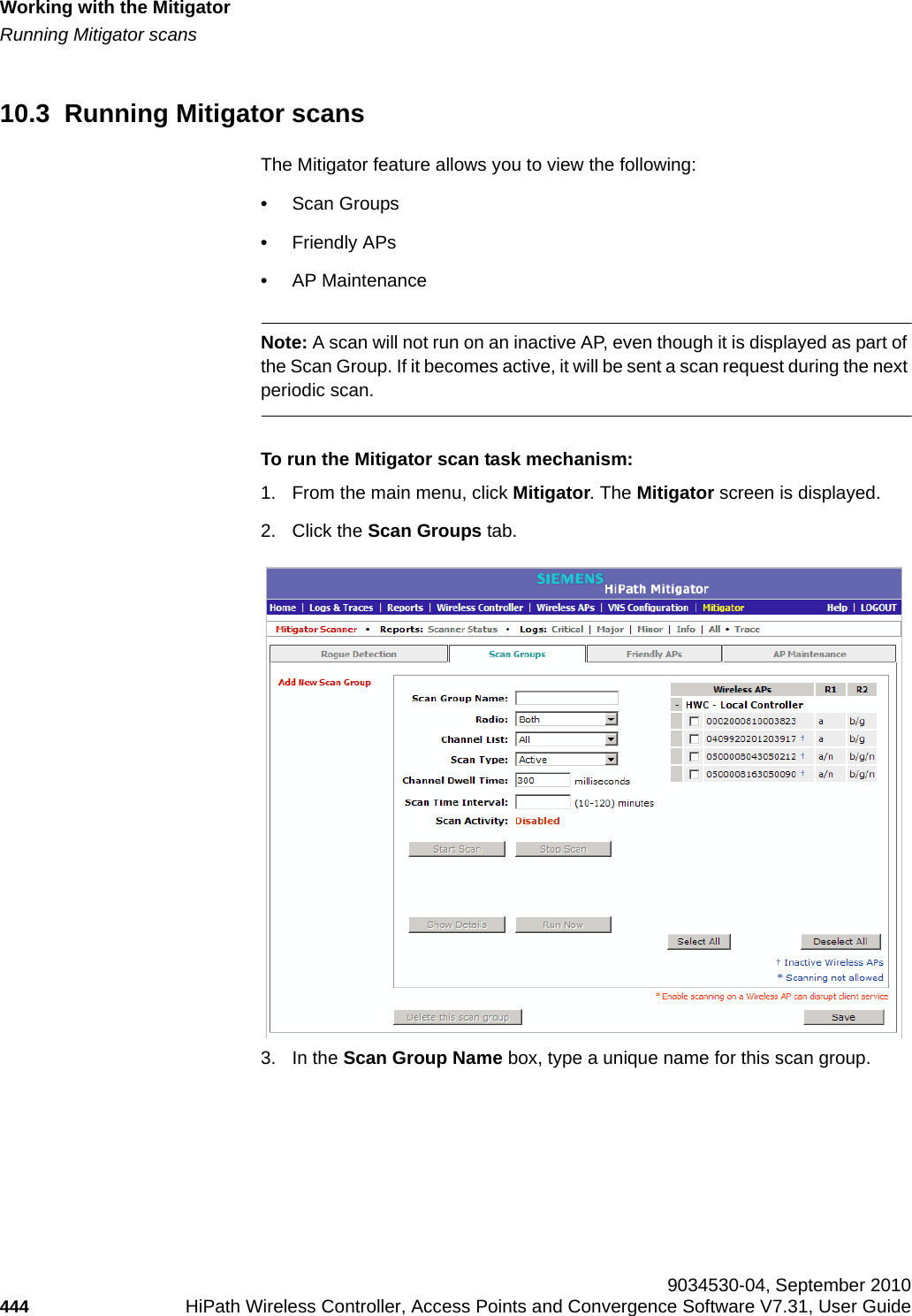
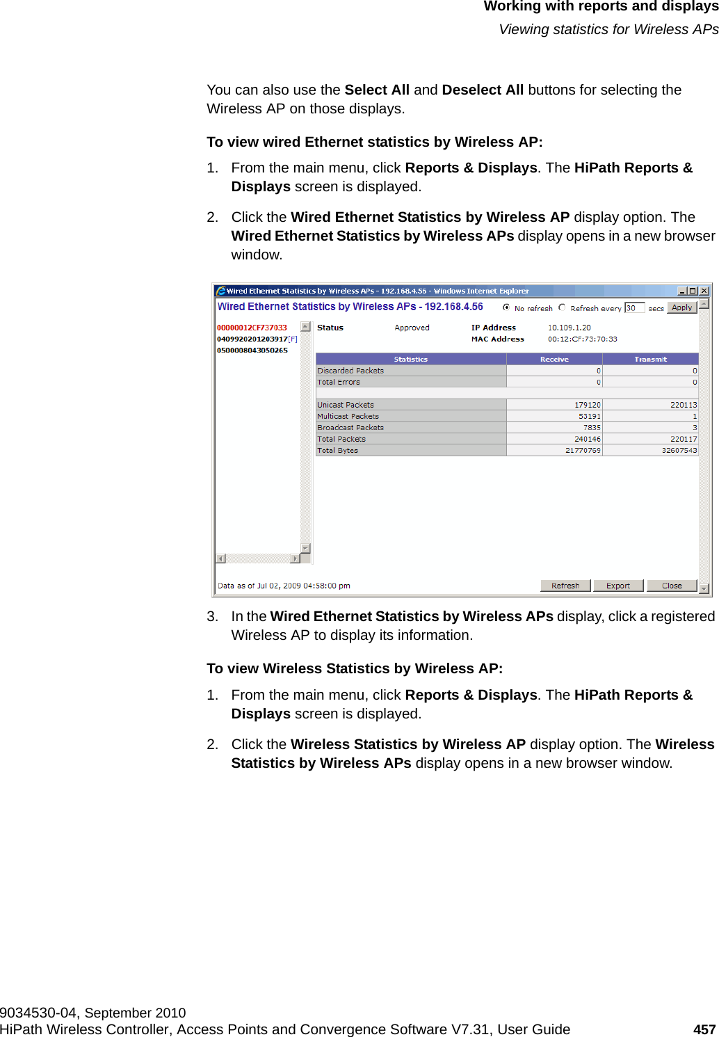

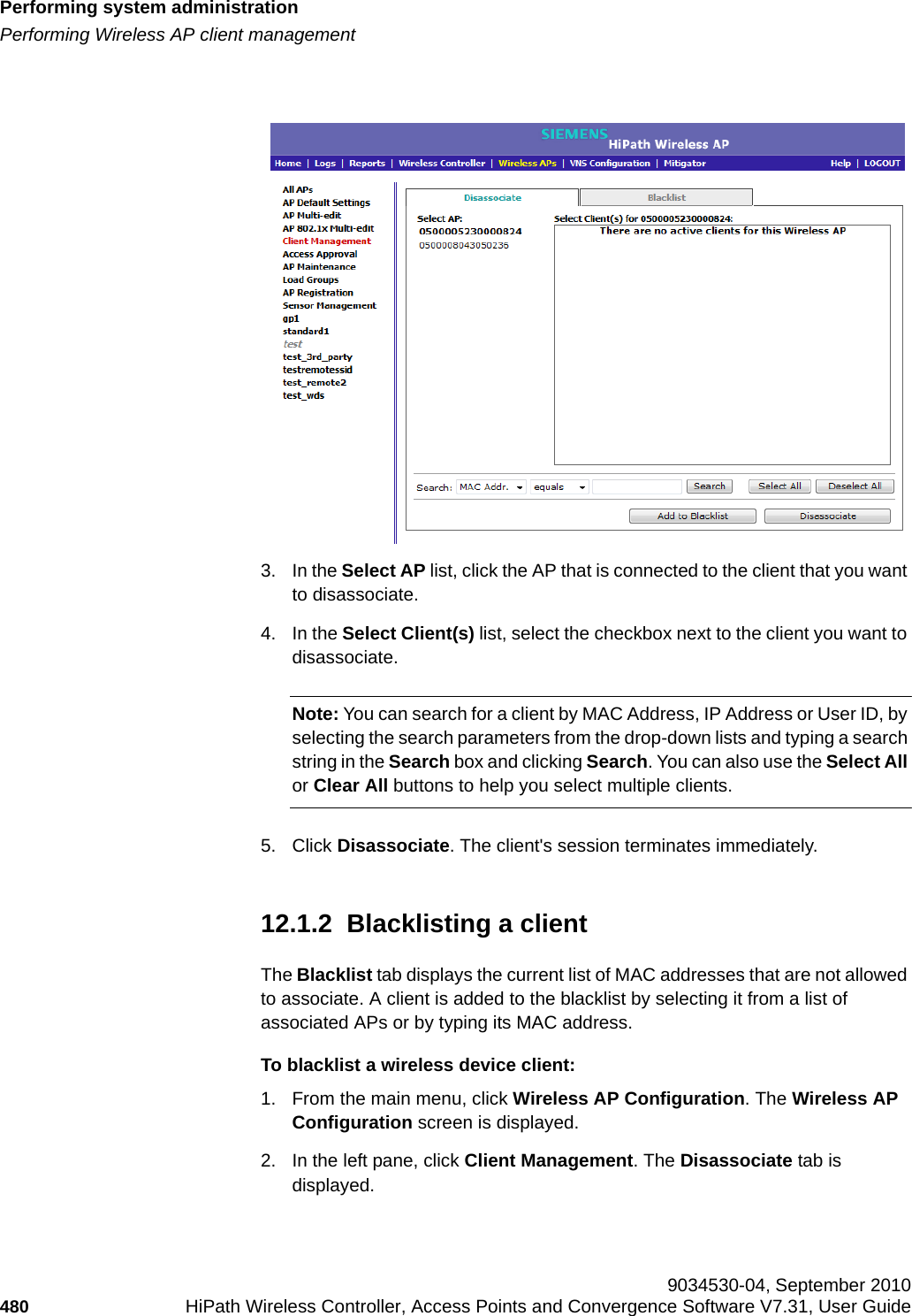
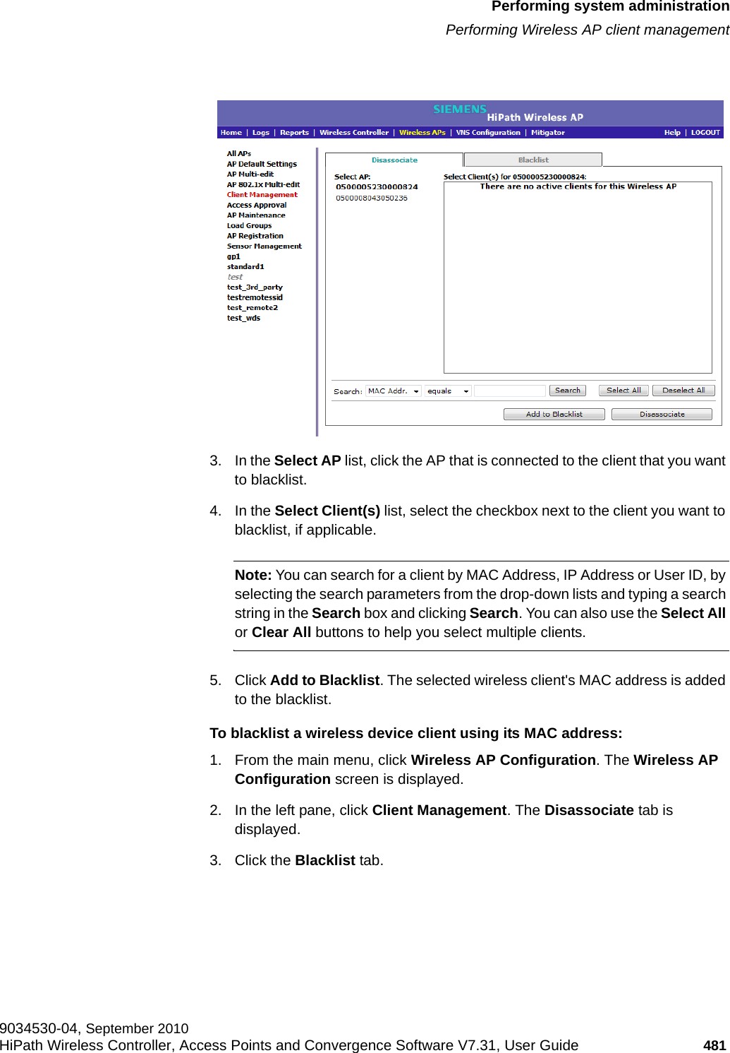
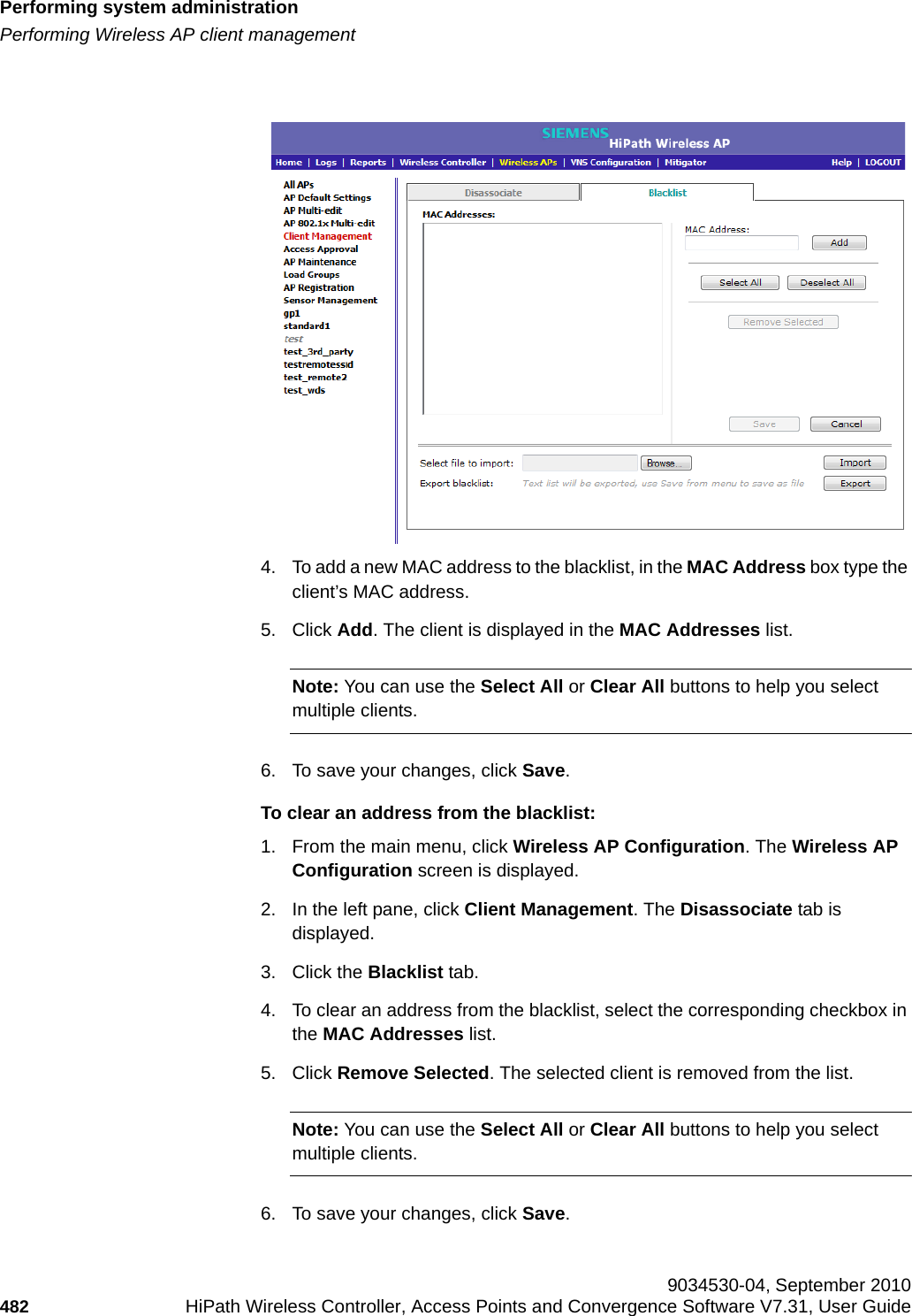
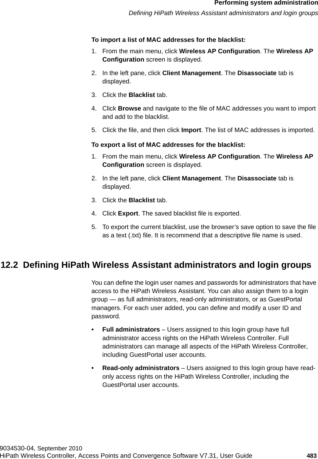
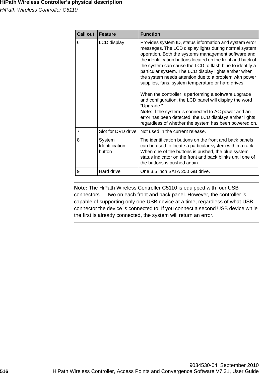
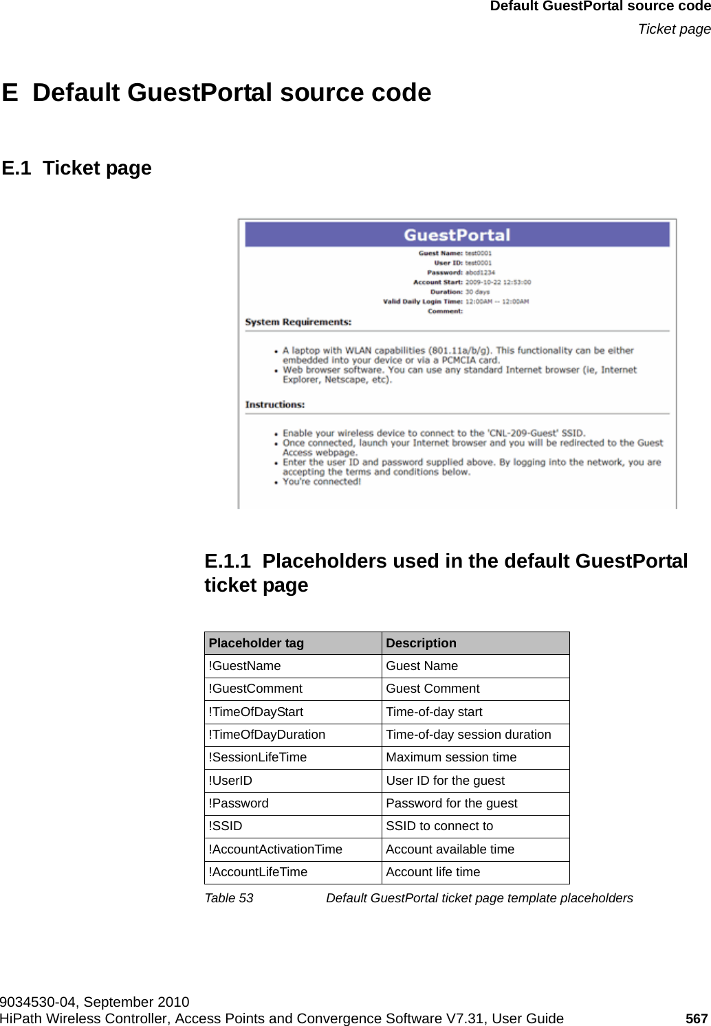
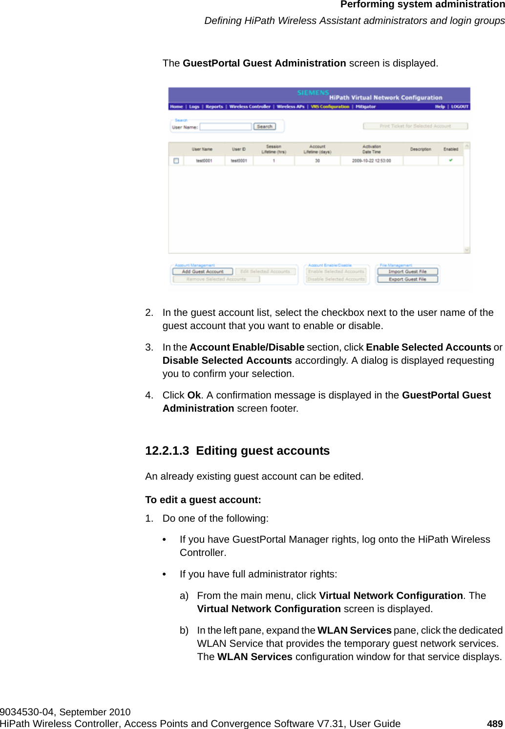
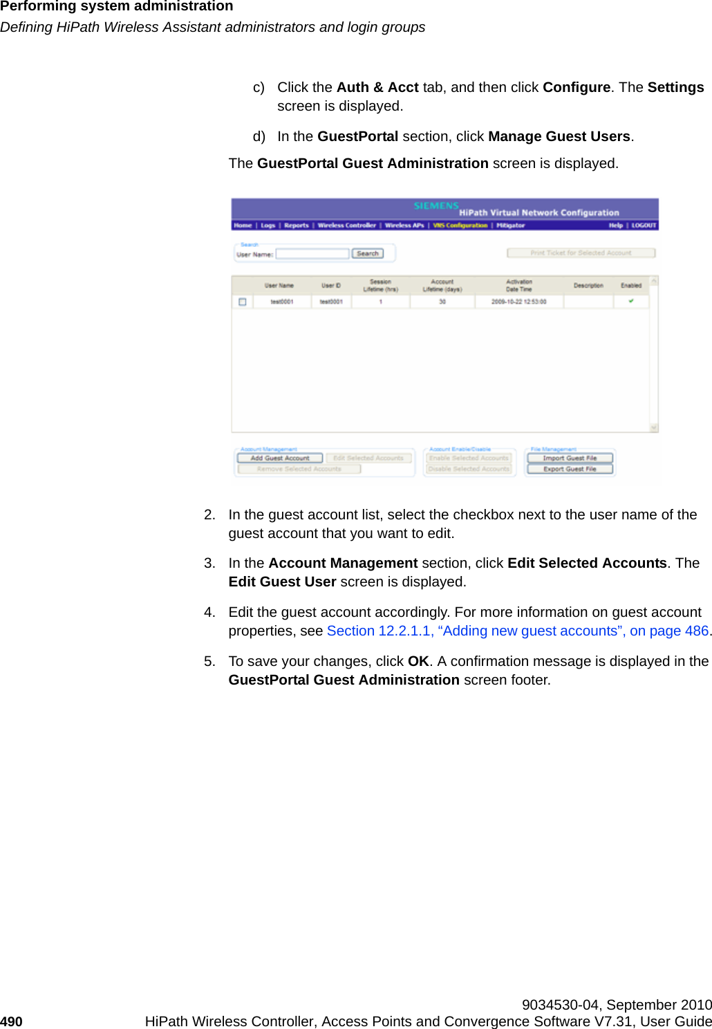
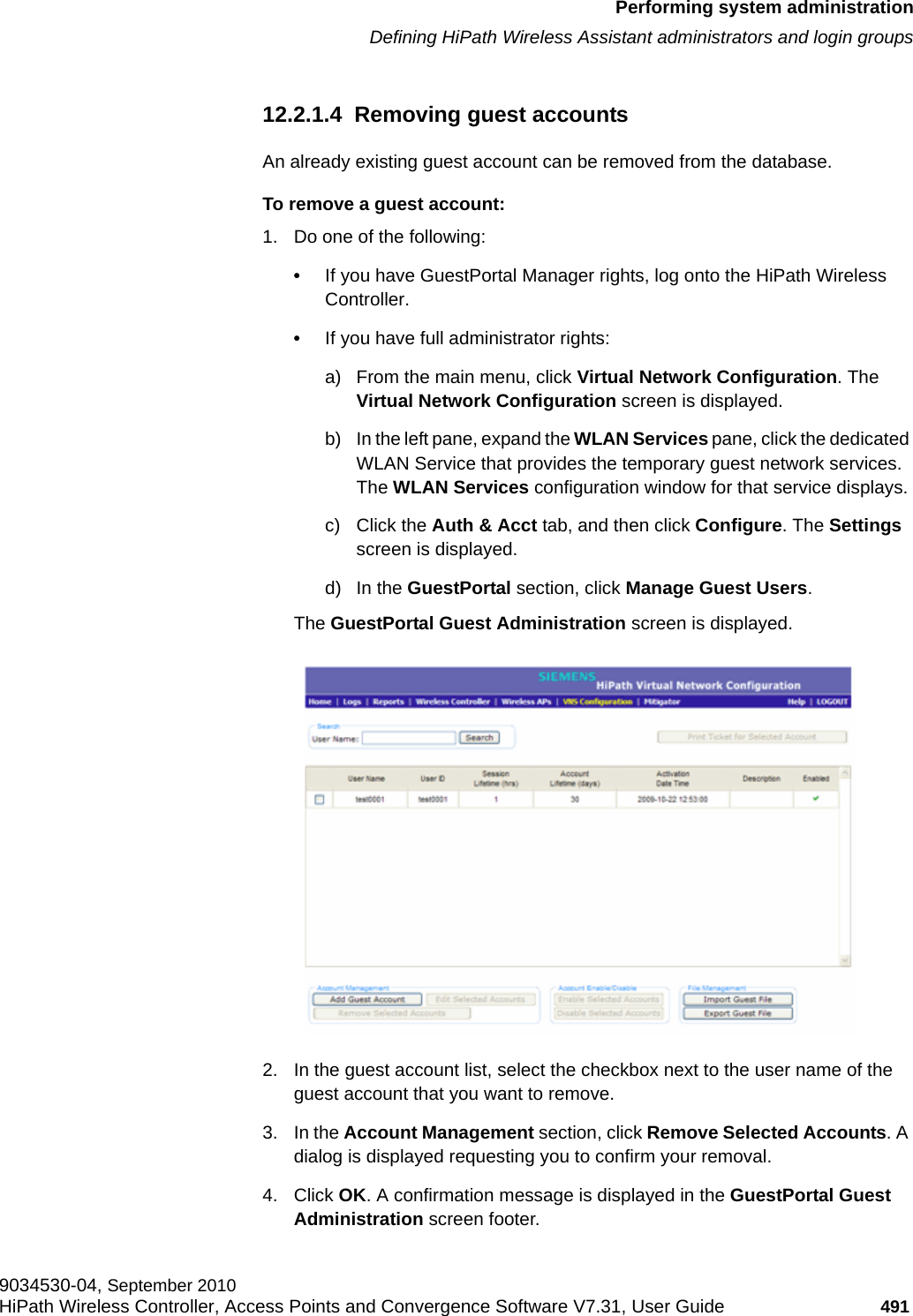
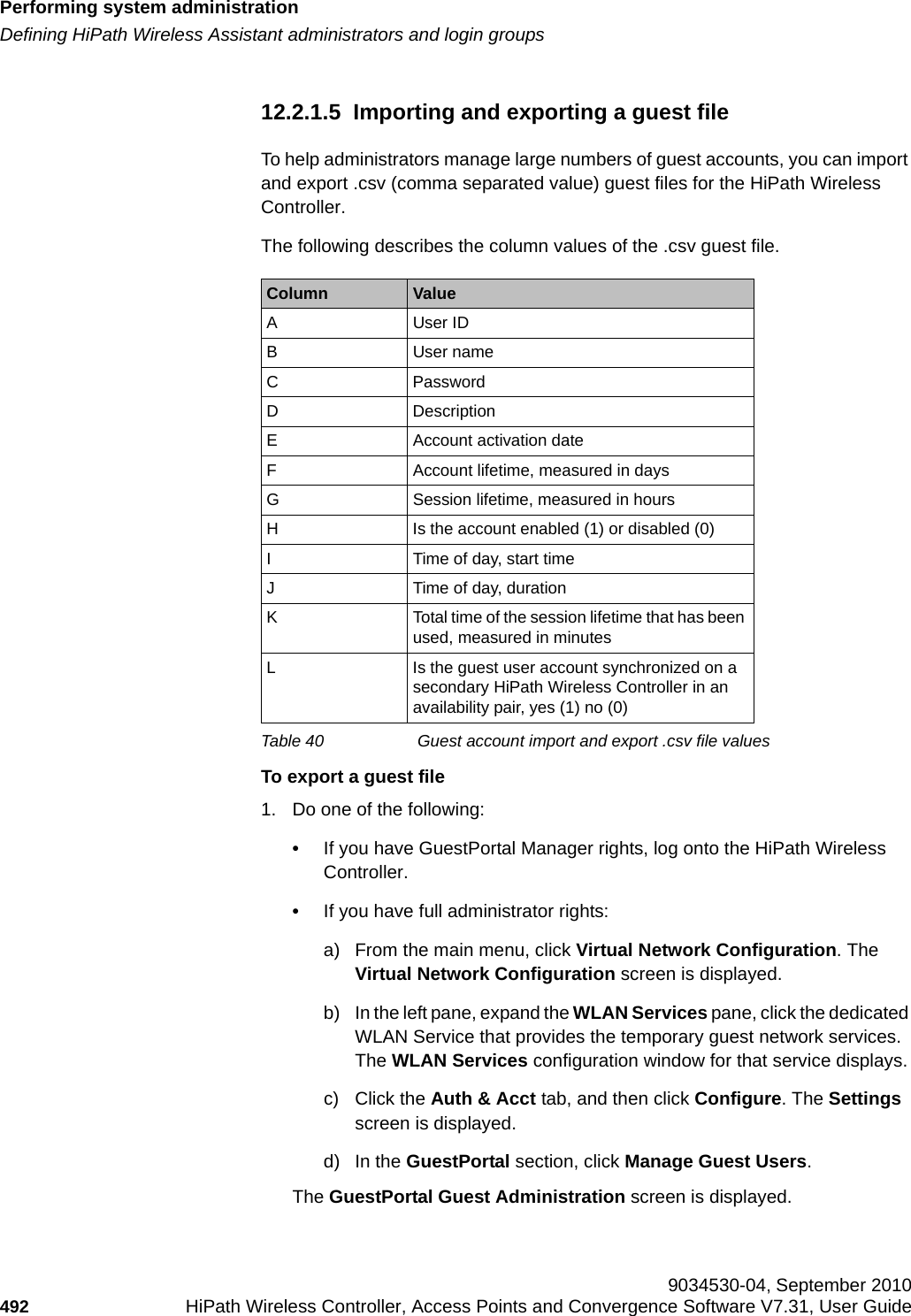
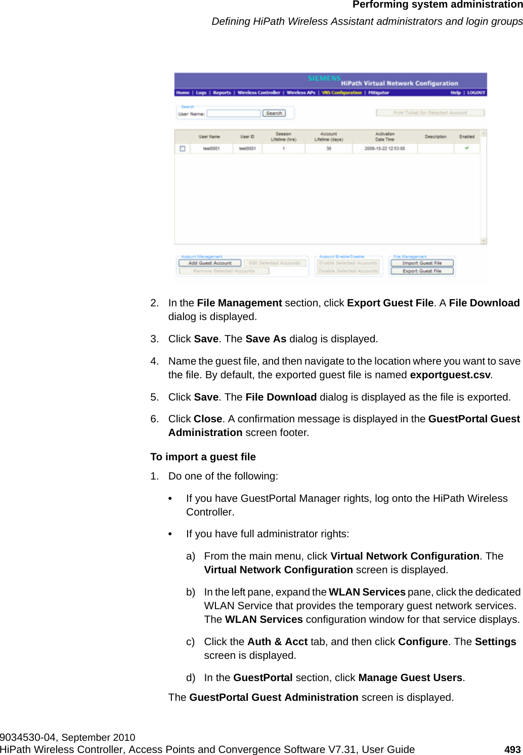
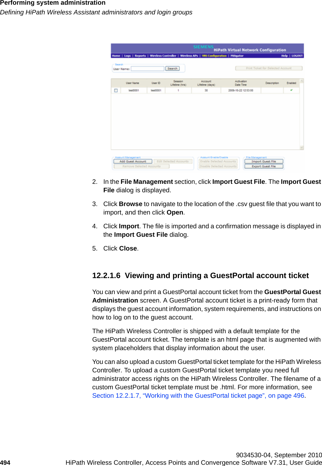
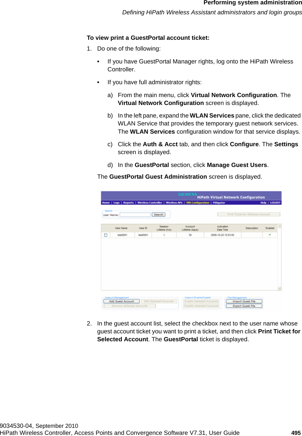
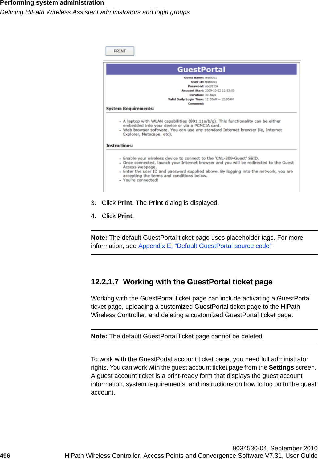
![Performing system administrationhwc_ongoing.fmDefining HiPath Wireless Assistant administrators and login groups 9034530-04, September 2010484 HiPath Wireless Controller, Access Points and Convergence Software V7.31, User Guide • GuestPortal managers – Users assigned to this login group can only manage GuestPortal user accounts. Any user who logs on to the HiPath Wireless Controller and is assigned to this group can only access the GuestPortal Guest Administration page of the HiPath Wireless Assistant. Note: When adding or modifying a user, note the following password character constraints:• Allowed characters include A-Z a-z 0-9 ~!@#$%^&*()_+|-=\{}[];<>?,.• Characters not allowed include / ` ' " : and space is not valid.To add a HiPath Wireless Controller administrator to a login group:1. From the main menu, click Wireless Controller Configuration. The Wireless Controller Configuration screen is displayed.2. In the left pane, click Login Management. The Local Authentication tab is displayed.3. In the Group drop-down list, click one of the following:• Full Administrator – Users assigned to this login group have full administrator access rights on the HiPath Wireless Controller. Full administrators can manage GuestPortal user accounts.• Read-only Administrator – Users assigned to this login group have read-only access rights on the HiPath Wireless Controller.Read-only administrators have read access to the GuestPortal user accounts.](https://usermanual.wiki/Extreme-Networks/OAP36B.User-Manual-II/User-Guide-1395764-Page-56.png)
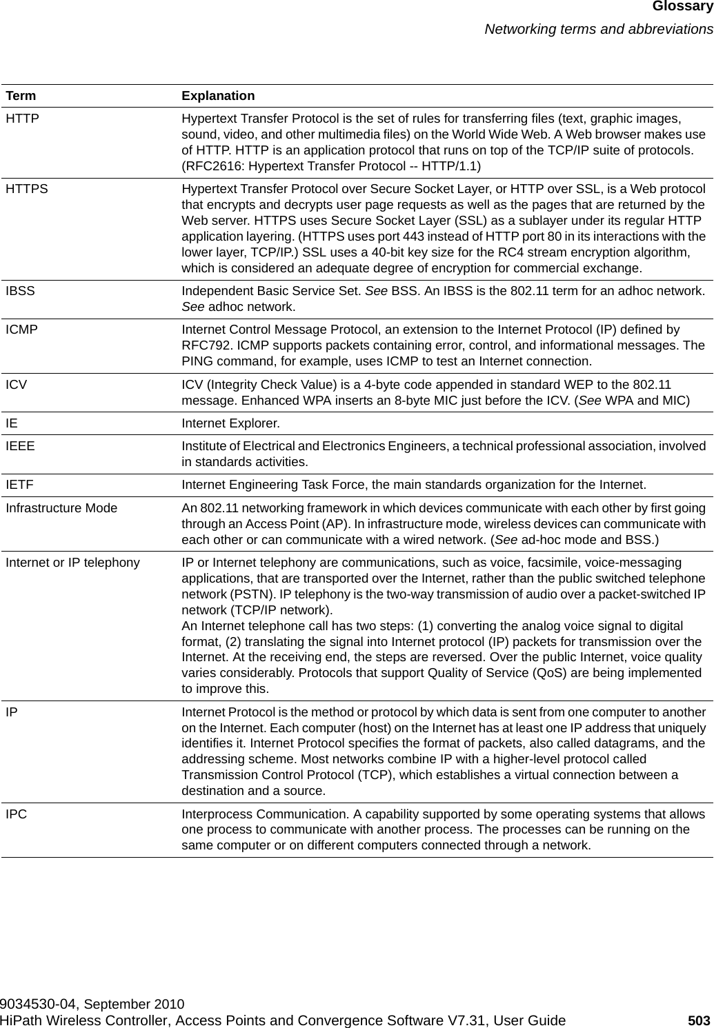
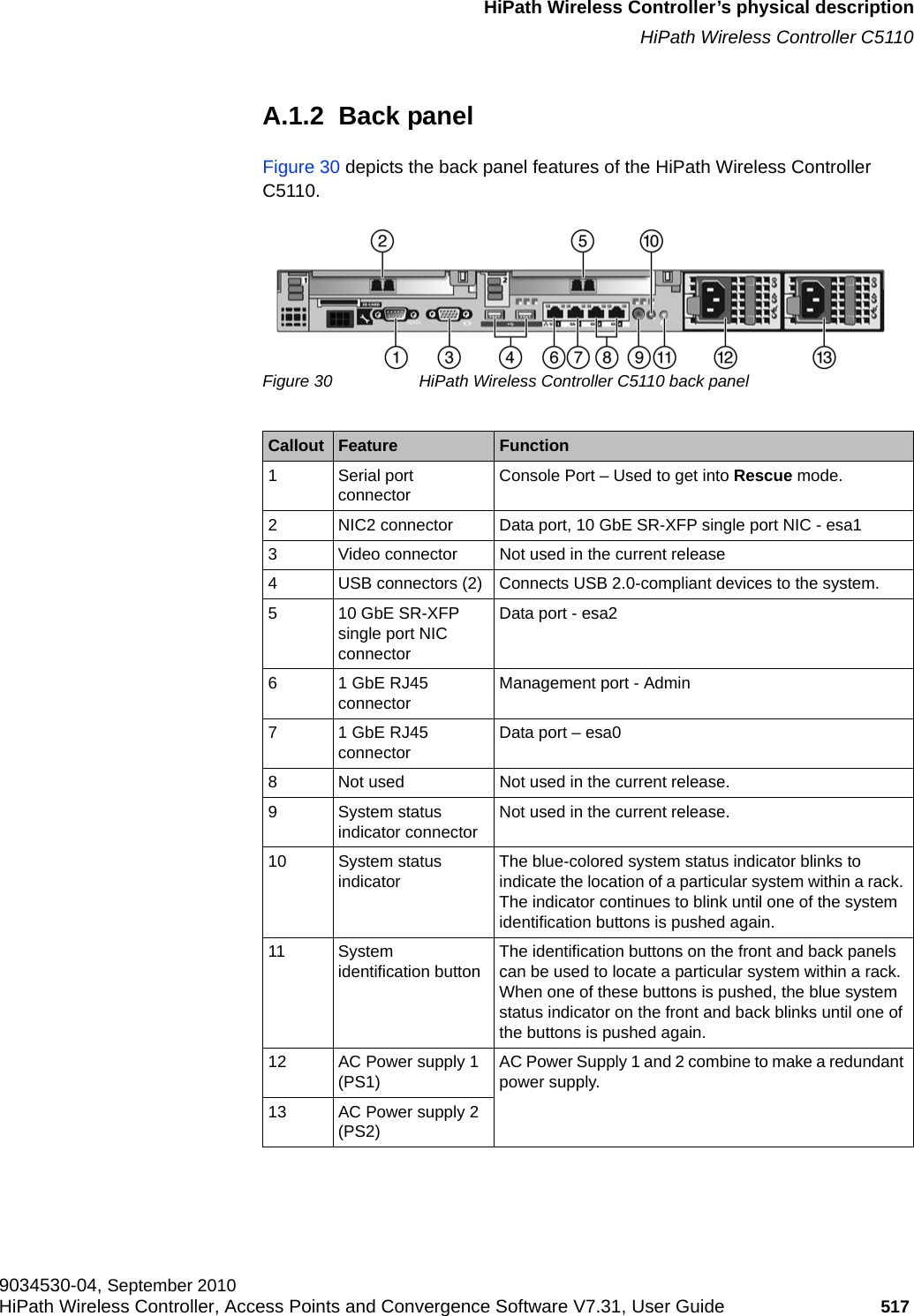
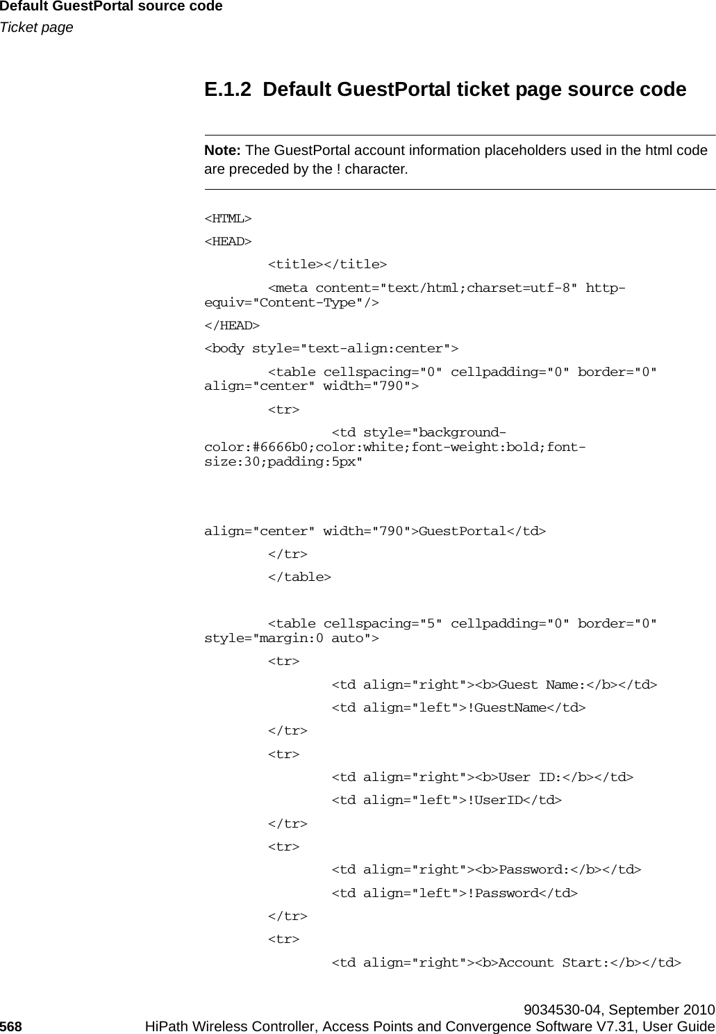
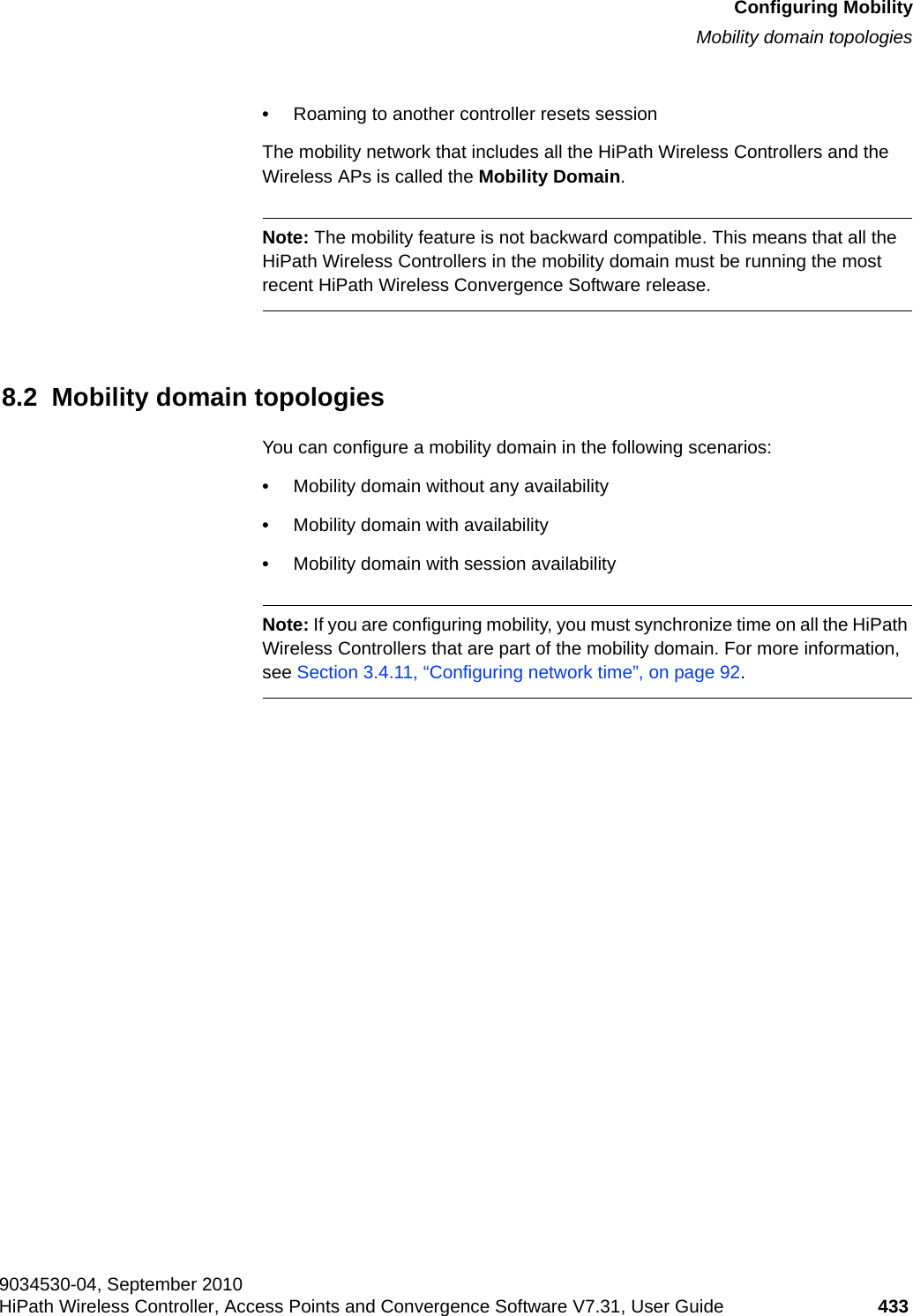
![Glossaryhwc_glossary.fmNetworking terms and abbreviations 9034530-04, September 2010502 HiPath Wireless Controller, Access Points and Convergence Software V7.31, User Guide ELA (OPSEC) Event Logging API (Application Program Interface) for OPSEC, a module in Check Point used to enable third-party applications to log events into the Check Point VPN-1/FireWall-1 management system. Encapsulation See tunnelling.ESS Extended Service Set (ESS). Several Basic Service Sets (BSSs) can be joined together to form one logical WLAN segment, referred to as an extended service set (ESS). The SSID is used to identify the ESS. (See BSS and SSID.)FHSS Frequency-Hopping Spread Spectrum. A transmission technology used in Local Area Wireless Network (LAWN) transmissions where the data signal is modulated with a narrowband carrier signal that ‘hops’ in a random but predictable sequence from frequency to frequency as a function of time over a wide band of frequencies. This technique reduces interference. If synchronized properly, a single logical channel is maintained. (Compare DSSS)Fit, thin and fat APs A thin AP architecture uses two components: an access point that is essentially a stripped-down radio and a centralized management controller that handles the other WLAN system functions. Wired network switches are also required. A fit AP, a variation of the thin AP, handles the RF and encryption, while the central management controller, aware of the wireless users' identities and locations, handles secure roaming, quality of service, and user authentication. The central management controller also handles AP configuration and management. A fat (or thick) AP architecture concentrates all the WLAN intelligence in the access point. The AP handles the radio frequency (RF) communication, as well as authenticating users, encrypting communications, secure roaming, WLAN management, and in some cases, network routing. FQDN Fully Qualified Domain Name. A ‘friendly’ designation of a computer, of the general form computer.[subnetwork.].organization.domain. The FQDN names must be translated into an IP address in order for the resource to be found on a network, usually performed by a Domain Name Server.FTM Forwarding Table ManagerFTP File Transfer ProtocolGateway In the wireless world, an access point with additional software capabilities such as providing NAT and DHCP. Gateways may also provide VPN support, roaming, firewalls, various levels of security, etc. Gigabit Ethernet The high data rate of the Ethernet standard, supporting data rates of 1 gigabit (1,000 megabits) per second.GUI Graphical User InterfaceHeartbeat message A heartbeat message is a UDP data packet used to monitor a data connection, polling to see if the connection is still alive.In general terms, a heartbeat is a signal emitted at regular intervals by software to demonstrate that it is still alive. In networking, a heartbeat is the signal emitted by a Level 2 Ethernet transceiver at the end of every packet to show that the collision-detection circuit is still connected.Host (1) A computer (usually containing data) that is accessed by a user working on a remote terminal, connected by modems and telephone lines. (2) A computer that is connected to a TCP/IP network, including the Internet. Each host has a unique IP address.Term Explanation](https://usermanual.wiki/Extreme-Networks/OAP36B.User-Manual-II/User-Guide-1395764-Page-74.png)