Essence Security ES800TR5 Tag reader User Manual We R System
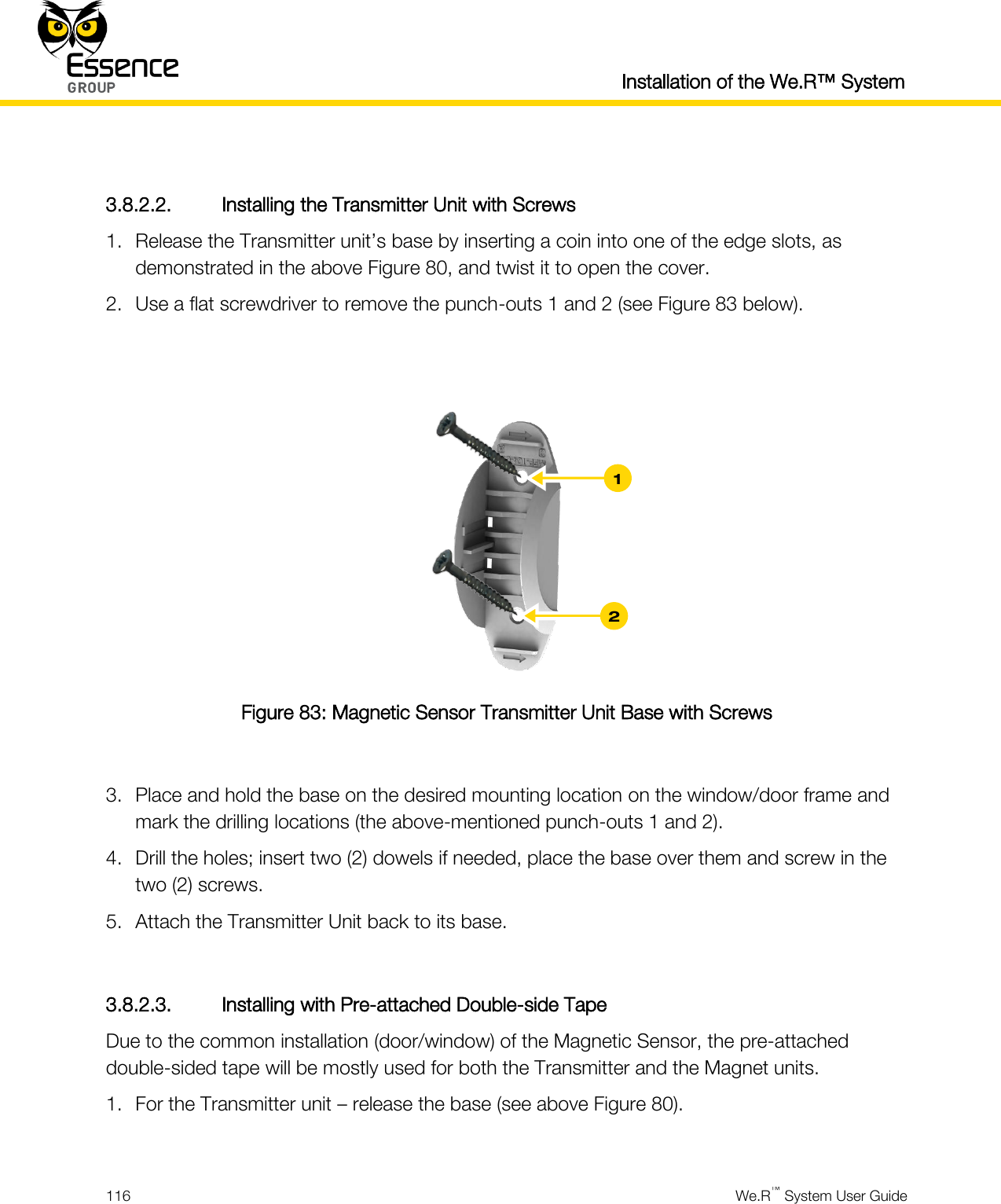
Essence Security International ltd. Tag reader We R System
Contents
- 1. User manual_24733FL_part5
- 2. User manual _24733SK2_part6
- 3. User manual _24733UT_part7
- 4. User manual _24734_part1
- 5. User manual _24734_part2
- 6. User manual _24734_part3
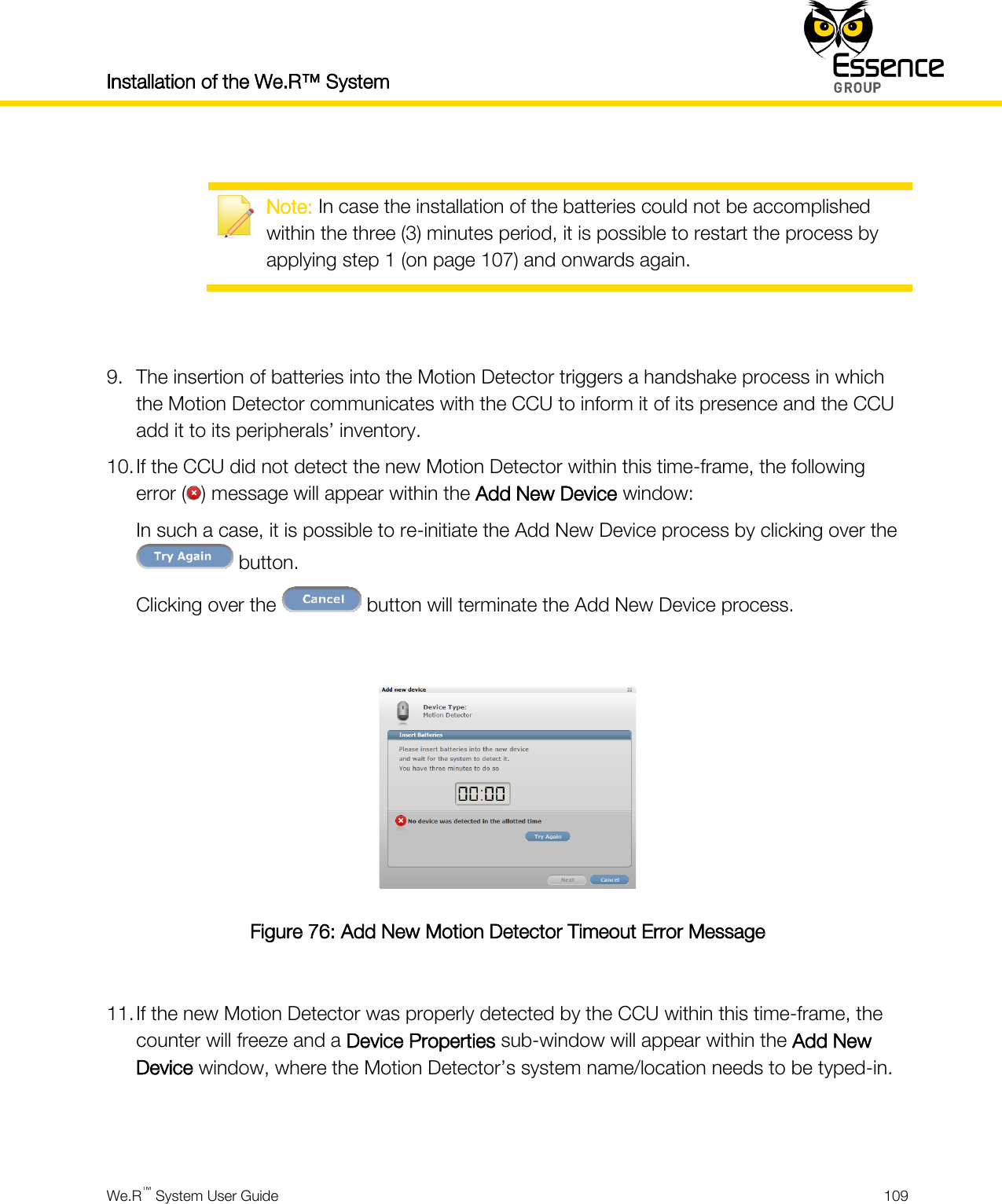
- 7. User manual _24734_part8
- 8. User manual _24734TR5_part4
- 9. User manual_24733SK2_part6
- 10. User manual_24733UT_part7
- 11. User manual_24734_part1
- 12. User manual_24734_part2
- 13. User manual_24734_part3
- 14. User manual_24734_part8
- 15. User manual_24734TR5_part4
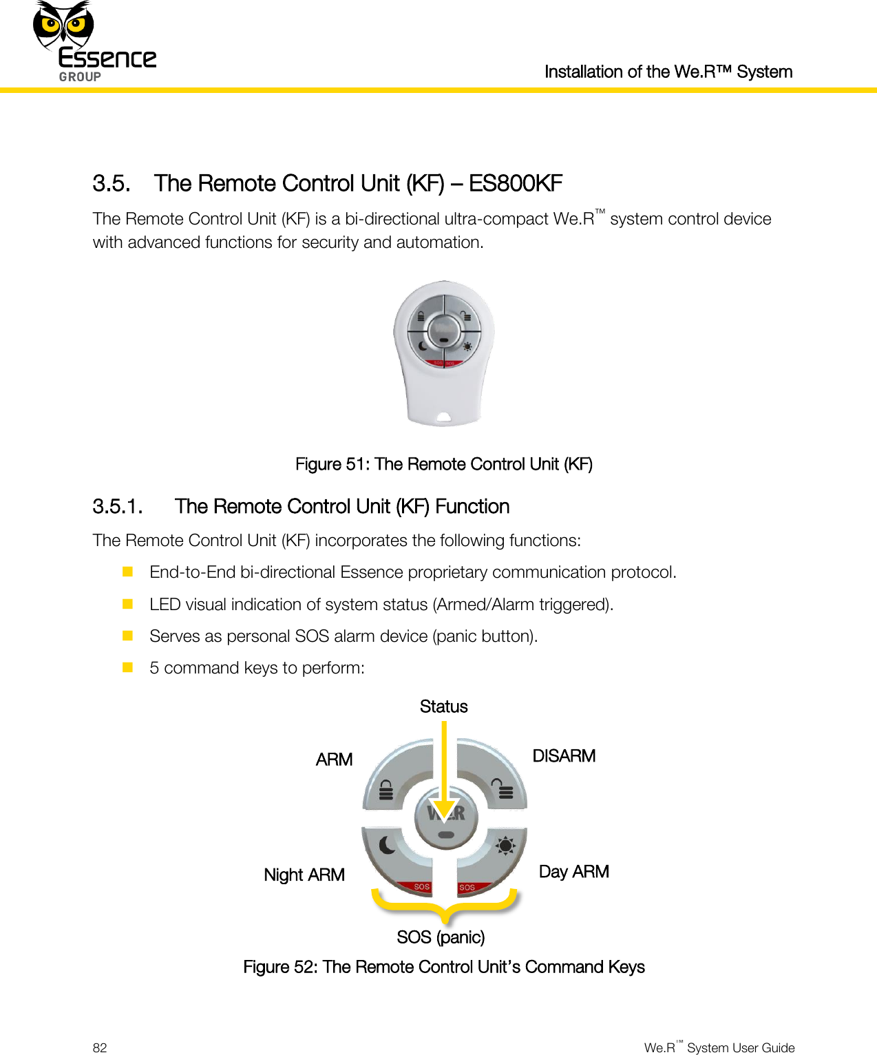
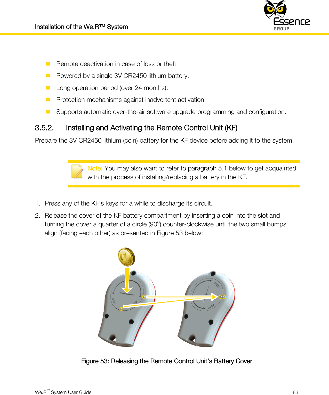
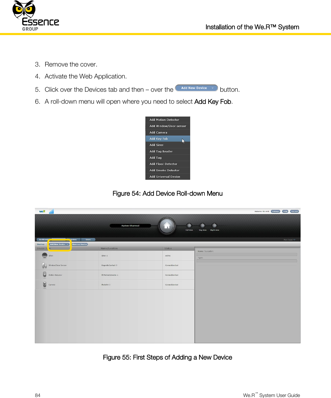
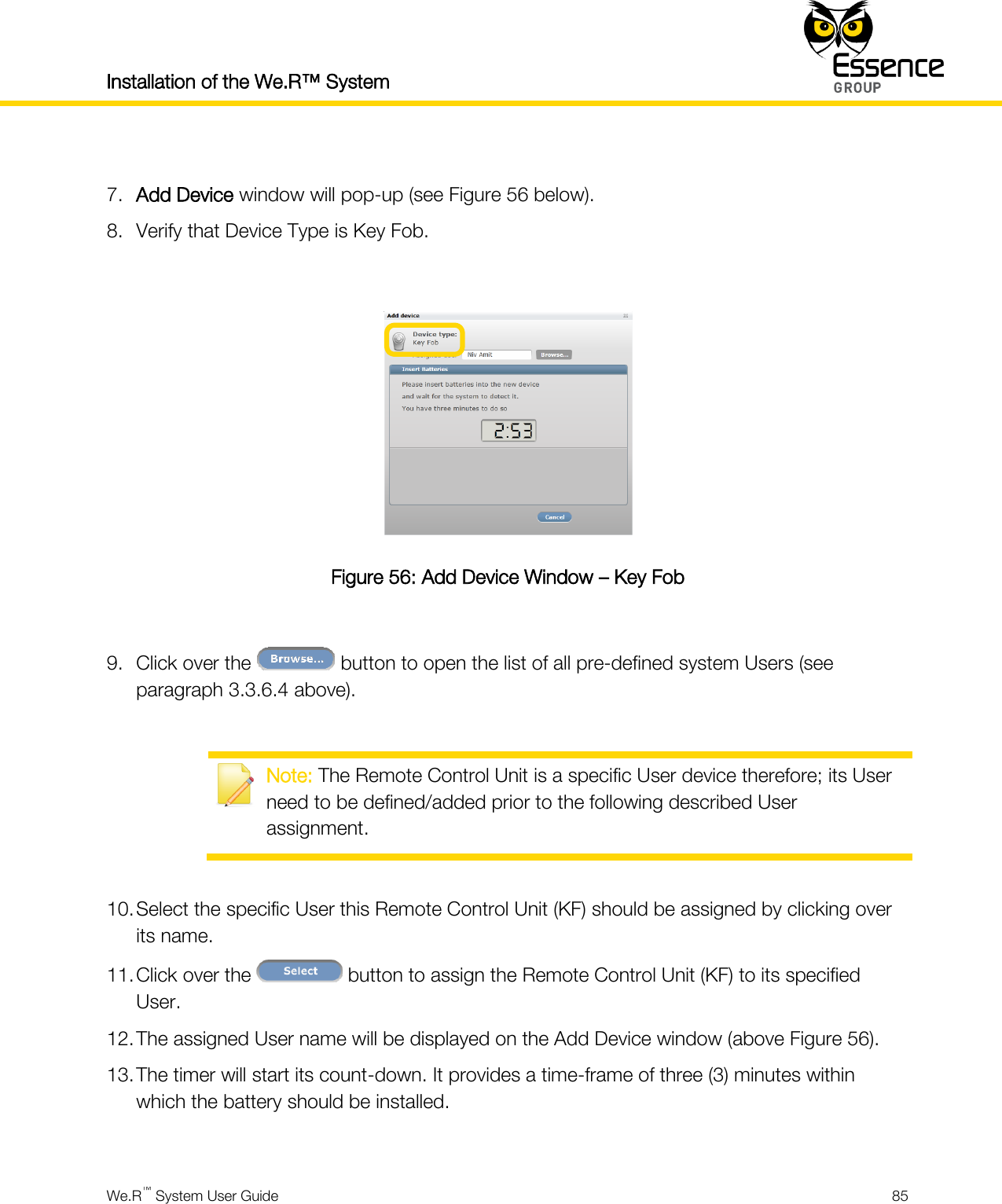
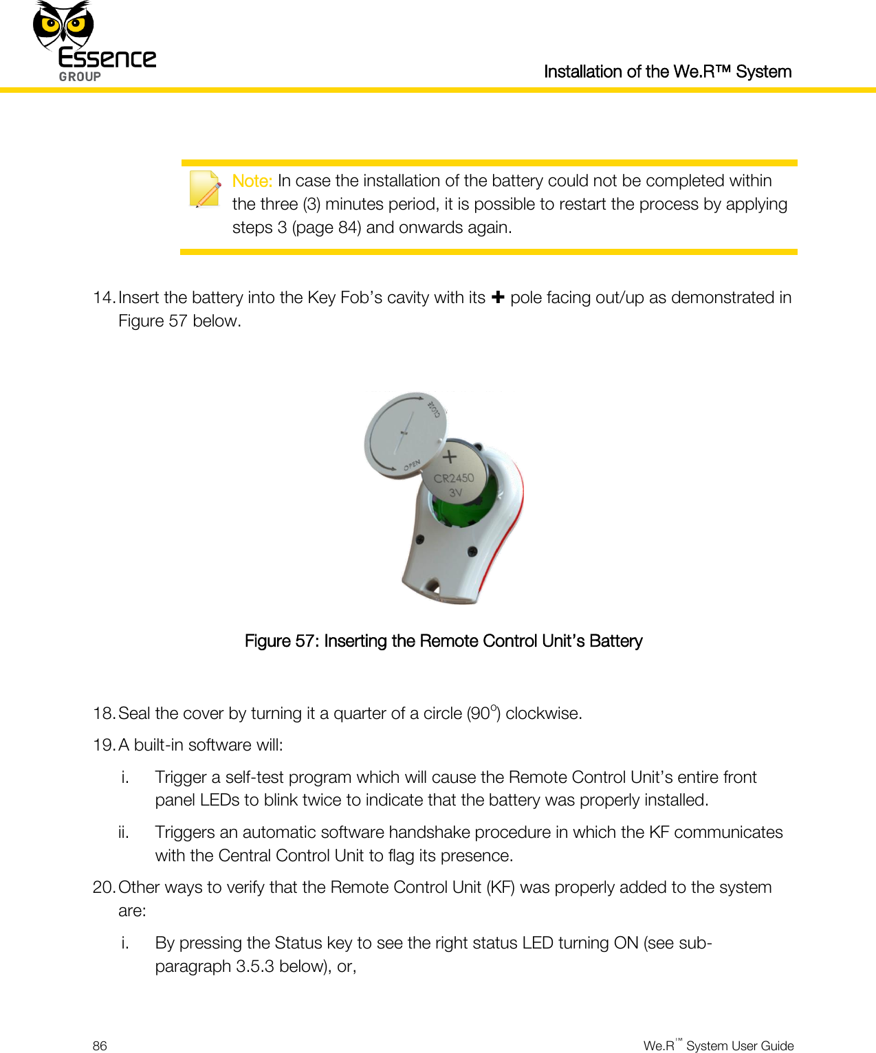
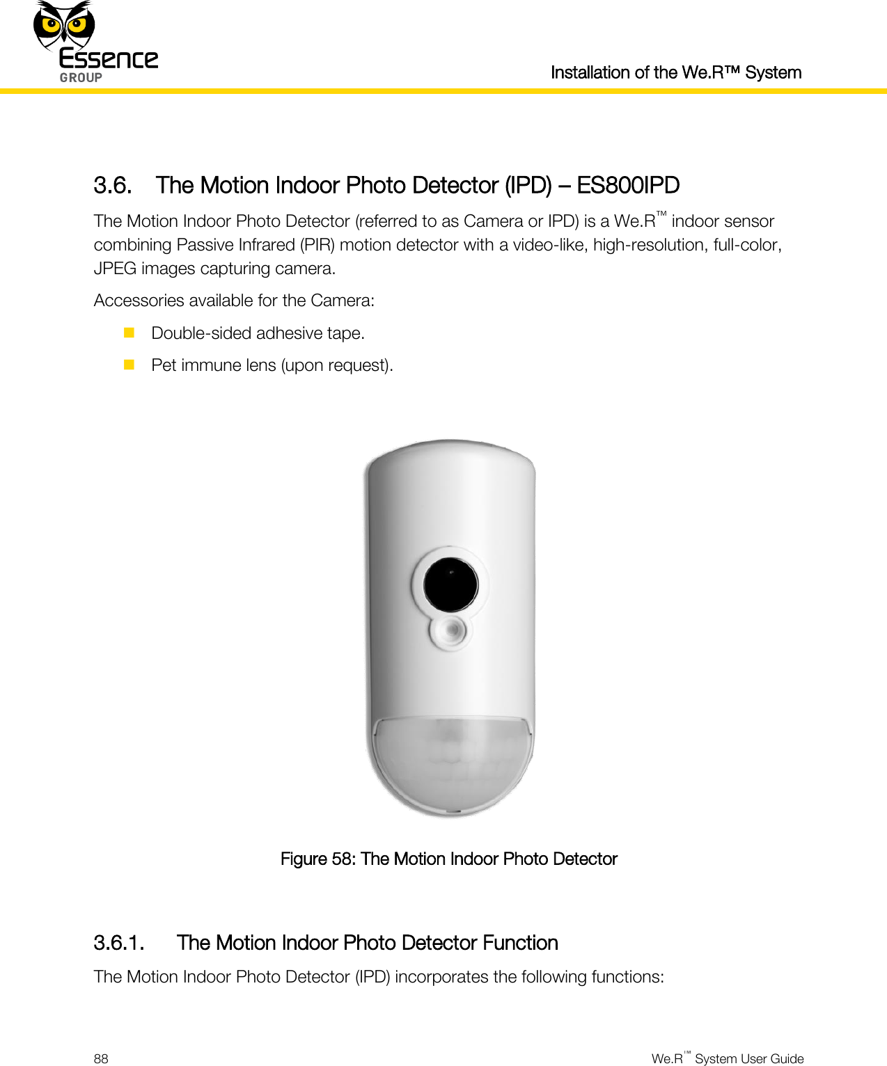
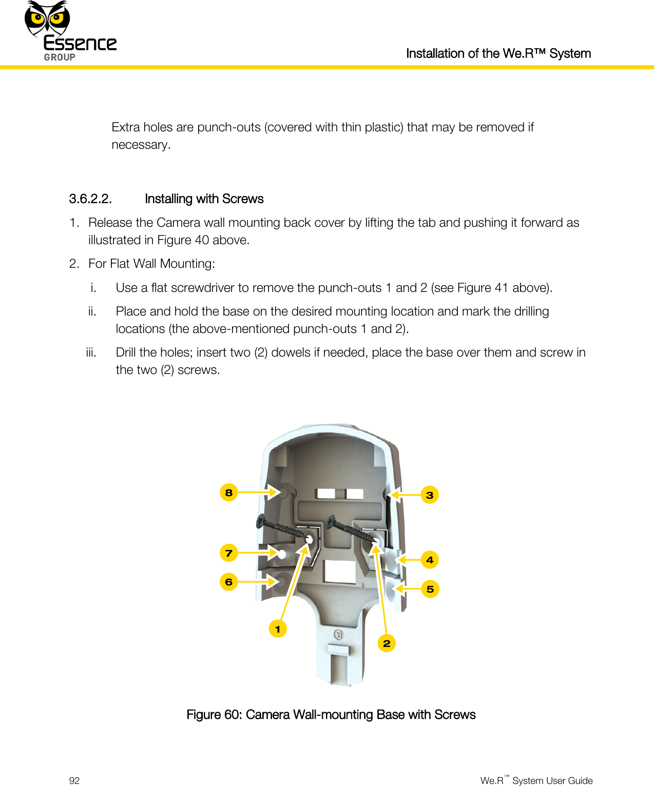
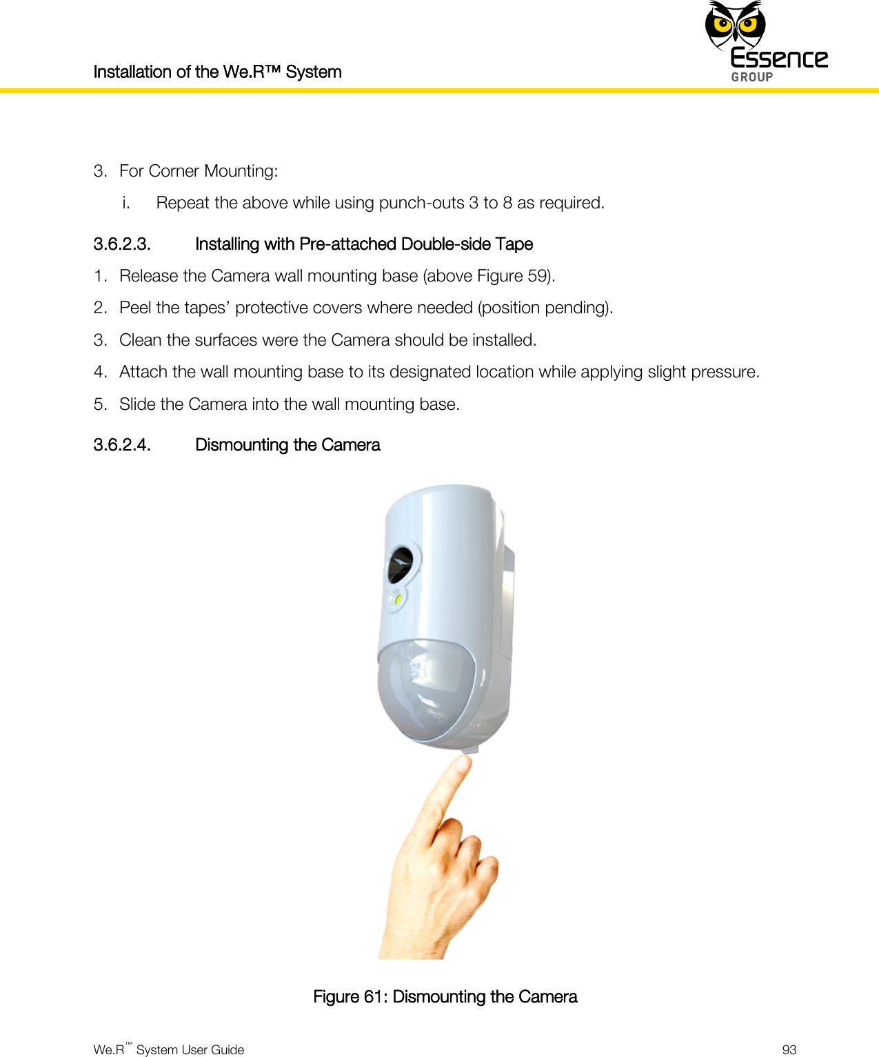
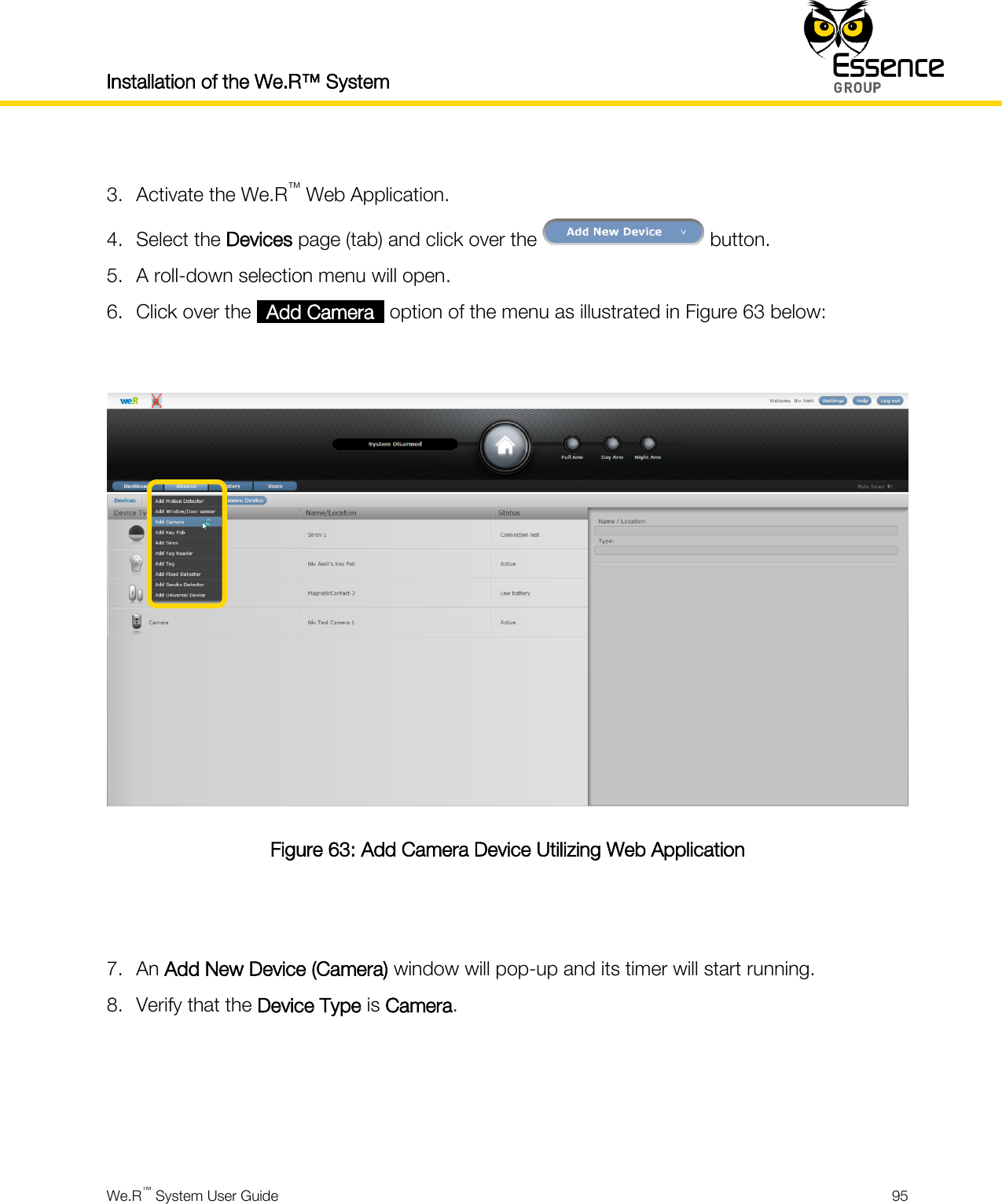
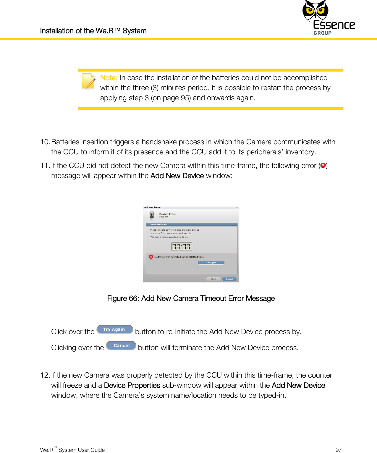
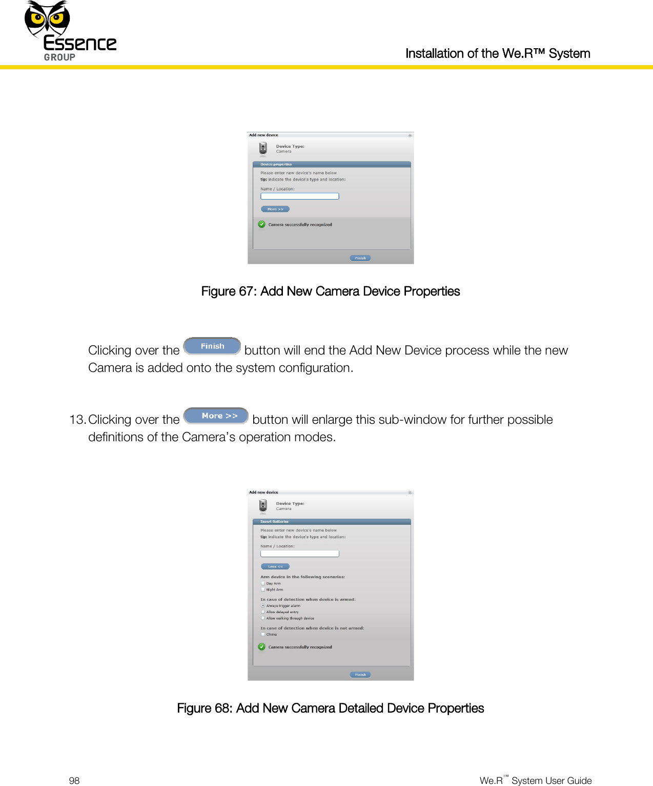
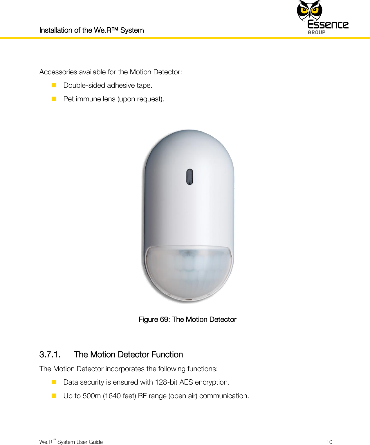
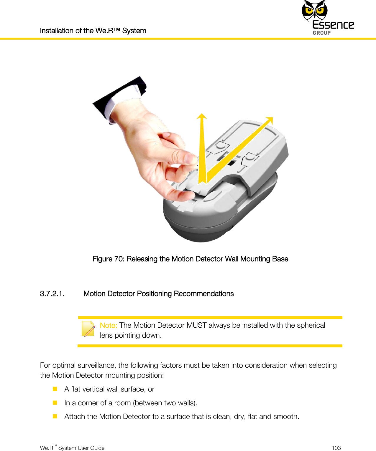
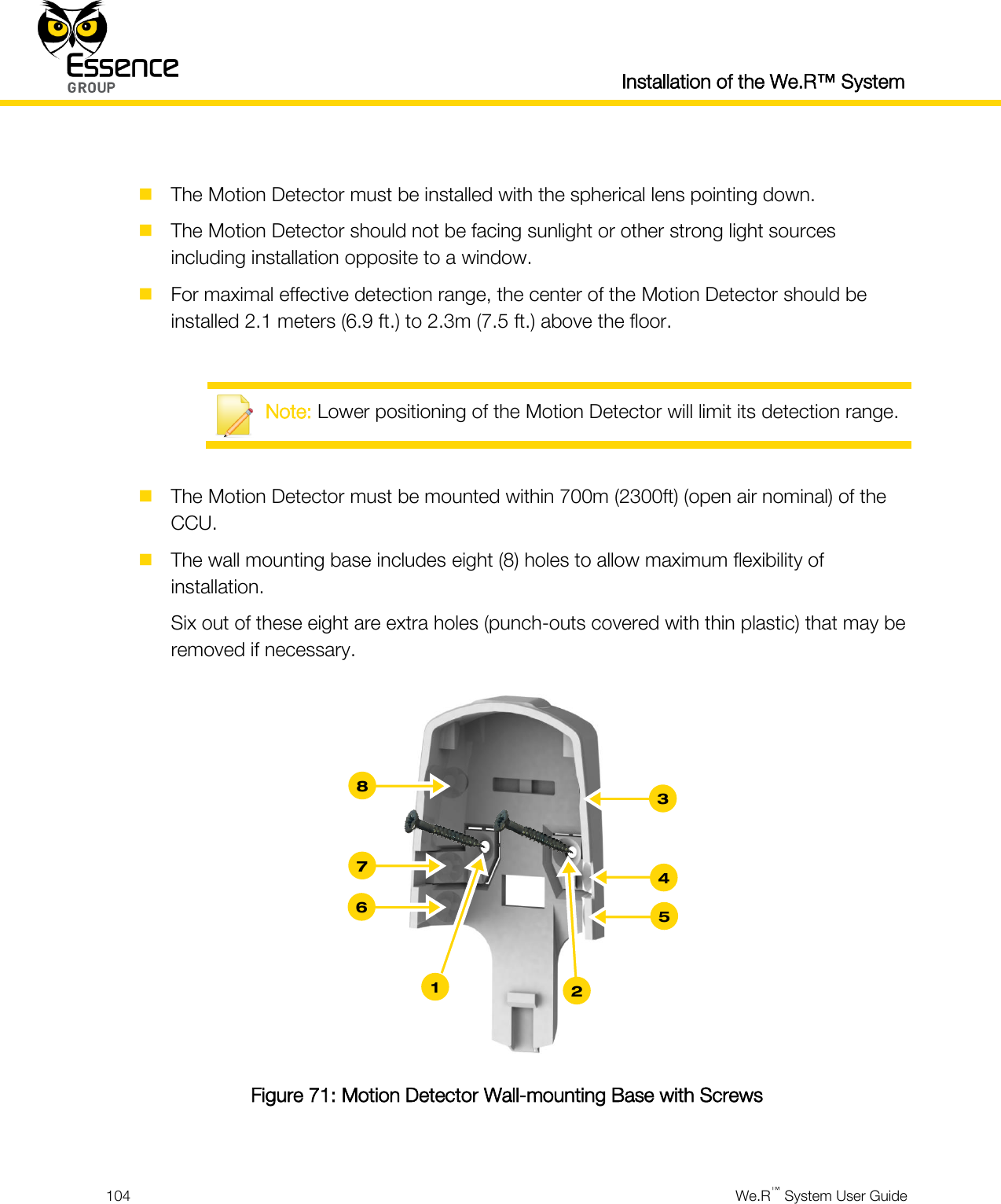
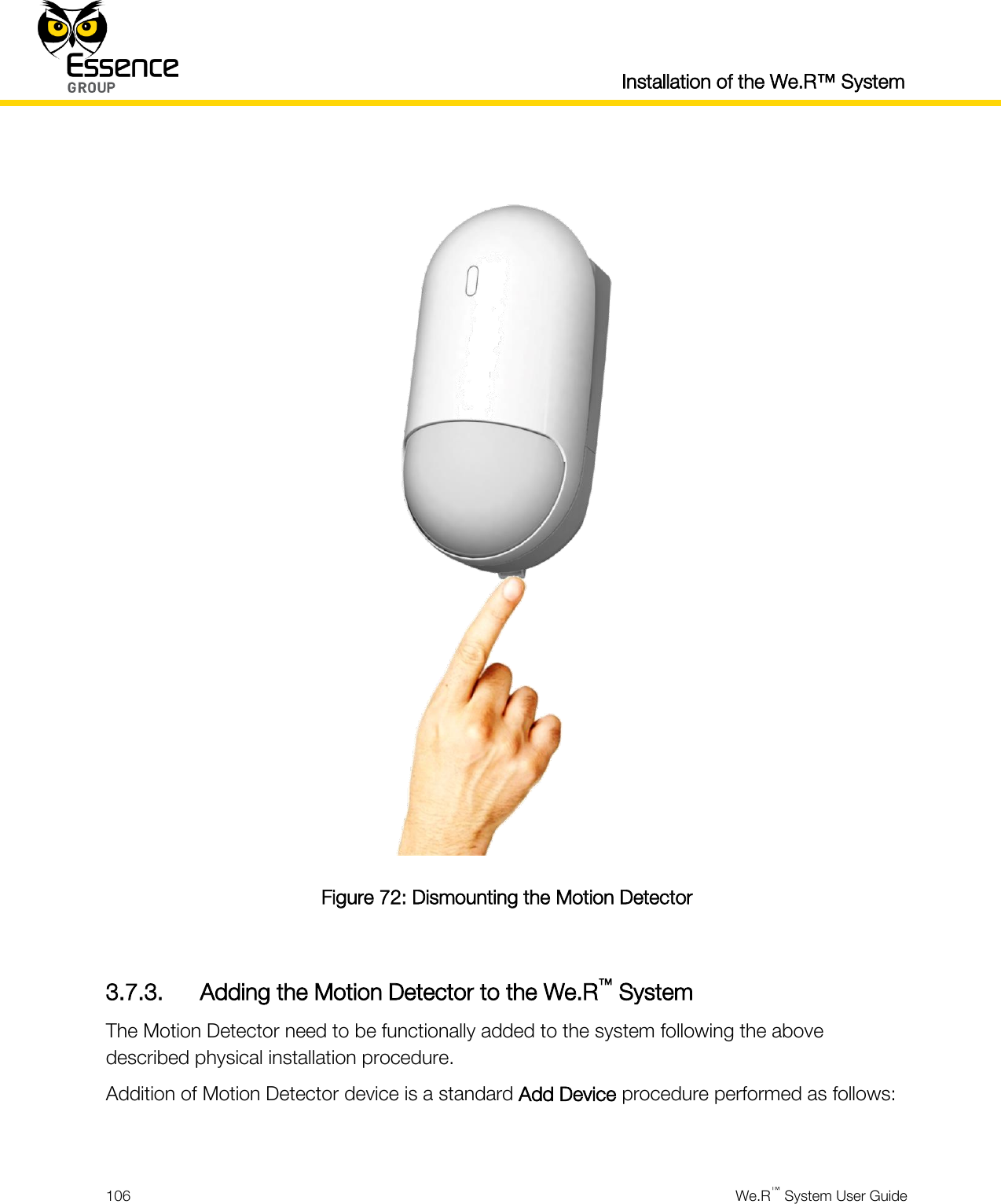
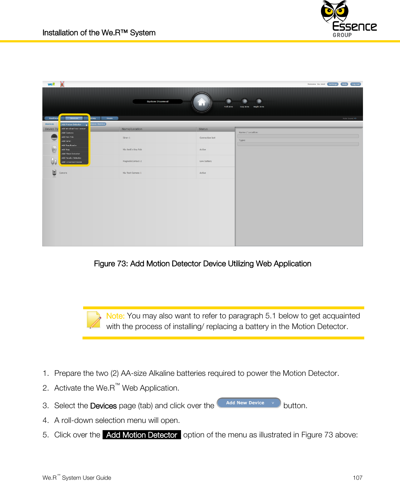
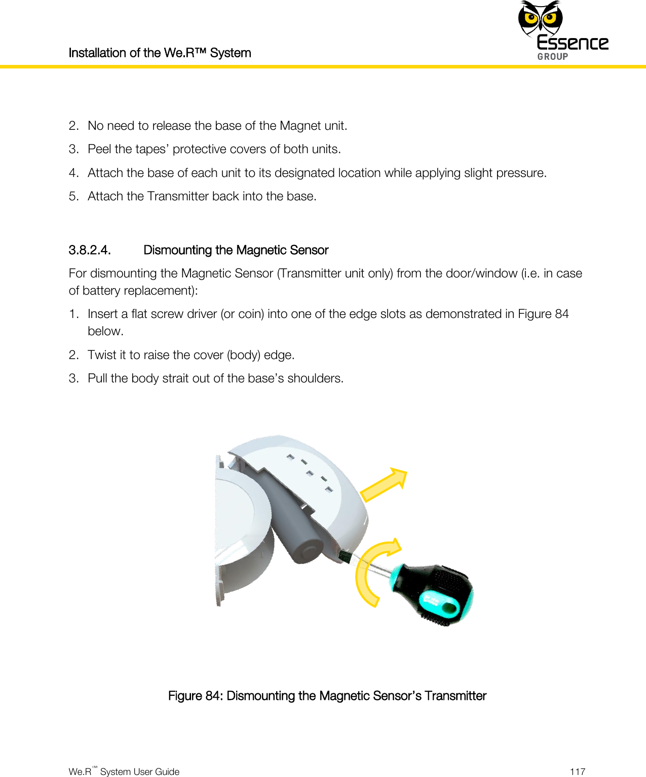
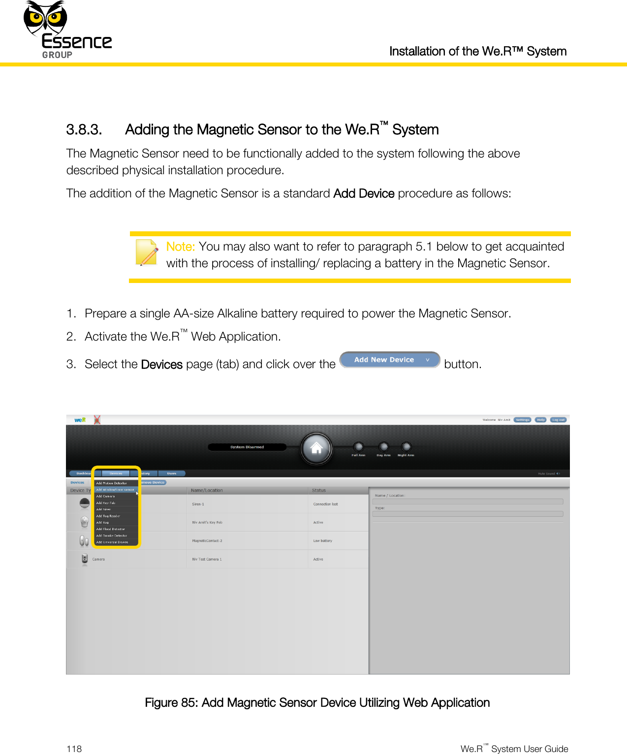
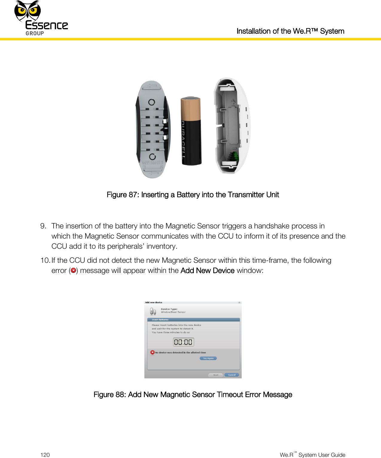
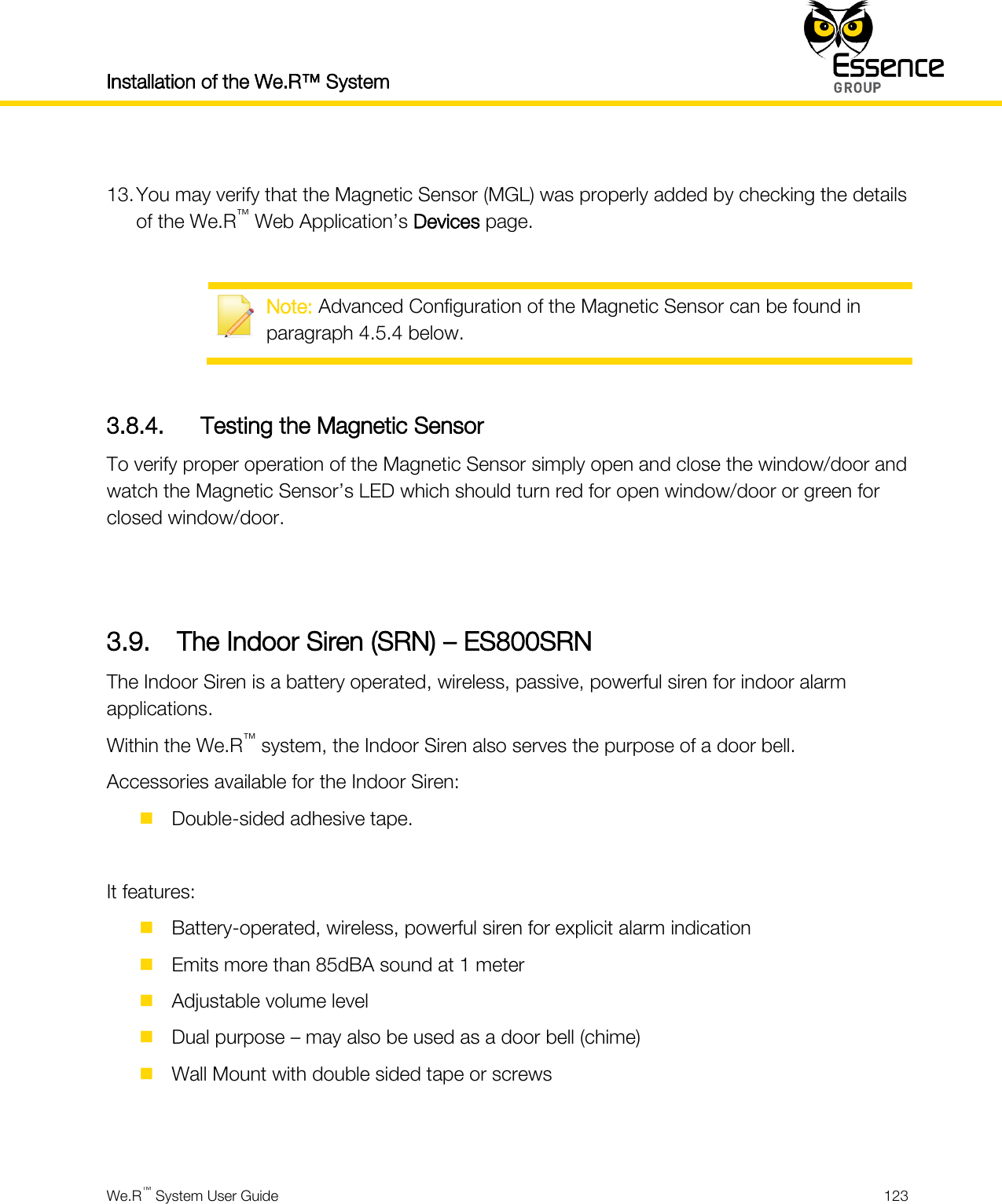
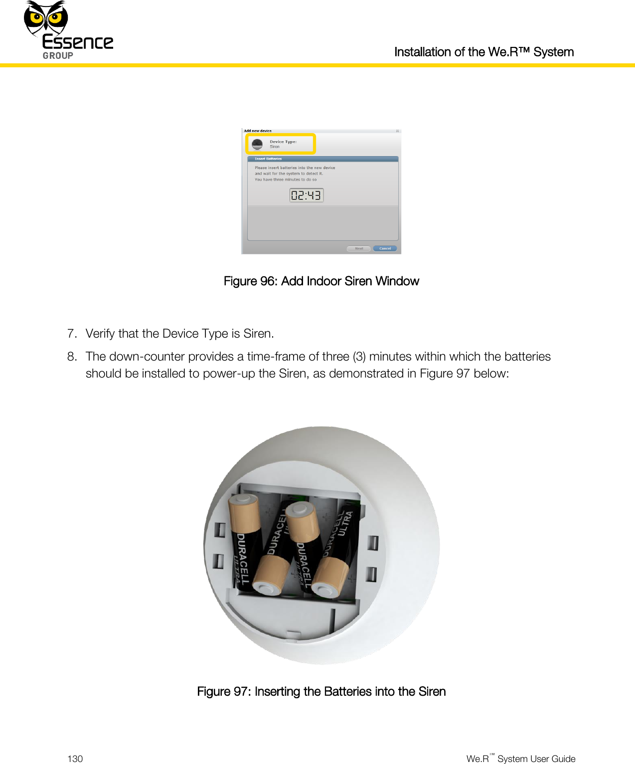
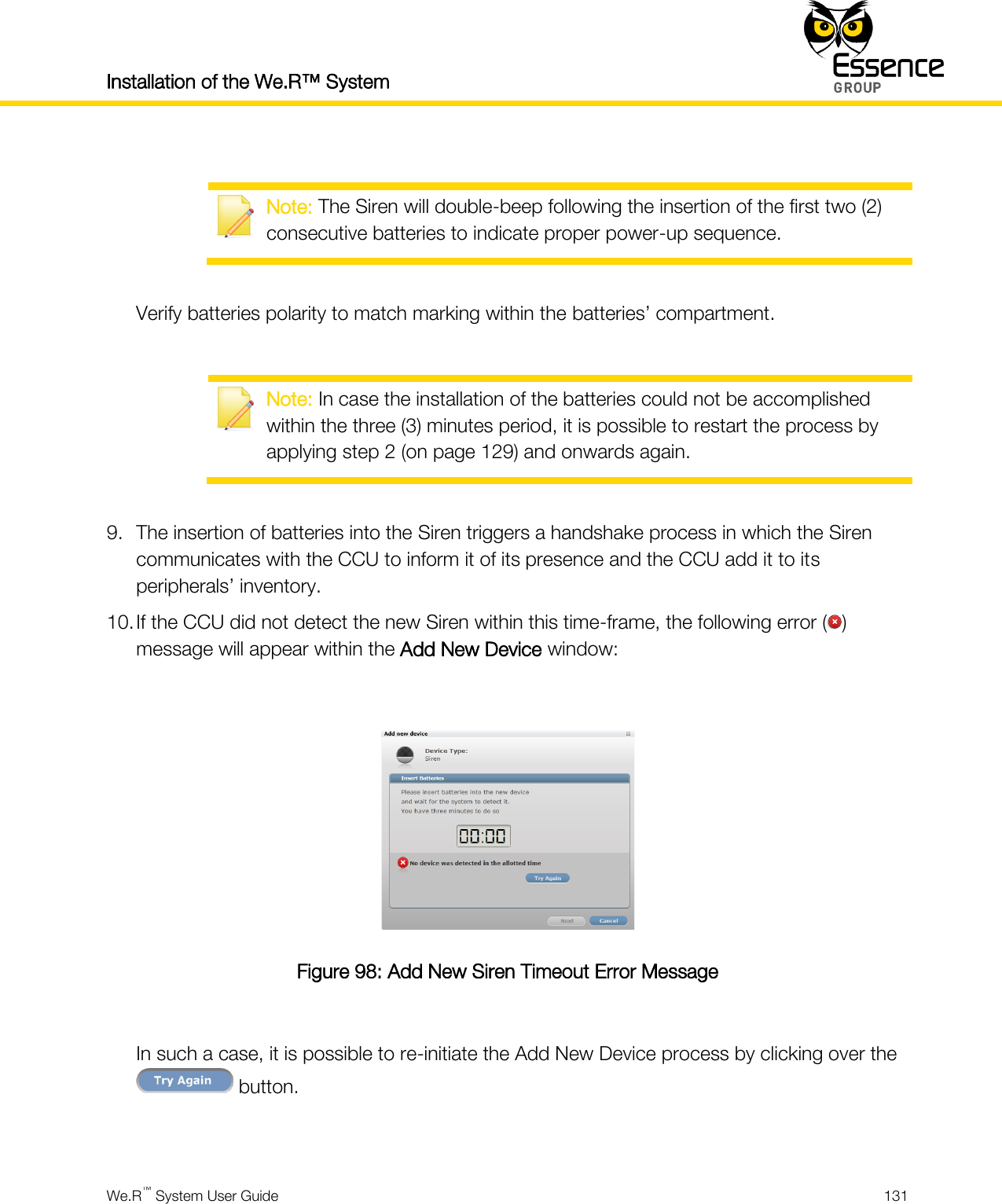
User manual _24734_part3


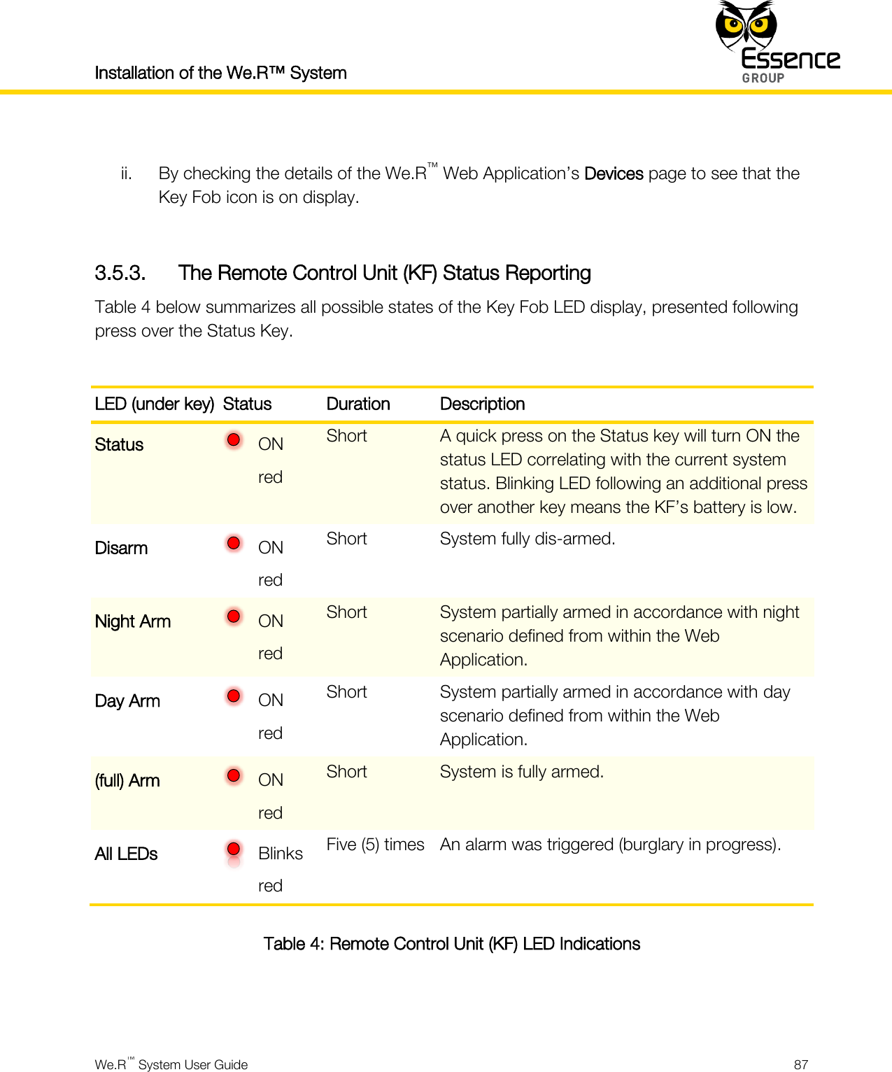


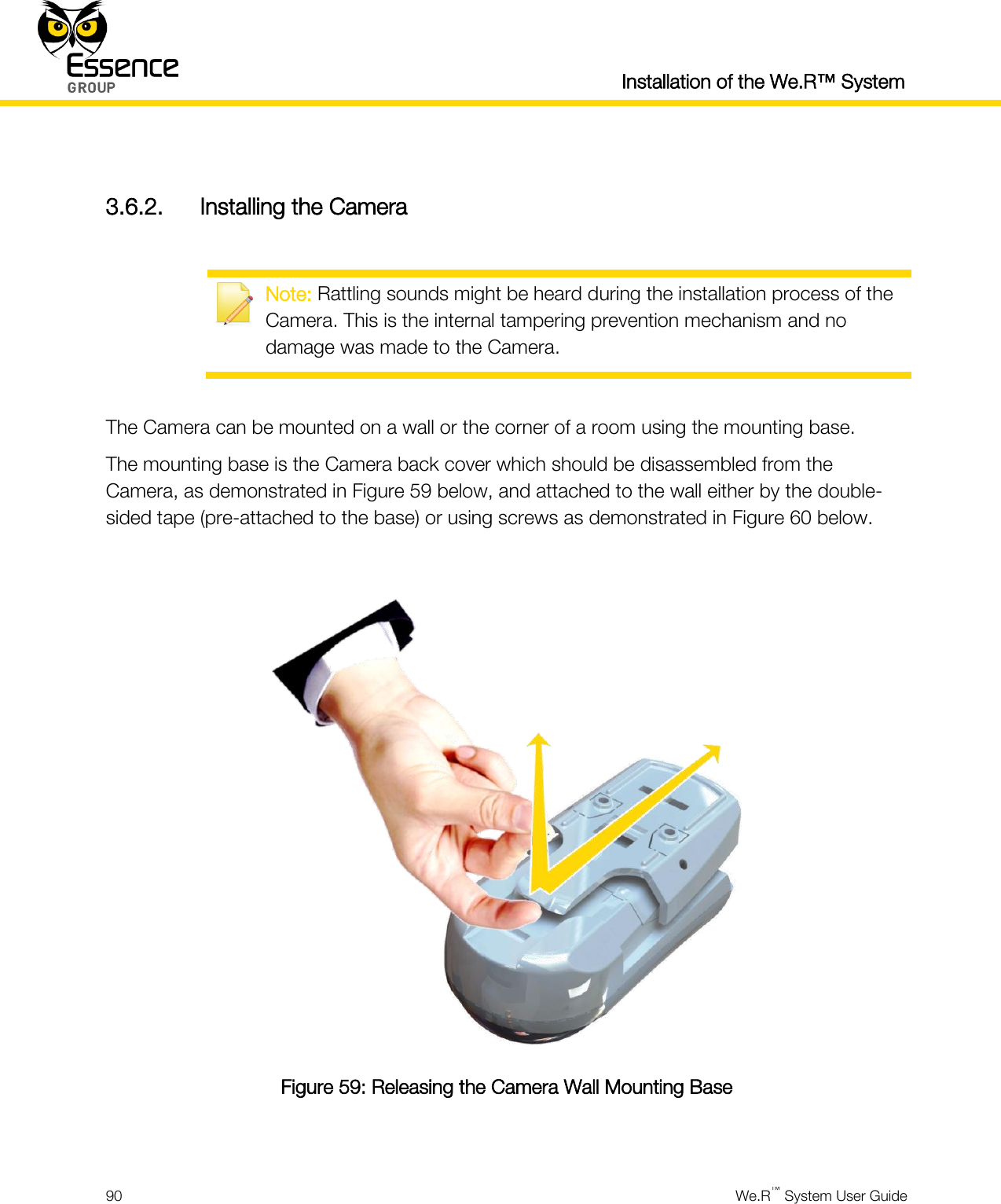


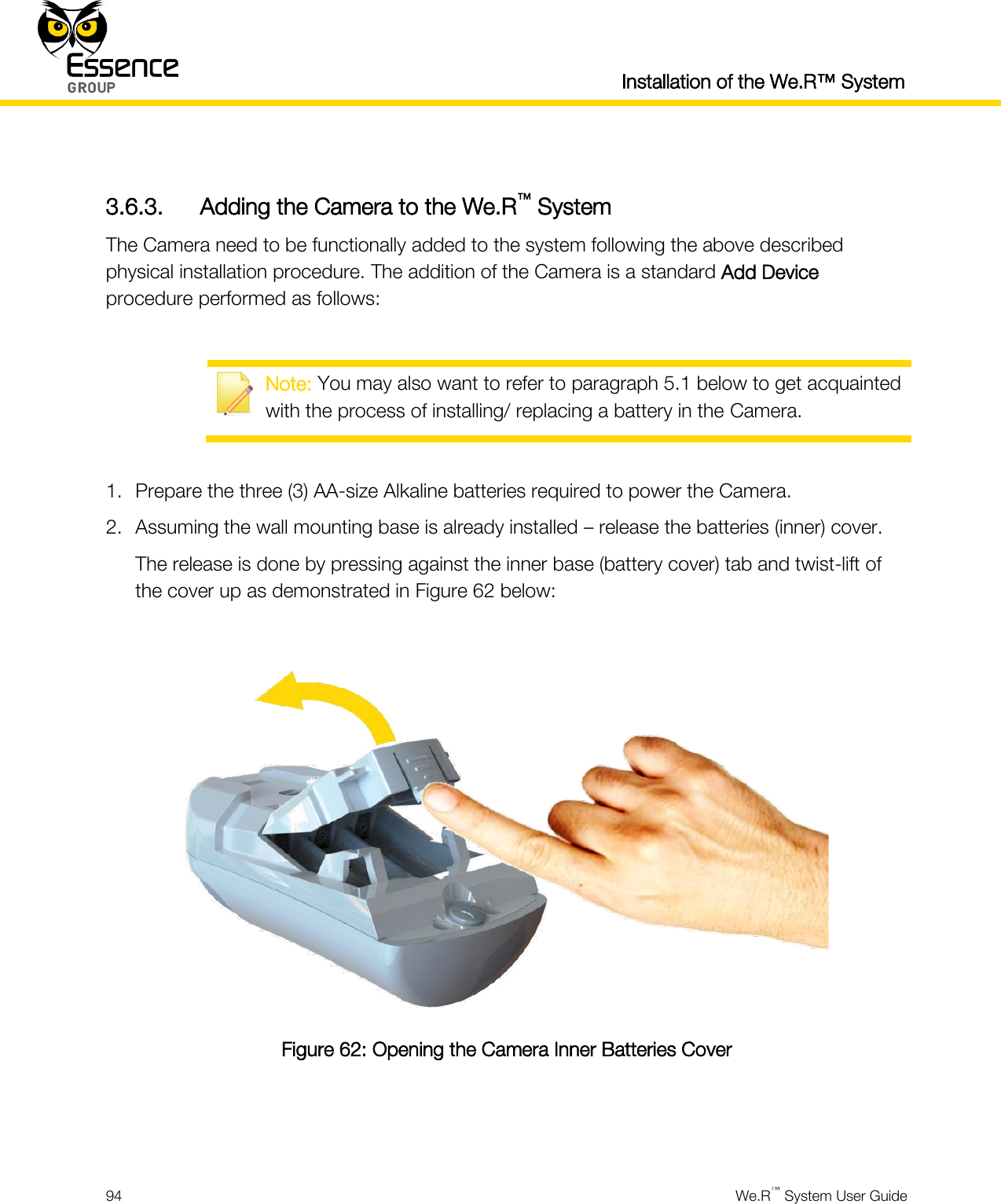

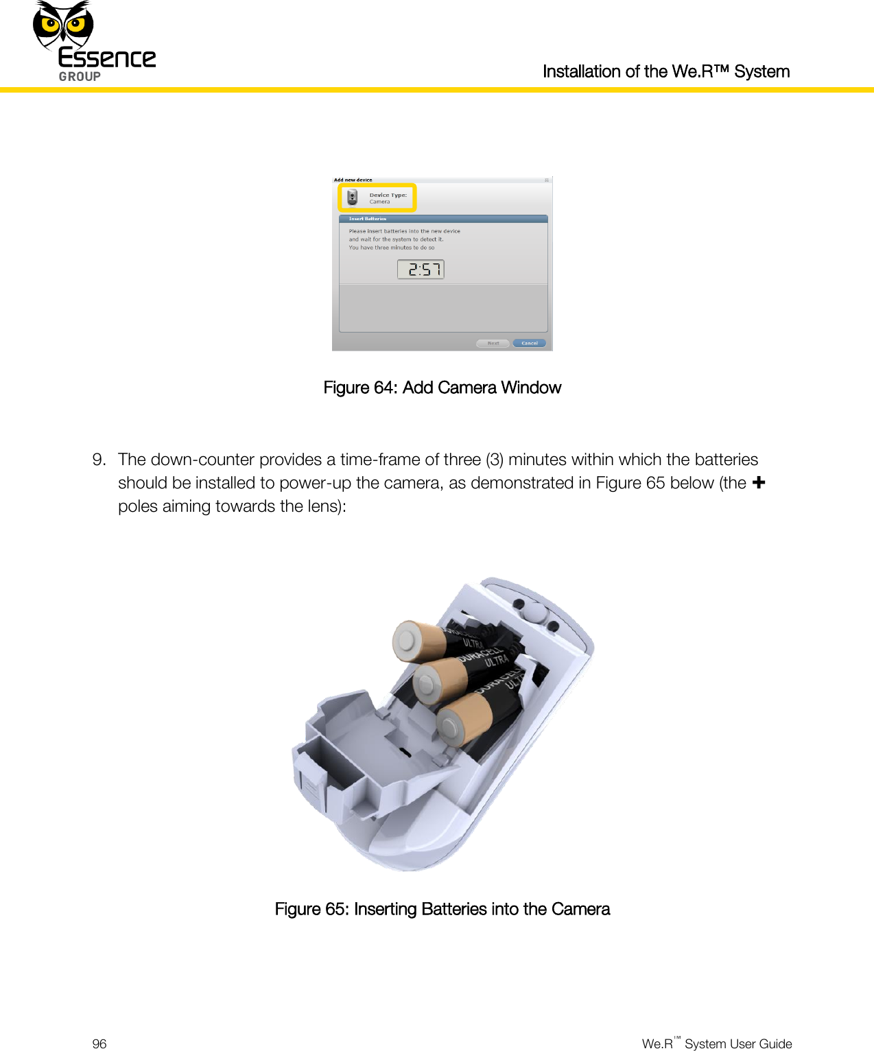


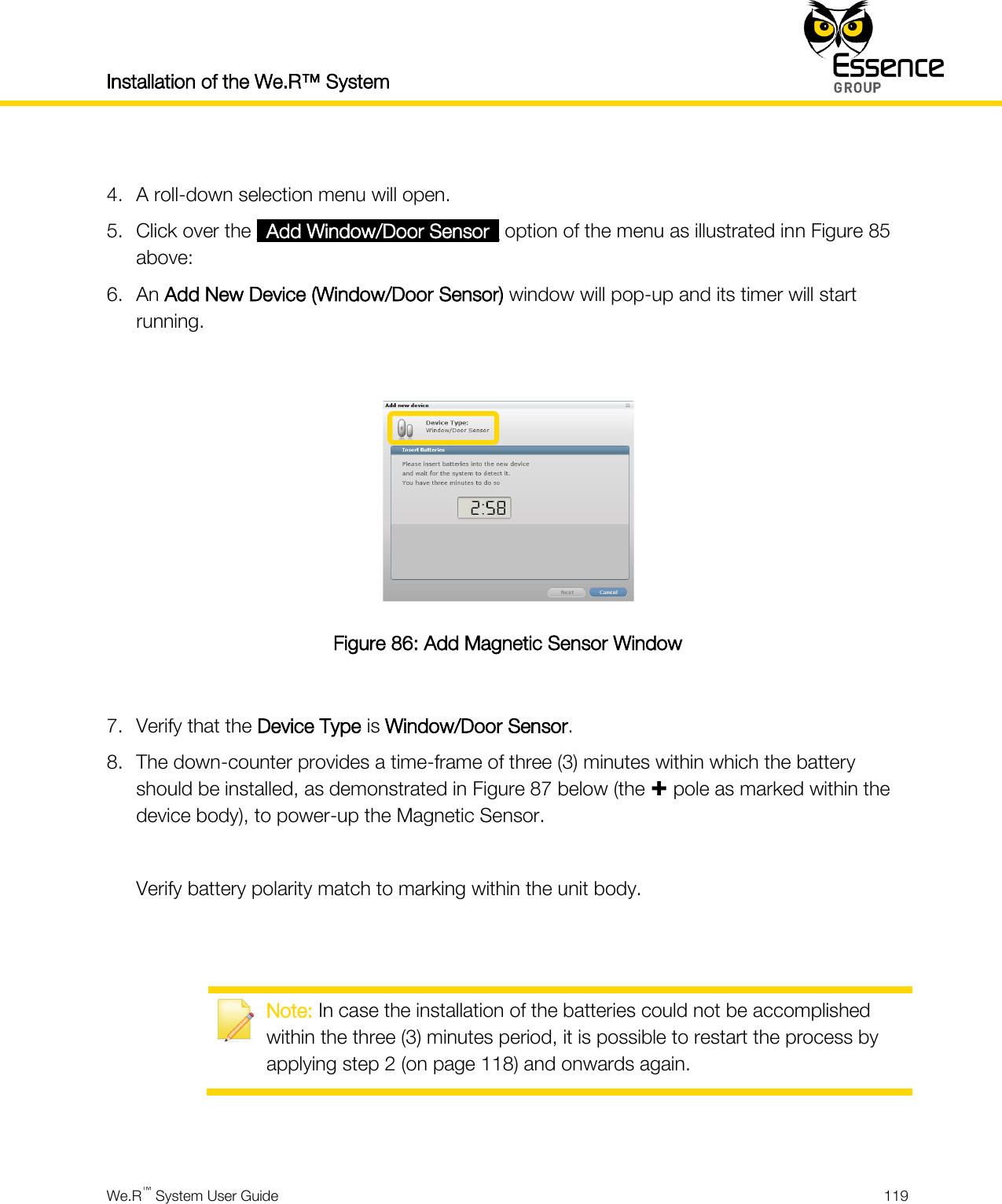

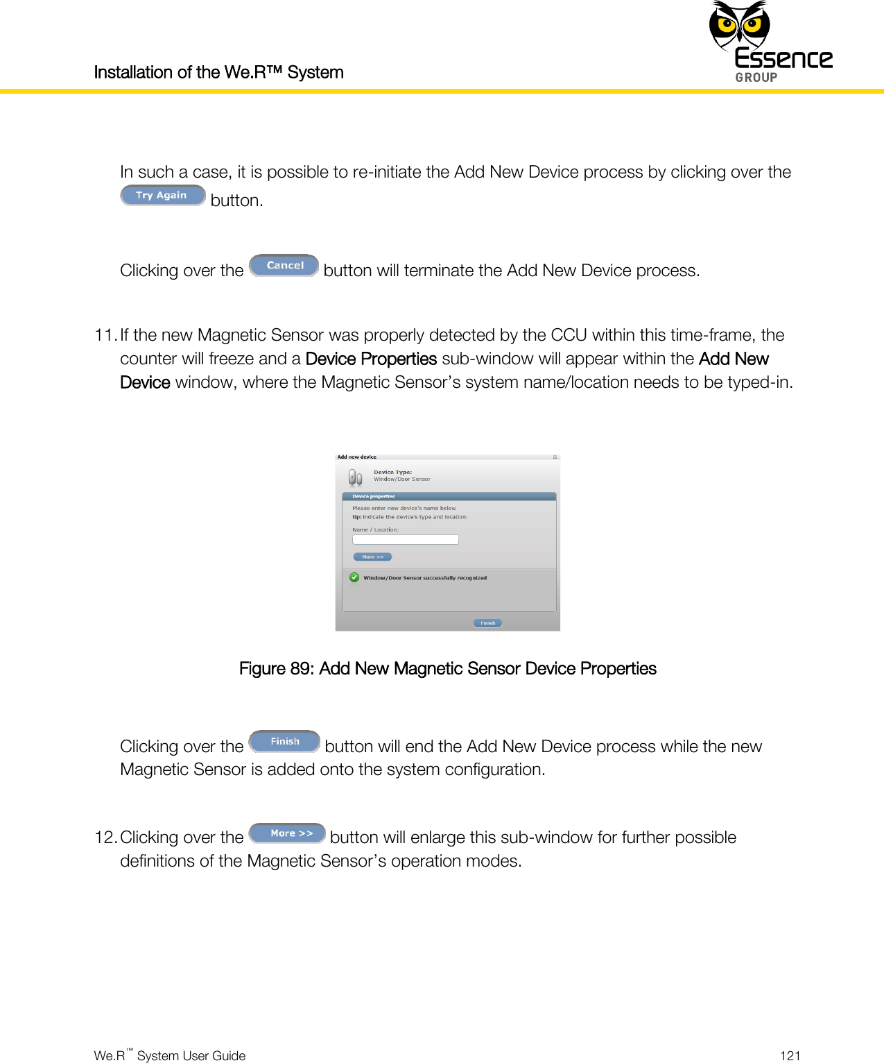
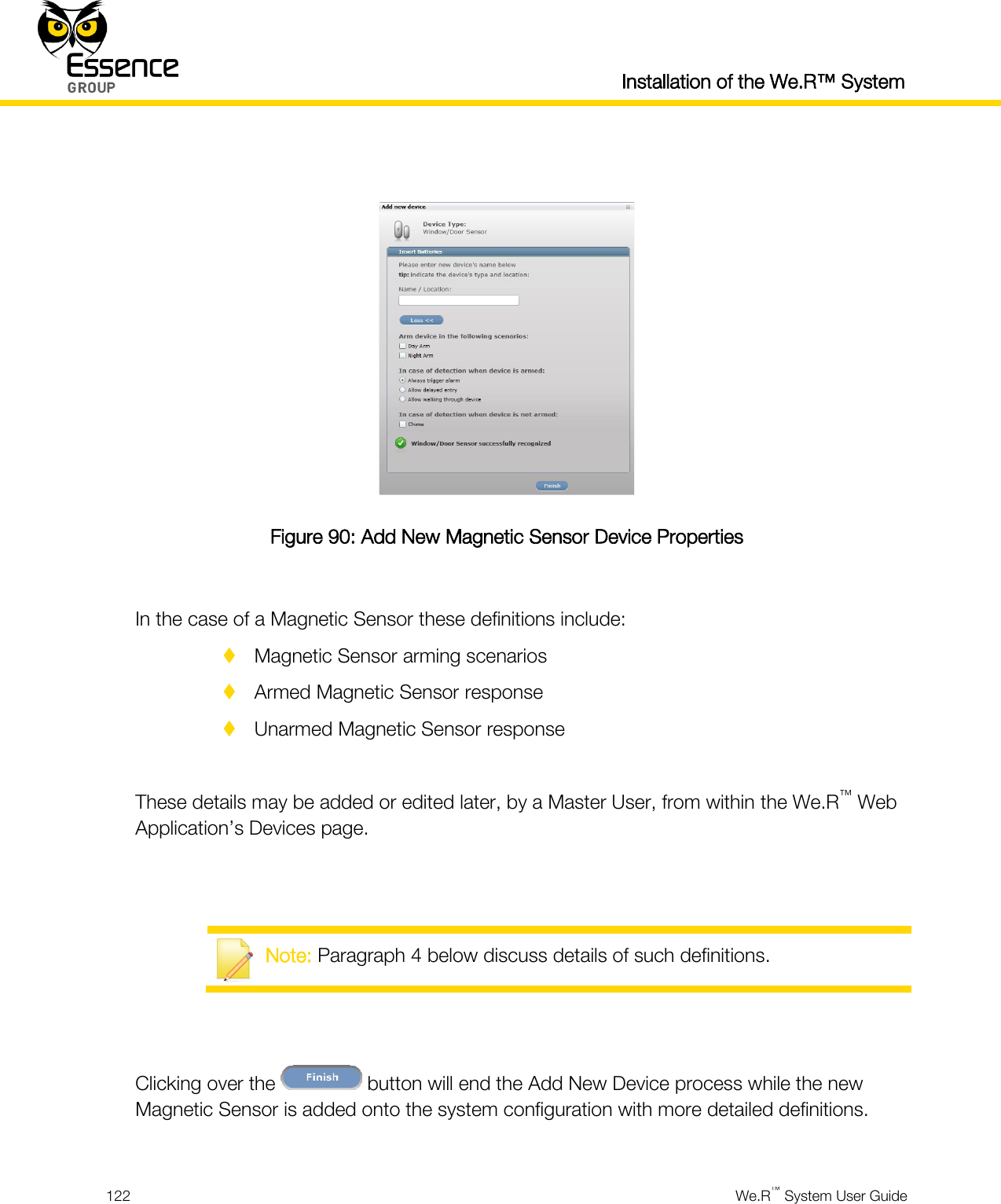


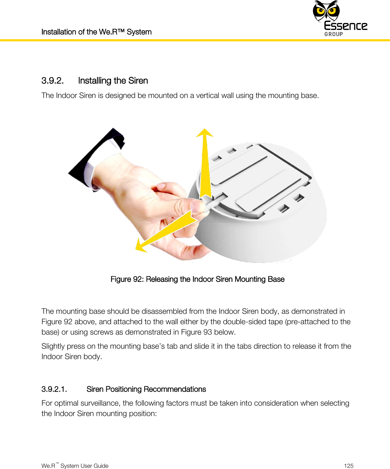
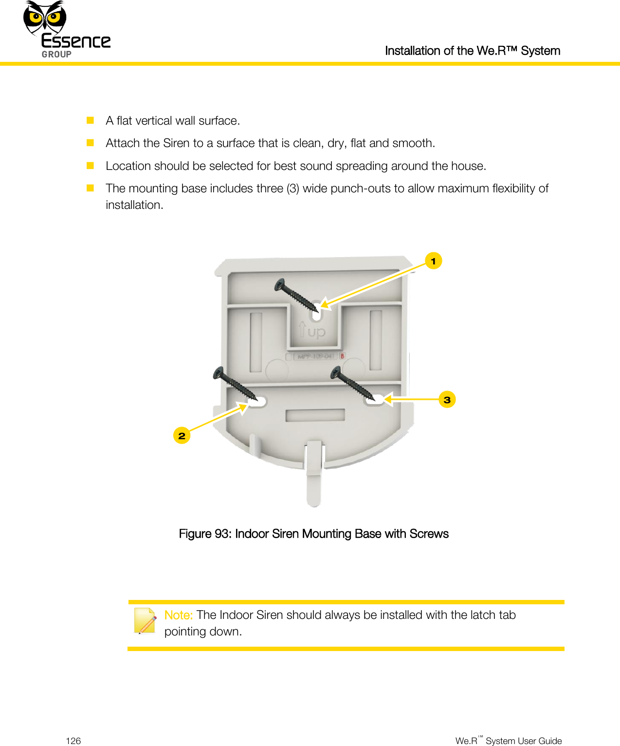


User manual_24734_part3