Ericsson Radio Access KRB1011047-1 Multicarrier cellular amplifier User Manual TUG
Ericsson Radio Access AB Multicarrier cellular amplifier TUG
UserManual.wiki
>
Ericsson Radio Access
>
KRB1011047-1 User Manual
>
Installation Manual
Contents
1.
user manuall cover page
2.
Installation Manual
Installation Manual
Navigation menu
Upload a User Manual
Namespaces
Wiki Guide
HTML
PDF
Info
Views
User Manual
Discussion / Help
Navigation
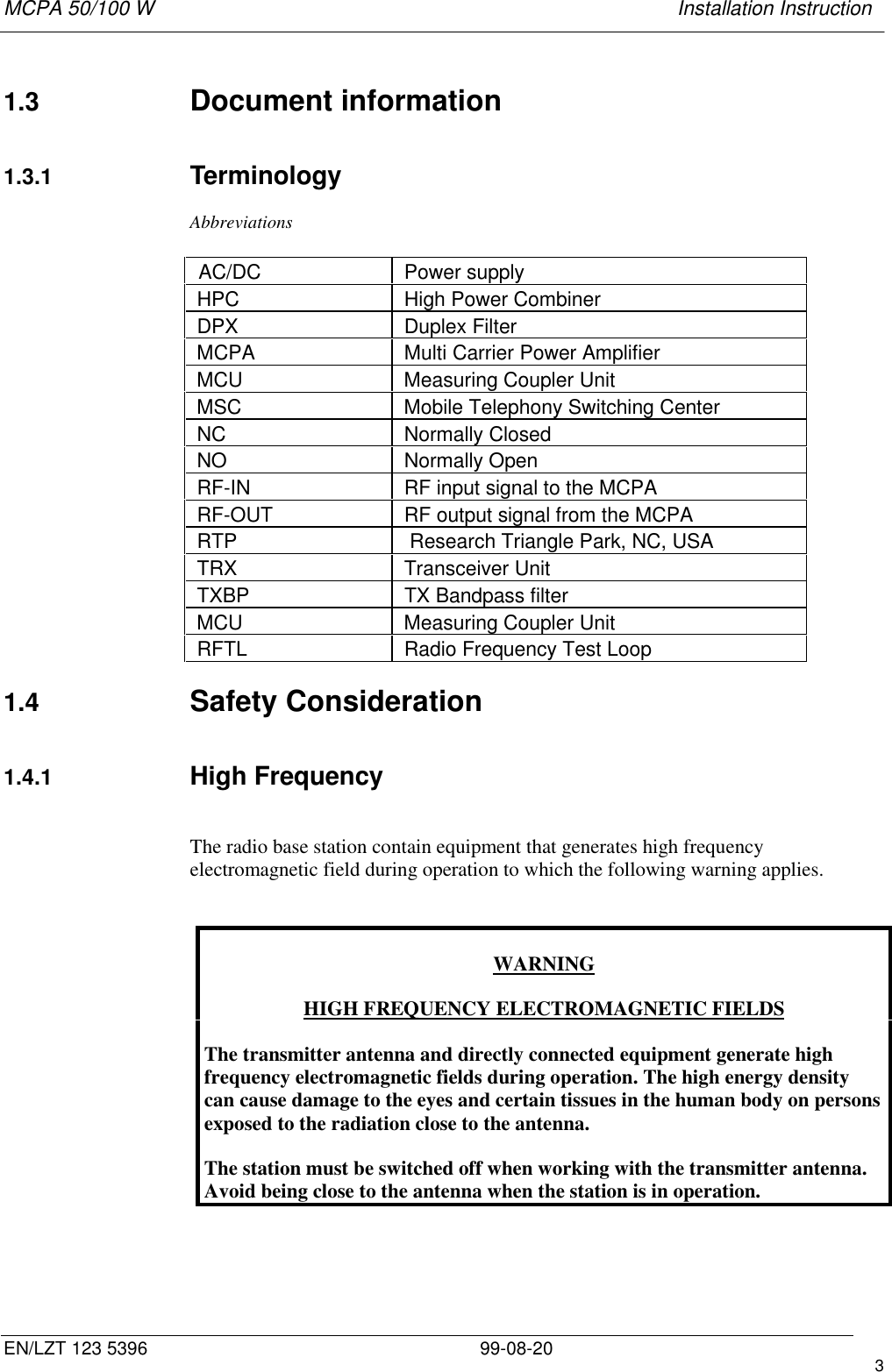
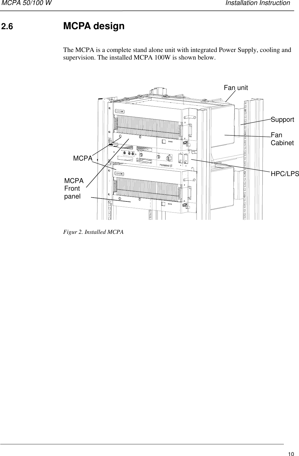
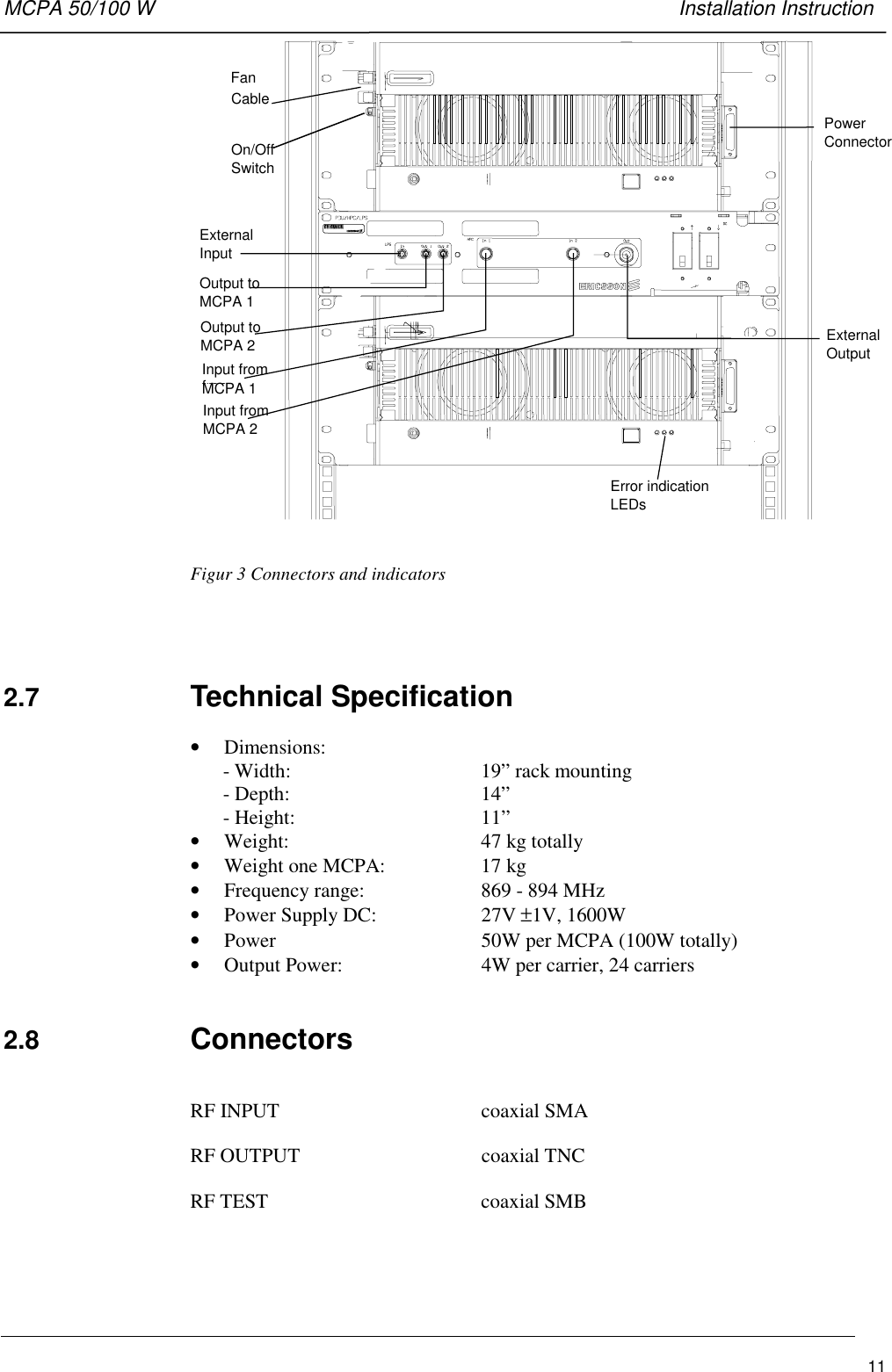
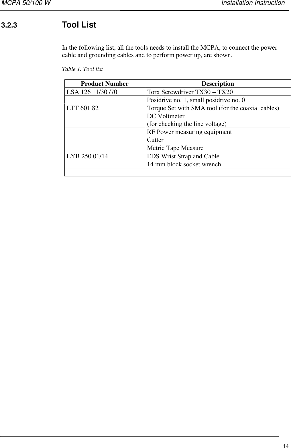
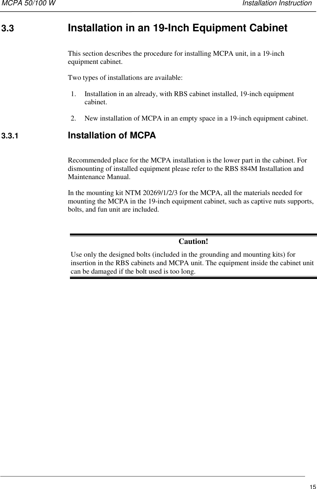
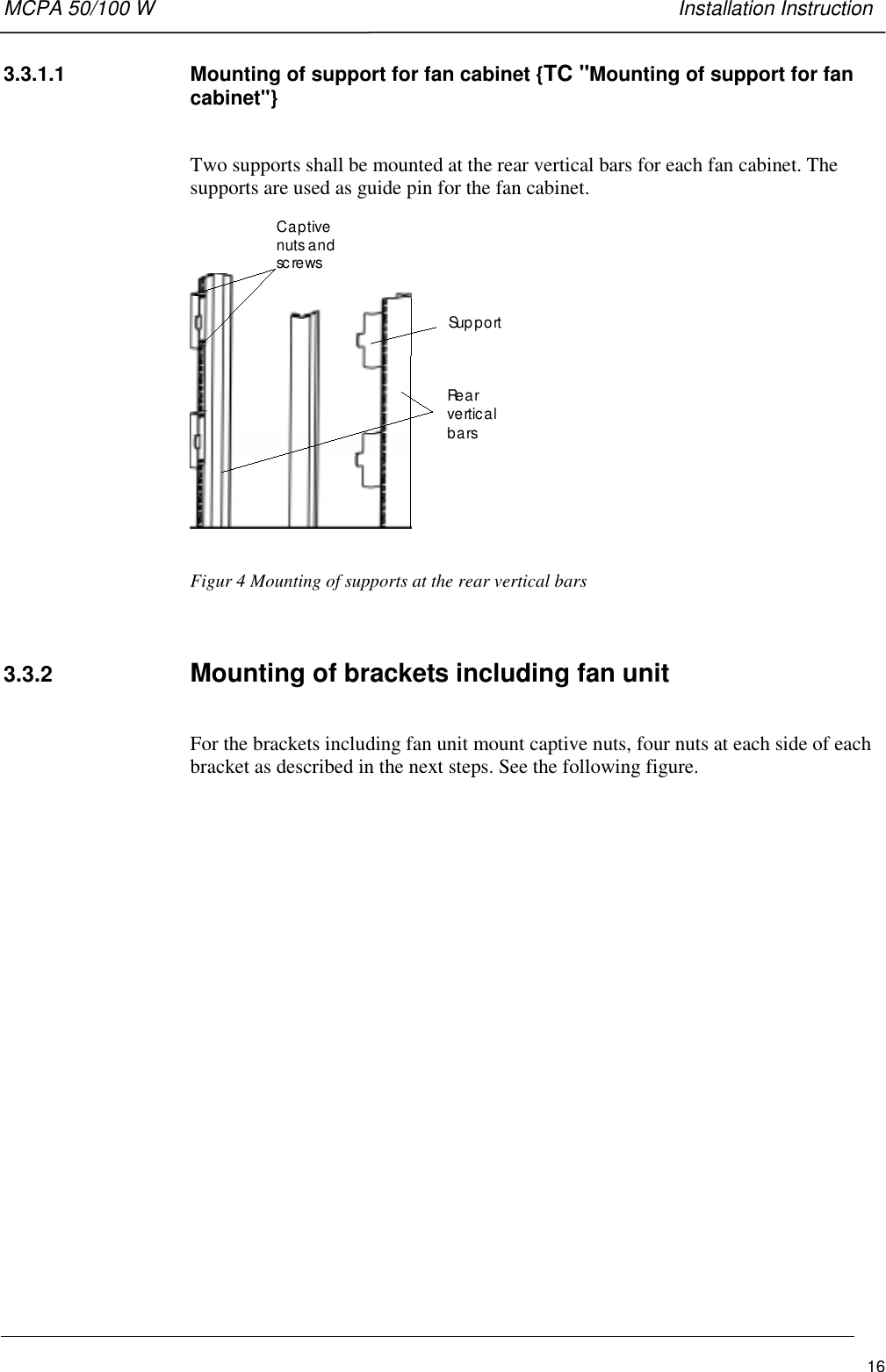
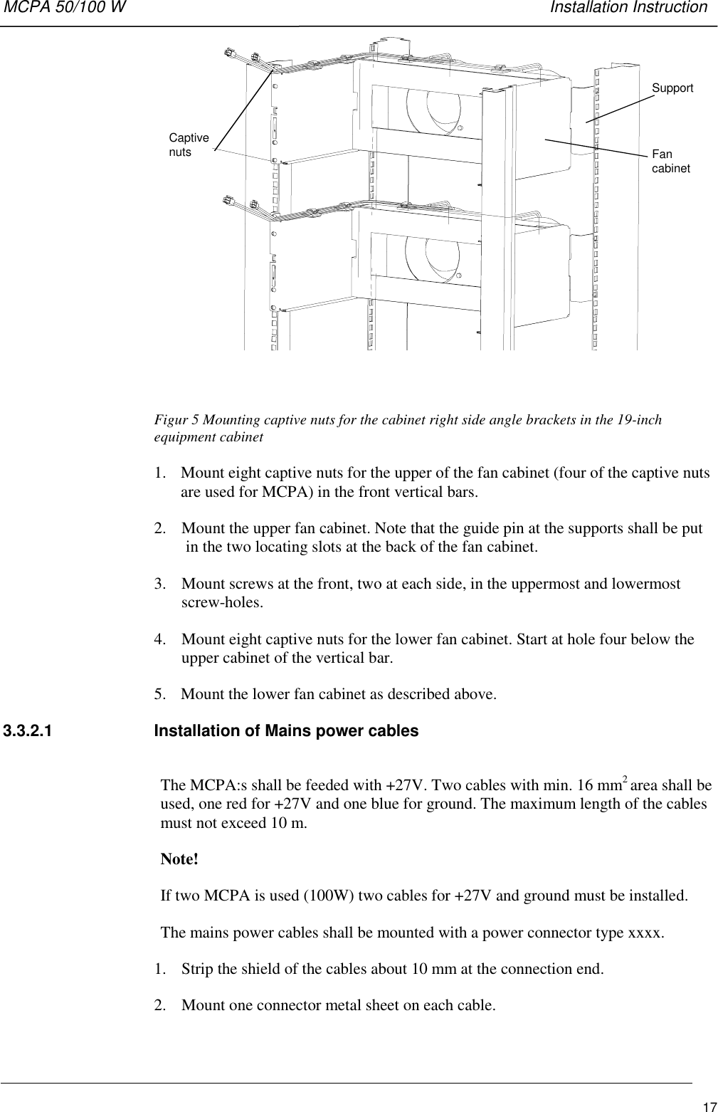
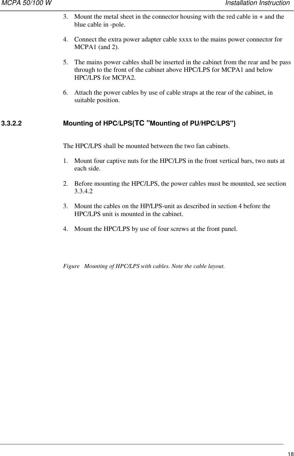
![MCPA 50/100 W Installation InstructionEN/LZT 123 5396 99-08-20 21 IntroductionThis part describes the information contained in the manual and the conventions usedin its presentation.1.1 Revision Information[J1]This is the first issue of the manual.1.2 About this manualThis manual contains the information required to install. troubleshoot, and maintainthe MCPA Multi Carrier Power Amplifier 50/100 W. The manual has references tothe RBS 884M Installation and Maintenance manual.It is assumed that before the manual is used to perform any of these activities at aRadio Base Station 884M (RBS 884M), the following actions have to be completed:• RBS884 installation (if not, read this manual anyhow)• DC power supply (27V) to MCPA must have been made availableThe manual is divided into the following parts:IntroductionA description of the contents of the manual and how the manual can be used.System DescriptionA description of the MCPA equipment hardware and the available configurations.InstallationProcedures for the installation, powering up and adjustment of MCPA equipment onsite.CablingProcedure for the cabling of the MCPA and HPC/LPS units.MaintenanceProcedures for basic troubleshooting and replacement of faulty items of equipment.The target audience for the manual is RBS 884M site installation and site main-tenance personnel.The procedures in the manual are normally intended to be performed in the orderpresented.](https://usermanual.wiki/Ericsson-Radio-Access/KRB1011047-1.Installation-Manual/User-Guide-77974-Page-2.png)
![Sidan: 2[J1]](https://usermanual.wiki/Ericsson-Radio-Access/KRB1011047-1.Installation-Manual/User-Guide-77974-Page-25.png)