Ericsson LG LWS-WK Wireless Telephone System User Manual Manual
Ericsson-LG Co., Ltd. Wireless Telephone System Manual
UserManual.wiki
>
Ericsson LG
>
LWS WK User Manual
Manual
Navigation menu
Upload a User Manual
Namespaces
Wiki Guide
HTML
PDF
Info
Views
User Manual
Discussion / Help
Navigation
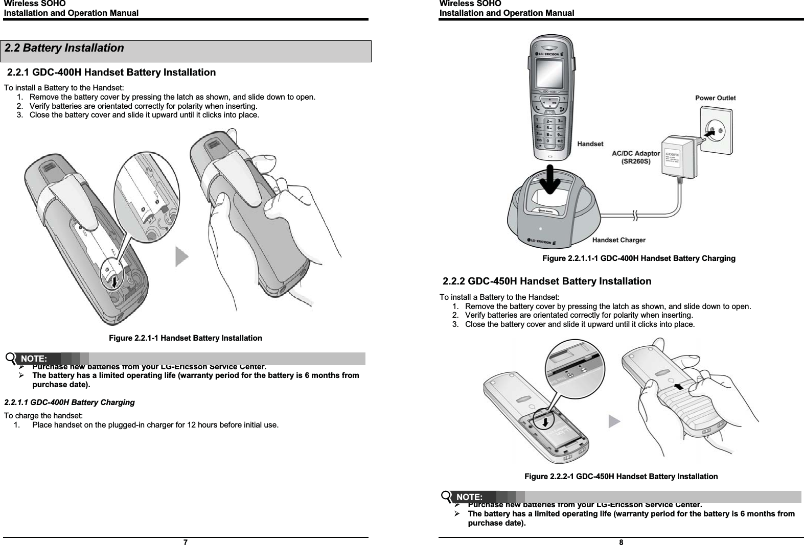
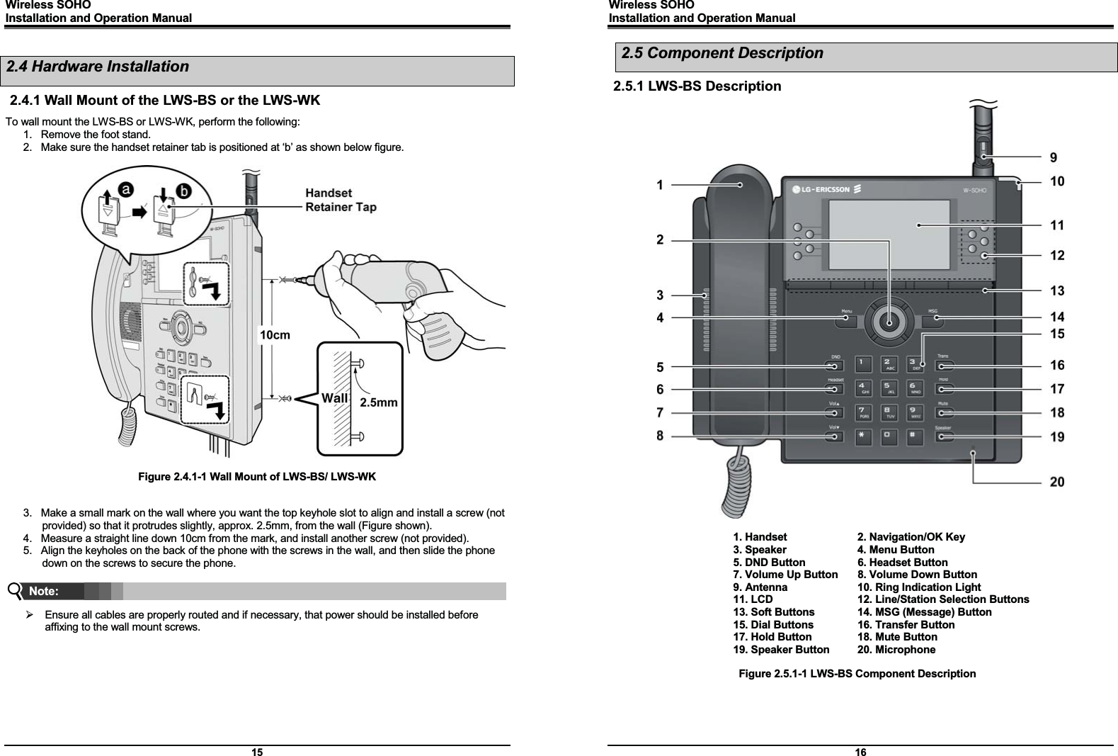
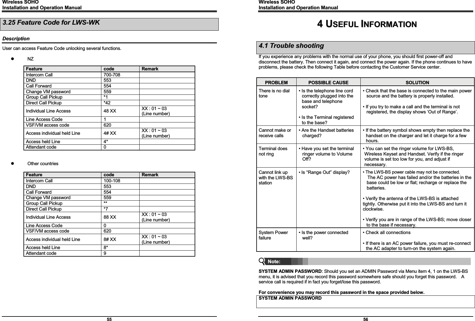
![Wireless SOHO Installation and Operation Manual 19 2.6 Hardware Initialization 2.6.1 LWS-BS and LWS-WK Once the LWS-BS and the LWS-WK have been properly installed in the desired locations, perform the following: 1. Plug in the AC/DC adapter to the LWS-BS or the LWS-WK (use only the included AC/DC adapter, SA-B122). 2. The LWS-BS or the LWS-WK is powered up and its display on the LCD will be activated. 2.6.2 Wireless Handset To start up the Handset: 1. Press and hold [ ] for approximately 2 seconds. 2. The handset automatically enters standby mode when a signal is located. 3. The handset automatically returns to standby mode whenever it is placed on the charger. To power-down the Handset: 1. Press and hold [ ] for approximately 3 seconds. 2.7 Display 2.7.1 LCD Specification User can select one of backlight control options (always on, always off, busy state on). 2.7.1.1 LWS-BS z 240 x 144 Graphic LCD z Backlit On/Off Control with 3 selectable option z Ten-Level Contrast Setting 2.7.1.2 LWS-WK z 240 x 42 Graphic LCD z Backlight On/Off Control z Ten-Level Contrast Setting Wireless SOHO Installation and Operation Manual 20 2.7.2 LCD Display 2.7.2.1 LWS-BS Figure 2.7.2.1-1 the LWS-BS LCD Display Screen 1. Antenna - Displayed when DCTU of LWS-BS works and it can be linked to DECT . 2. Call Forward – Icon indicates the base station is currently set for call forwarding. 3. Mute – Icon indicates if the mute button is activated for blocking voice transmission on your phone during a conversion. 4. Alarm – Icon indicates the alarm has been set. 5. Message – Icon indicates there is at least one new message. 6. Missed call – Icon indicates that there are missed calls in your absence. 7. USB – Icon indicates a USB memory device is inserted. 8. Station Number – Displayed in idle state. If the LWS-BS station has the designated name, the name is displayed. 9. Date & Time – Displayed in idle state. 10. Calendar – Displayed in idle state. 11. Soft Menu – Dependent on the status and menu choices, the current available selections are displayed. 2.7.2.2 LWS-WK 1. Antenna - Displayed when the LWS-WK is in the range of a LWS-BS where it can be linked. Disappears when it moves out of range. The closer it moves to the base, the stronger RSSI for reception is. 2. Message – Icon indicates there is at least one new message. 3. Date & Time –Displayed in idle state. 4. Keyset Number – Displayed in idle state. 5. Soft Menu – Dependent on the status and menu choices, the current available functions are displayed. 1 2 345678 9 10 11](https://usermanual.wiki/Ericsson-LG/LWS-WK/User-Guide-1428959-Page-13.png)
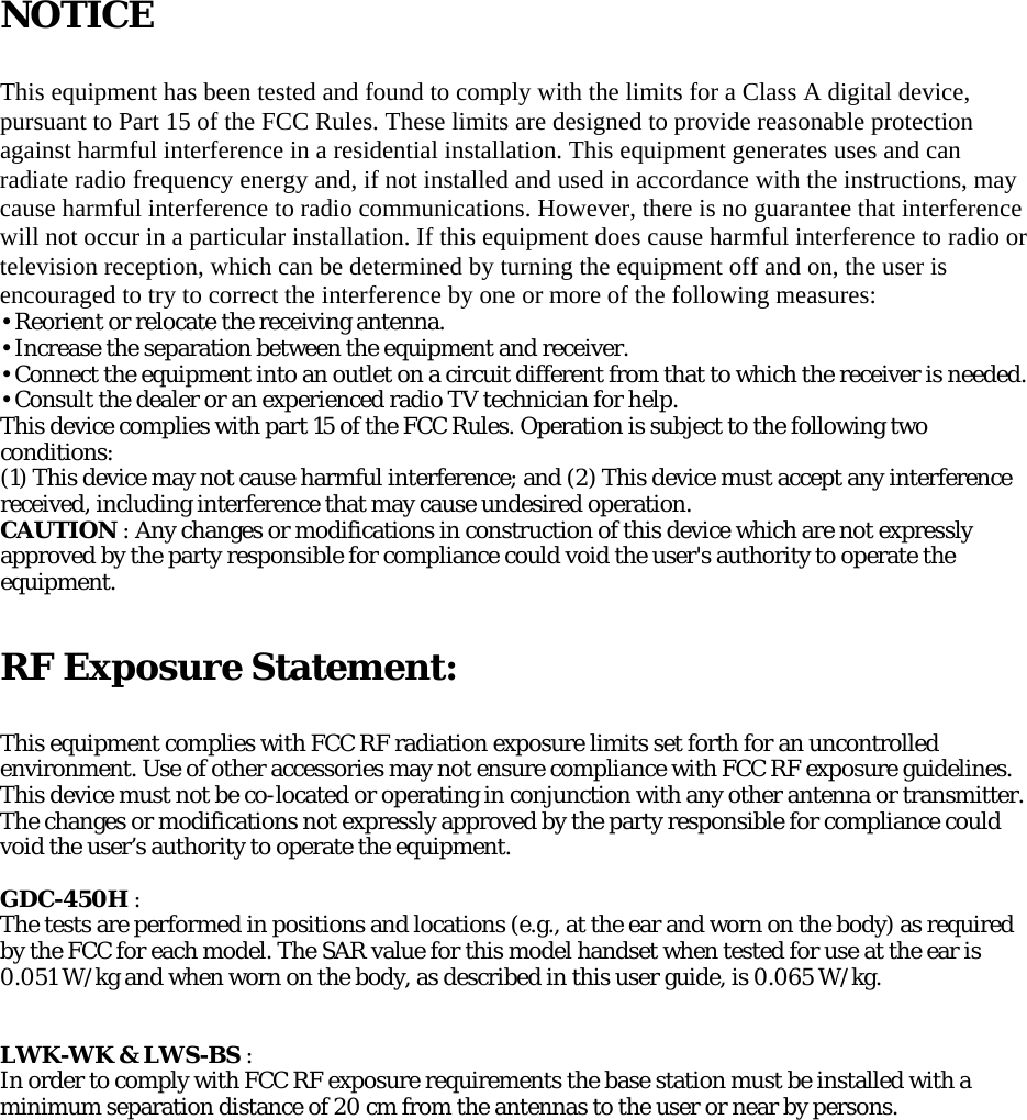
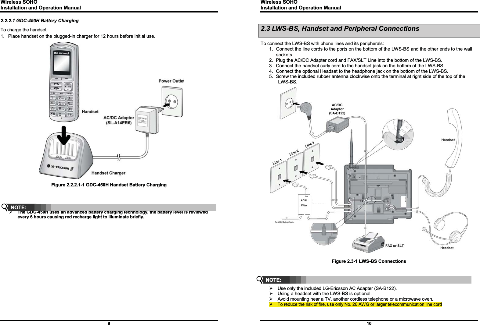
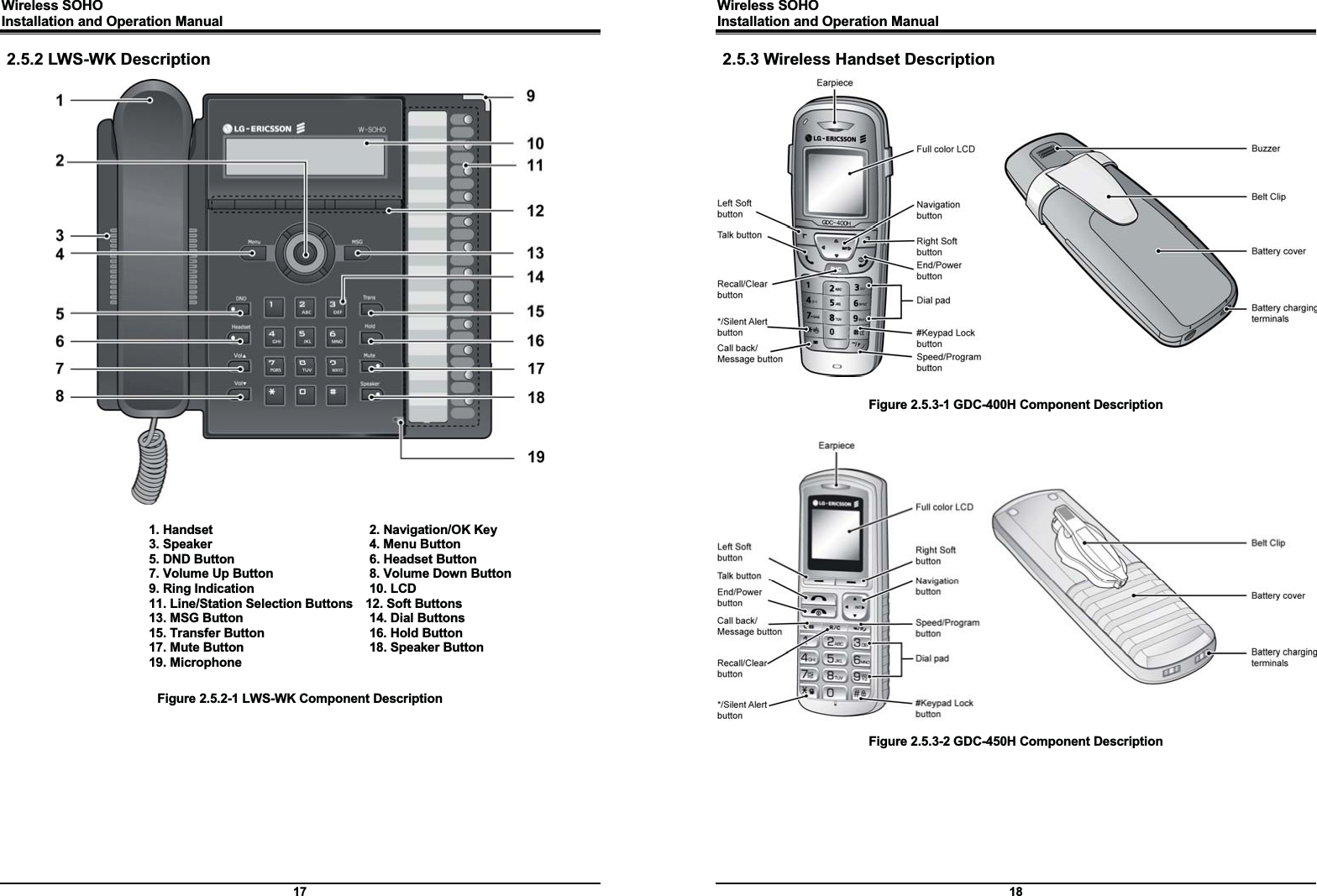
![Wireless SOHO Installation and Operation Manual 21 2.7.2.3 GDC-400H and GDC-450H Wireless Handset 1. Antenna - Displayed when the handset is in the range of a LWS-BS where it can be linked. Disappears when it moves out of range. The closer it moves to the base, the stronger RSSI for reception is. 2. Message – Icon indicates there is at least one new message. 3. Date & Time – Displayed in idle state. 4. Battery – Displays battery level when a handset keeps operating. 5. Handy Number – Displayed in idle state. 6. Soft Menu – Dependent on the status and menu choices, the current available functions are displayed. Wireless SOHO Installation and Operation Manual 22 2.8 Keypad Description 2.8.1 LWS-BS FUNCTIONAL CLASSIFICATION BUTTON NAME BUTTON DESCRIPTION Flex Keys Line selection button Line 1 ~ 3 Access an idle Line for making external call or answer the incoming call by pressing the line button. Station button Station 101~107 Allows you to make an intercom call. Station 101~107 : Wireless Terminals Soft Menu Keys Soft key 1,2,3 Dependent on the status and menu choices, the current available functions are displayed. Menu Main Menu MSG Retrieve Messages Navigation button Up/down/right/left/ok Function Keys DND Set Night/Weekend mode Headset Headset mode or speakerphone mode is switched by pressing the [Headset] button in idle state. Headset LED will be illuminated when headset mode is selected. Vol. up To turn Handset or Speaker volume up during a call/off hook. Ringer volume is turned up if phone is ringing. LCD contrast is turned up if phone is in idle state. Vol. down To turn Handset or Speaker volume down during a call/off hook. Ringer volume is turned down if phone is ringing. LCD contrast is turned down if phone is in idle state. Trans An intercom call or line call can be transferred to another station or line during a conversation. Hold When on a call, the station user can place an active call on hold; the held party will hear a hold tone. Mute During a conversation, pressing the [MUTE] button will disable the handset microphone or the speakerphone whilst continuing to listen to the other party. Pressing the [MUTE] button again, will reactivate the microphone. This button is active on all calls. Speaker Pushing the [Speaker] button allows the user to make or continue a call using the Speaker for two-way communication. Pressing the [Speaker] button again, will terminate the call. EXIT on Menu Dial Pad 0~9, *, # Use to dial a number, select a menu item, or input values. 2.8.2 LWS-WK FUNCTIONAL CLASSIFICATION BUTTON NAME BUTTON DESCRIPTION Flex Keys Line selection button Line 1 ~ 3 Access an idle Line for making an external call or answer the incoming call by pressing Line button. Station button Station 100~108 Allows you to make an intercom call. Station 100 : Base Station Station 101~107 : Wireless Terminals Station 108 : SLT/FAX Soft Menu Keys Soft key 1,2,3 Dependent on the status and menu choices, the current available functions are displayed.](https://usermanual.wiki/Ericsson-LG/LWS-WK/User-Guide-1428959-Page-14.png)
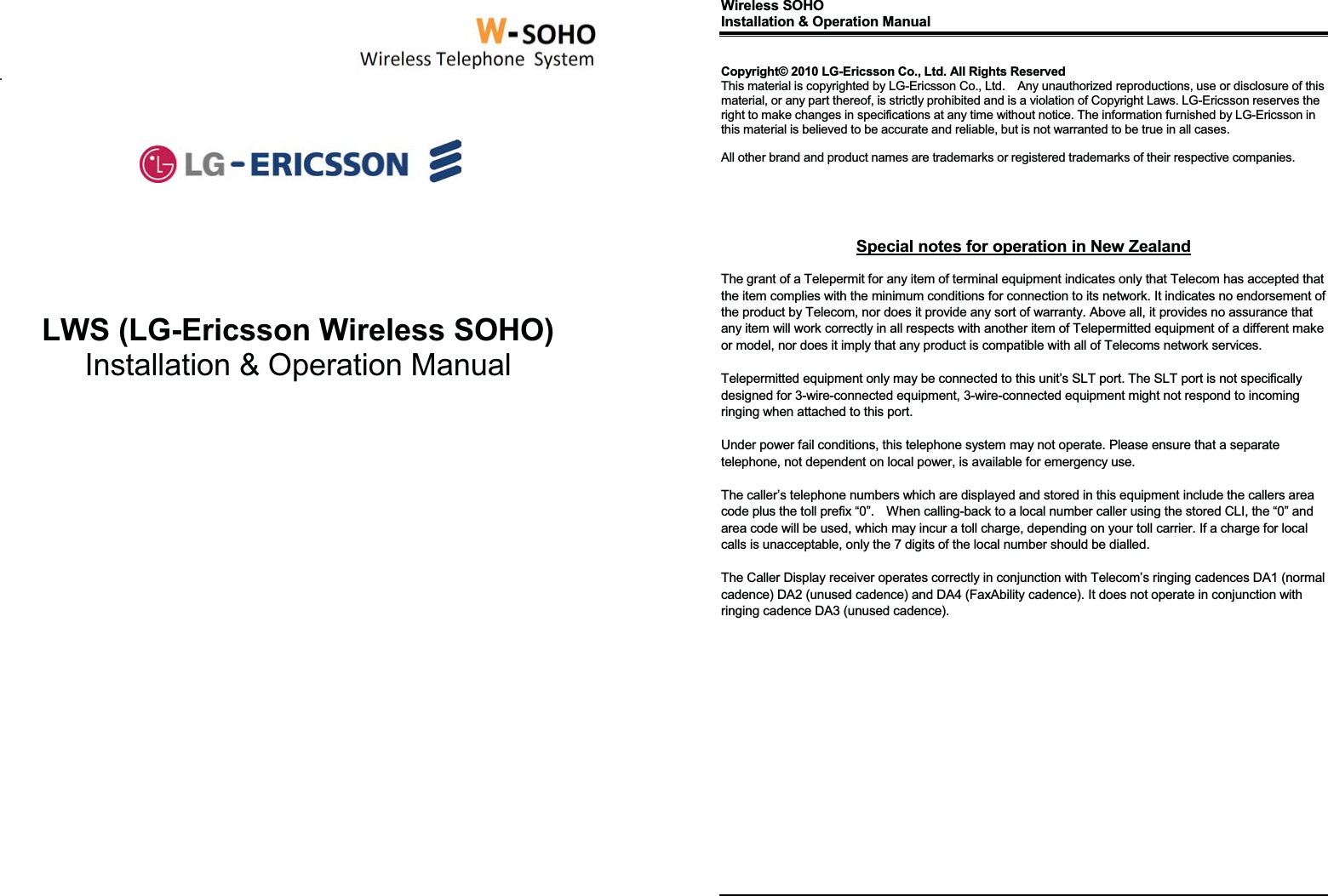
![Wireless SOHO Installation and Operation Manual 23 FUNCTIONAL CLASSIFICATION BUTTON NAME BUTTON DESCRIPTION Menu Main Menu MSG Retrieve Messages Navigation button Up/down/right/left/ok Function Keys DND Blocks incoming calls ringing. This applies to outside calls, intercom calls and transfers Headset Connecting an optional headset to the station allows hands-free conversations by pressing [Headset] button. An industry standard headset can be connected to a stationVol. up To turn Handset or Speaker volume up during a call/off hook. Ringer volume is turned up if phone is ringing. LCD contrast is turned up if phone is in idle state. Vol. down To turn Handset or Speaker volume down during a call/off hook. Ringer volume is turned down if phone is ringing. LCD contrast is turned down if phone is in idle state. Trans An intercom call or a line call can be transferred to another station or line during a conversation. Hold When on a call, the station user can place an active call on hold; the held party will hear a hold tone. Mute During a conversation, pressing the [MUTE] button will disable the handset microphone or the speakerphone whilst continuing to listen to the other party. Pressing the [MUTE] button again, will reactivate the microphone. This button is active on all calls. Speaker Pushing the [Speaker] button allows the User to make or continue a call using the Speaker for two-way communication. Pressing the [Speaker] button again, will deactivate the Speaker, and send call transmission to the handset (if in use) or terminate the call. Dial Pad 0~9, *, # Use to dial a number, select a menu item, or input values. 2.8.3 GDC-400H/450H Wireless Handset Button Function [TALK] To make a call Î Redial number saved in handset. [END/POWER] END/POWER] To end a call Press for less than 1 second : Power Off Press for less than 1 second :Leave a call back or a message Press for less than 1 second: Ignore an incoming call. [LEFT SOFT / RIGHT SOFT] Access to the current functions by pressing the soft button directly below this symbol. Wireless SOHO Installation and Operation Manual 24 Button Function [RECALL/CLEAR] Talk Mode : Register recall Recall a call and retry next call When using pre-dial : Î Press for longer than 1 second : All digits are cleared Î Press for less than 1 second : 1 digit backspace Î When using local functional operation : Function cancel (It should be pressed for longer than 1 second) [SPEED/PROGRAM] Post-Dial : Î Press for less than 1 second: System speed dial(SPEED). Î Press for longer than 1 second: Start/Finish a system program (PROGRAM). [LEFT] In an idle state : To view missed call In MENU : LEFT [RIGHT/INTERNAL/TRANSFER/HOLD] Talking Mode : Î Press for less than than 1 second: Transfer a call to another station(TRANS). Î Press for longer than 1 second: Hold a call / release a holding call(HOLD). In an idle state : Î In MENU : right button Î To make a intercom call or a line call [CALL BACK] Press less than 1 second : Leave a call back or a message G [UP/DOWN] Talk Mode : Up / Down the level of Rx volume, Call by name, CLIP Standby Mode : Î In Menu: Navigate and select among function items in a menu or submenu. No inputted state : Î UP : Local Redial Î DOWN : Phonebook list To lock Keypad (Press for longer than 1 second) ‘#’ Display (Press less than 1 second) While Dialing: To insert pause (Press for longer than 1 second) G Talk Mode : Camp-On Standby Mode : Î ‘*’ is displayed (Press for shorter than 1 second) Î Enable/disable manner mode(Press for less than 1 second) 0~9 - Standard dial button](https://usermanual.wiki/Ericsson-LG/LWS-WK/User-Guide-1428959-Page-15.png)
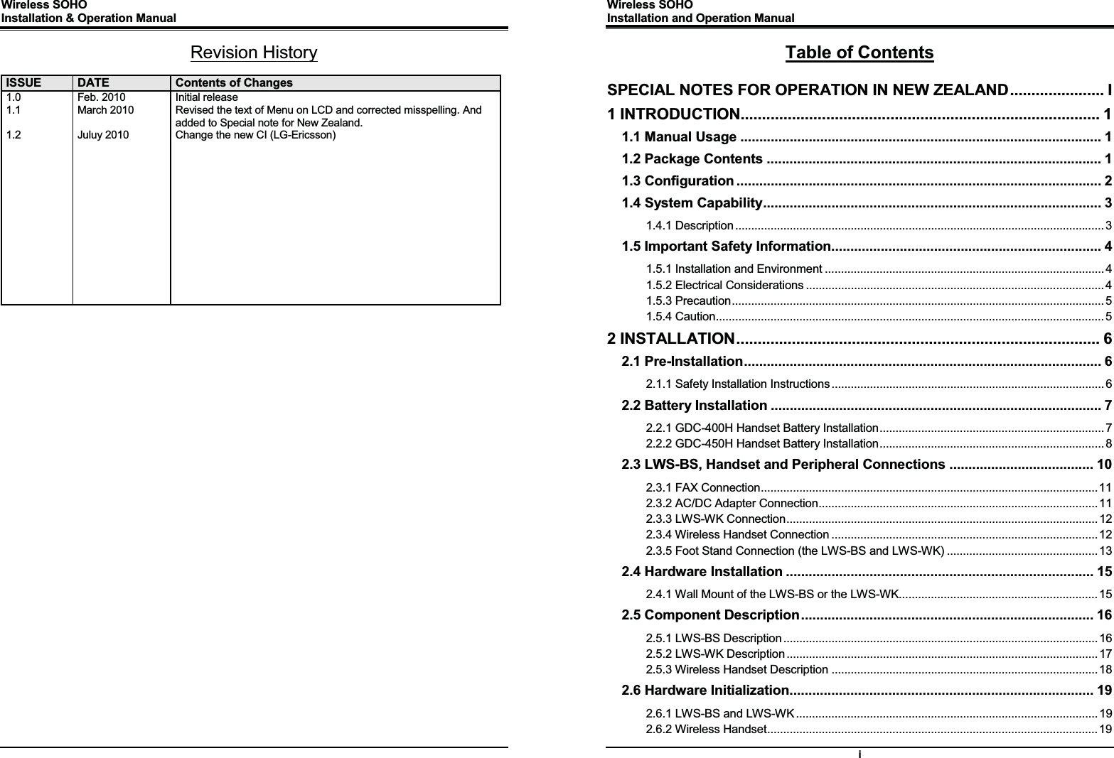
![Wireless SOHO Installation and Operation Manual 25 2.9 LED Operation Description 2.9.1 LWS-BS and Wireless Keyset FUNCTIONAL CLASSIFICATION LED OPERATION LED DESCRIPTION Ring Indicator RED Blink Indicates incoming ring signal Line Selection Button Green/RED Blink Line is in hold state Green blink: Line is held by the own station Red blink: Line is held by others Orange Blink Indicates ringing state Green steady on The green LED illuminates when you are on a call Red steady on The red LED indicates that the associated line is in use by other user Station Selection Button ON (RED) Illuminates when you or others are on a call Red Blink Ringing state indication OFF Idle State DND, Headset Mute, Speaker ON Illuminates when each function is activated. OFF Function is deactivated Blinking rate: z Base Station : 0.5/sec. z Wireless Keyset : 0.78/sec. Note: Wireless SOHO Installation and Operation Manual 26 2.10 Configuration 2.10.1 Country code To set the nation code, perform the following: 1. Press the [Menu] button on the LWS-BS. 2. Select 1. CONFIGURATION > 2. COUNTRY. 3. If you want to change country, press [CHANGE] soft key or [OK] Navigation key. 4. Set the Country code (refer to the blow Nation Code Table). 5. When finished, press the [SAVE] button, and system will ask you to confirm it. 6. If you select [YES] as pressing digit 1, system will restart and database will be initialized. Nation Code Table NATION CODE NATION CODE NATION CODEAmerica 1 Argentina 54 Australia 61 Bahrain 973 Bangladesh 880 Belgium 32 Bolivia 591 Brazil 55 Brunei 673 Burma 95 Cameroon 237 China 56 China (Taiwan) 886 CIS 7 Colombia 57 Costa Rica 506 Cyprus 357 Czech 42 Denmark 45 Ecuador 593 Egypt 20 El Salvador 503 Ethiopia 251 Fiji 679 Finland 358 France 33 Gabon 241 Germany 49 Ghana 233 Greece 30 Guam 671 Guatemala 502 Guyana 592 Haiti 509 Honduras 504 Hong Kong 852 India 91 Indonesia 62 Iran 98 Iraq 964 Ireland 353 Israel 972 Italy 39 Japan 81 Jordan 962 Kenya 254 Korea 82 Kuwait 965 Liberia 231 Libya 218 Luxembourg 352 Malaysia 60 Malta 356 Mexico 52 Monaco 377 Morocco 212 Netherlands 31 New Zealand 64 Nigeria 234 Norway 47 Oman 968 Pakistan 92 Panama 507 Papua New Guinea 675 Paraguay 595 Peru 51 Philippines 63 Portugal 351 Qatar 974 Saudi Arabia 966 Senegal 221 Singapore 65 South Africa 27 Spain 34 Sri Lanka 94 Swaziland 268 Sweden 46 Switzerland 41 Thailand 66 Tunisia 216 Turkey 90 United Arab Emirates 971 United Kingdom 44 Uruguay 598 Venezuela 58 Vietnam 84 Yemen 967 ¾ It is recommended that the Country code is configured to enable proper operation of the LWS-BS according to the specific country. Note:](https://usermanual.wiki/Ericsson-LG/LWS-WK/User-Guide-1428959-Page-16.png)
![Wireless SOHO Installation and Operation Manual 27 2.10.2 LWS-BS Date and Time The Base Date and Time can be set and adjusted by the User.. In the event of a power failure, the system will retain Date and Time including Database with internal Lithium Battery. All wireless keysets registered to the Base Station will automatically adjust Date and Time according to the Base Station value after pressing Talk key or Speaker button. To set the Date & Time: 1. With the LWS-BS in idle state, press the [Menu] button. 2. Select 1. CONFIGURATION > 1. DATE / TIME. 3. In this menu, set the Date and Time by entering the desired values using the keypad and scrolling with the navigation arrow keys. 4. When finished, press the [SAVE] soft key or press the [OK] button Navigation key and a confirmation tone will be heard. ¾ Date and Time of Wireless Keysets (LWS-WK) and Wireless Handsets (GDC-400H and GDC-450H), are automatically updated by the LWS-BS after pressing Talk key or Speaker button so there is no need to set the date and time on these. 2.11 Terminal Registration and Termination The LWS-BS controls the functional service and registration related to the LWS-WK and GDC-400H/450H including a registration function. Each LWS-WK and GDC-400H/450H must be registered to the LWS-BS (Base Station) before use. 2.11.1 Registering the GDC-400H/450H / LWS-WK to LWS-BS Only one Wireless Handset or Keyset can be registered at a time. 2.11.1.1 Enabling Registrations To enable a registration, the below procedure must be performed on the LWS-BS. 1. Press [Menu] button. 2. Press [Digit 1] (CONFIGURATION submenu), or Select [1. CONFIGURATION] using the Navigation up/down key and then press [OK] soft button or Navigation ‘OK’ key. 3. Press [Digit 4] (STATION REGISTRATION submenu), or Select [4. STATION REGISTRATION] using the Navigation up/down key and then press [OK] soft button or Navigation ‘OK’ key. 4. Press [Digit 1] (REGISTER STATION submenu), or Select [1. REGISTER STATION] using the Navigation up/down key and then press [OK] soft button or Navigation ‘OK’ key. 5. Select the phone type using the Navigation left/right key (GDC-4XX or LWS-WK) 6. Press Navigation [OK] button or [OK] soft key. 7. Proceed to instructions below - “Registering GDC-400H/450H to the LWS-BS” or “Registering Note: Wireless SOHO Installation and Operation Manual 28 LWS-WK to the LWS-BS. 8. When the registration is completed, below message is shown on the LCD of the LWS-BS. STATION: 10X SUBSCRIBED: SUCCESS 2.11.1.2 Registering GDC-400H/450H to the LWS-BS To register to the LWS-BS, the below procedure must be performed on the GDC-400H/450H. 1. Press [Menu] ( , ) button to display the menu. 2. Highlight [Phone Register] in the menu using the Navigation ( ) button. 3. Press [OK] ( , ) button; then the Phone Register menu will be displayed. 4. Select [LWS Subscription] using the up and down arrows of the Navigation ( ) button and press [OK] ( , ) button. 5. Display [Searching.1]. 6. The system [RFPI : eg. 01234567890123] will be displayed when a system is found. The RFPI of your system is available from your System Administrator, or perhaps the attend-ant. 7. Press [OK] ( , ) button; in a few seconds, a confirmation tone will be heard at the GDC-400H/450H. 8. If the registration fails, repeat the procedure from Step 1 to 7 at the LWS-BS and Step 1 to7 from the GDC-400H/450H. ¾ : [Menu], [OK] button on GDC-400H ¾ : [Menu], [OK] button on GDC-450H ¾ RFPI : Radio Fixed Part Identity ¾ Seven Wireless Handsets and/or Keysets can be registered to one LWS-BS. 2.11.1.3 Registering LWS-WK to the LWS-BS To register to the LWS-BS, below procedure is performed on the LWS-WK. 1. Press [Menu] button to display the menu. 2. Highlight [Phone Register] using the Navigation up/down key, and then press [OK] soft button or Navigation ‘OK’ key. 3. Select [Subscription] using the Navigation up/down key, and then press [OK] soft button or Navigation ‘OK’ key. 4. Display [Searching..1]. 5. The system [RFPI : eg. 01234567890123] will be displayed when a system is found. 6. The RFPI of your system is available from your System Administrator, or perhaps the attendant. 7. Press [OK] soft button or ‘Navigation ‘OK’ key. In a few seconds, a confirmation tone is received at the LWS-WK. 8. If the registration fails, repeat procedure from Step 1 to 7 at the LWS-BS and Step 1 to 6 from the LWS-WK. Note: G](https://usermanual.wiki/Ericsson-LG/LWS-WK/User-Guide-1428959-Page-17.png)
![Wireless SOHO Installation and Operation Manual 29 2.11.2 Terminating a Registration To terminate a subscription, below procedure should be performed on the LWS-BS; 1. Press [Menu] button. 2. Press [Digit 1] (CONFIGURATION submenu), or Select [1. CONFIGURATION] using Navigation up/down key and [OK] Button. 3. Press [Digit 4] (STATION REGISTRATION sub menu), or Select [4. STATION REGISTRATION] using Navigation up/down key and [OK] Button. 4. Press [Digit 2] (DEREGISTER STATION submenu), or Select [2. DEREGISTER STATION] using Navigation up/down key and [OK] Button. 5. Select the phone number using Navigation left/right key (S101~S107). 6. Press Navigation [OK] button or [OK] soft key. 7. When the subscription is complete below message is shown on LWS-BS LCD. STATION : 10X UNSUBSCRIBED : SUCCESS ¾ DEREGISTER : To erase registration information of both LWS-BS and Wireless terminals (LWS-WK and GDC-400H/450H handsets). ¾ FORCED ERASE : To erase registration information of the relevant Wireless terminal. (e.g. in case that the terminal is missing or non-functional)). In this case, the registration information will be kept on the terminal itself. ¾ All Data ERASE : To erase registration information of all wireless terminals. In this case, the registration information will be kept on the terminals themselves. Procedure of erasing the registration information on the terminal itself: 1. Press [Menu] button. 2. Select [Phone Register] and press [OK] button. 3. Select [Reset] on the Menu and press [OK] button. 4. Enter HS PIN Code [default: 0000] using dial button. And then press [OK] button. 5. Select [Handset] on the menu and [OK] button. Note: Wireless SOHO Installation and Operation Manual 30 2.12 Menu Trees 2.12.1 LWS-BS Menus SYSTEM ADMIN PASSWORD: Should you set an ADMIN Password via Menu item 4, 1 on the LWS-BS menu, it is advised that you record this password somewhere safe should you forget this password. A service call is required if in fact you forget/lose this password. For convenience you may record this password in the space provided below or on the last page of this manual. SYSTEM ADMIN PASSWORD 2.12.2 LWS-WK Menus Note:](https://usermanual.wiki/Ericsson-LG/LWS-WK/User-Guide-1428959-Page-18.png)
![Wireless SOHO Installation and Operation Manual 31 2.13 System Capacities The LWS system is presently available in one configuration as shown in the Table 2.13.1. Table 2.13.1 LWS System Capacity Chart DESCRIPTION CAPACITY RemarkStations LWS-BS station 1 Wireless Terminal 7 6 (Simultaneously) FAX/SLT 1 Line 3 USB Host Port 1 System Speed Dial 800 (200-999) LWS-BS Voice Mail Box 240 minutes Max. 3 Channel Allow/deny list 50/50 Black call list 20 System Received /Dialed call log 15/15 LWS-BS System Missed call log 900 pool LWS-BS Table 2.13.2 Wireless Terminal Capacity DESCRIPTION CAPACITY Remark Phone book 60 Phone Dialed call log 10 Phone Received + missed call log 50 Wireless SOHO Installation and Operation Manual 32 33 OOPPEERRAATTIIOONN IINNSSTTRRUUCCTTIIOONNSS 3.1 Call Forward Description Users may have selected incoming calls re-routed to other stations or voice mail. Forward feature is applied to internal calls, auto answering line calls, & normal line calls with ring assigned only to one station. Operation To activate Call Forward: LWS-BS station 1. Press the [Forward] soft button. 2. Select forward type.(“Uncondition”, “Busy”, “No Answer”, “Busy/No Ans”) 3. Select station number or VM. 4. Press [Save] soft button. Wireless Terminal 1. Press [Talk] key in GDC-400H/450H or [Speaker] button in LWS-WK. 2. Dial {Call Forward} code (ex. 554). 3. Dial forward type (1:Unconditional, 2:Busy, 3:No Answer, 4:Busy/No Answer) 4. Dial station number or {VSF/VM access} code To deactivate Call forward: LWS-BS station 1. Press the [Forward] soft button in forward state. 2. Select “OFF” in forward type. 3. Press [Save] soft button. Wireless Terminal 1. Press [Talk] key in GDC-4XX or [Speaker] button in LWS-WK. 2. Dial Call Forward code (ex. 554). 3. Dial ‘#’ to cancel Call Forward. Conditions 1. A station receiving a forwarded call can transfer the call to the forwarding station. 2. Calls cannot be forwarded to a station in DND; if attempted, an error tone is returned. 3. Call Forward status is maintained in the system’s non-volatile memory for protection from power outage. 4. Forward feature isn’t applied to SLT/Fax port. 5. A station can’t forward to DND station. 6. If a line isn’t auto an answering type and has 2 or more ring assigned stations, the call from the line isn’t forwarded to the forwarded destination of ring assigned stations. 7. If the line has one ring assigned station, the call from the line can forward to forwarded destination of the ring assigned station. 8. A station in DND can’t forward.](https://usermanual.wiki/Ericsson-LG/LWS-WK/User-Guide-1428959-Page-19.png)
![Wireless SOHO Installation and Operation Manual 33 3.2 Call Pick-up 3.2.1 Directed Call Pick-Up Description A station may answer incoming and transferred intercom, line calls ringing at another station (Call Pick-Up). All ringing calls are subject to Directed Call Pick-up except Queue Callbacks. Operation To Pick-up a call ringing at another station: LWS-BS station and LWS-WK 1. Lift the handset or press [Speaker]. 2. Dial {Directed Call Pick-up} code(ex.*7). 3. Dial the ringing station’s intercom number. OR GDC-400H/450H 1. Press ([Talk] key). 2. Dial {Directed Call Pick-up} code(ex.*7). 3. Dial the ringing station’s intercom number. Conditions 1. Queue callback calls are not subject to Call Pick-up; any attempt will receive an error tone. 3.2.2 Group Call Pick-Up Description A station can answer (Call Pick-Up) incoming and transferred intercom, line calls ringing at another station. All ringing calls, except Queue Callbacks, are subject to Pick-up by other stations. Operation To Pick-up a call ringing at another station: LWS-BS station and LWS-WK 1. Lift the handset or press [Speaker]. 2. Dial the Group Call Pick-up code (ex. **). GDC-400H/450H 1. Press ([Talk] key). 2. Dial the Group Call Pick-up code (ex. **). Conditions 1. Queue callback calls are not subject to Call Pick-up; any attempt will receive an error tone. 2. When several calls are ringing simultaneously, Call Pick-up will connect the first-in, highest priority call. Call priority order is: Line transferred call > Line hold-recalled call > Line incoming call > queued call. Wireless SOHO Installation and Operation Manual 34 3.3 Call Transfer Description Line calls can be transferred to other stations in the wireless SOHO system. Calls can be transferred announcing the call (screened) or without an announcement (unscreened). When a Line call is transferred, the Transfer Recall Timer (30sec) is initiated. If the timer expires before the call is answered, the Hold Recall process is initiated. Users can transfer an active Intercom call to other stations in the wireless system, using either screened or unscreened transfer. When used, the Intercom station is placed on Exclusive Hold, and the Transfer Recall timer is initiated,. if the timer expires before the Intercom call is answered, the call will bounce back (recall) to the transferring station until answered or abandoned. Operation While on a call, to perform a Screened Call Transfer: LWS-BS station and LWS-WK 1. Press [Trans]. 2. Dial the station to receive the transfer. 3. When answered, announce the call. 4. Hang-up to complete the transfer. GDC-400H/450H 1. Press ([Navigation right]) shorter than 1 second. 2. Dial the station to receive the transfer. 3. When answered, announce the call. 4. Press ([End] key]) to complete the transfer. While on a call, to perform an Unscreened Call Transfer: LWS-BS station and LWS-WK 1. Press [Trans]. 2. Dial the station to receive the transfer. 3. Hang-up to complete the transfer. GDC-400H/450H 1. Press ([Navigation right]) shorter than 1 second. 2. Dial the station to receive the transfer. 3. Press ([End] key]) to complete the transfer. Conditions 1. The transferring station may camp a call at a busy station (refer to Camp-On). 2. A station in DND or out-of-service can’t receive a transfer; any attempt will result in an error tone.](https://usermanual.wiki/Ericsson-LG/LWS-WK/User-Guide-1428959-Page-20.png)
![Wireless SOHO Installation and Operation Manual 35 3.4 Call Waiting/Camp-On Description Call Waiting is used to notify a busy station that a call is waiting. The busy station is notified of the waiting call with a Camp-On tone. After receiving a busy signal, the calling station camps on to the called station. The called station can respond by: ¾ answering the waiting call, which places the active call on hold, ¾ activating One-Time DND, or ¾ ignoring the Camp-On tone. Operation To activate a Camp-On while receiving the Intercom busy tone: 1. Press the ‘*’ button, called and calling stations receive Camp-On tone. Conditions 1. The user may only Camp-On to a station in busy mode; a user may not Camp-On to a station in DND, a conference, etc. 2. If the calling station disconnects from the call after activating Camp-On, Camp-On is cancelled. 3. A Camp-On tone is sent each time the calling user presses the ‘*’ button. 3.5 LINE Access Description Stations can access outgoing lines. The LWS-BS station and LWS-WK may use flexible buttons assigned to access a specific line button for outgoing calls. Operation To place an outgoing Line call: LWS-BS station and LWS-WK 1. Lift the handset or press the [Speaker] button. 2. Press desired {LINE} button, dial the {line access} code or {Individual Line Access} code. GDC-400H/450H 1. Press ([Talk] key). 2. Dial the {Line access} code or {Individual Line Access} code. To answer an incoming Line call: LWS-BS station 1. Lift the handset or press the [Speaker] button. Or, 2. Press flashing {LINE} and lift the handset to speak privately. Wireless SOHO Installation and Operation Manual 36 LWS-WK 1. Lift the handset or press the [Speaker] button. LWS-WK, does not support answering the incoming call by pressing {Line}/{Station} button in ringing state. GDC-400H/450H 1. Press ([Talk] key). 3.6 Three-Party Voice Conference Description The system will allow three internal and external parties to be connected on a conference call. An unlimited number of 3-party conferences may be established. Only the LWS-BS station may initiate a conference call. If the base station hangs up, the conference will be terminated. Operation To establish an ad-hoc conference call: LWS-BS station 1. Establish first call. 2. Press the [Conf] soft button; and the connected party is placed on exclusive hold. 3. Place second call. 4. When connected, press [Conf] soft button to establish 3-party conference. Conditions 1. There is no limit on the number of 3-way conferences the system will support. 2. If the system receives a disconnect signal and no internal parties remain in the conference, the conference is terminated and all parties are disconnected. If an internal party is still connected when a disconnect signal is received, the connection to remaining parties is maintained. 3. A station that is busy, in DND or other non-idle state cannot be added to a conference.](https://usermanual.wiki/Ericsson-LG/LWS-WK/User-Guide-1428959-Page-21.png)
![Wireless SOHO Installation and Operation Manual 37 3.7 Directory Description A name of up to 12 characters, may be assigned to each Station and System Speed Dial. When assigned, a user of LWS-BS may place an external call to a Station or System Speed Dial using the name. Operation To use Dial by Name: LWS-BS phone 1. Press the [Directory] soft button 2. Select “Station directory” or “System directory”. 3. Select desired name and press [Send] soft button To toggle between the name and number display: 1. Press the [Select >] soft button 2. Press the [Name/Tel] soft button. Conditions 1. The LCD will display multiple names (one per LCD line, up to 12 characters). 2. If a user selects a directory with no entries or there is no match to the user entry, error tone is provided. 3.8 DND(Do Not Disturb) Description A station can be placed in DND to block incoming Line and Intercom calls and transfers. Operation To activate DND: LWS-WK 1. Press the [DND] button; the [DND] button LED illuminates. GDC-400H/450H 1. Press ([Talk] key). 2. Dial {DND} code (ex.553). To remove DND: LWS-WK 1. Press the [DND] button; the [DND] button LED extinguishes. GDC-400H/450H 1. Press ([Talk] key) on DND state. Wireless SOHO Installation and Operation Manual 38 2. Dial {DND} code (ex.553). Conditions 1. DND service is not available to the LWS-BS station. 2. Recalls for Line calls will override the DND feature. 3. A station in DND is bypassed by calls forwarded to the station; if the last station in a Call Forward chain is in DND, the call will ring to the previous station in the chain. 4. When calling a station in DND, the station display will indicate the DND status. 5. The forwarding station can’t activate DND feature. 6. The station forwarded from the LWS-BS station can’t activate DND feature. 3.9 Headset Compatibility Description the LWS-BS station The [Headset] button may be used only to select the mode between headset and speakerphone in idle state. In busy/talk state, the switchover between headset and speakerphone isn’t supported. In the headset mode, pressing the [Speaker] button will send audio to the Headset instead of the speakerphone. LWS-WK By pressing [Headset], the user can use the headset, immediately. In talk mode with headset, if the user presses the [Speaker] button, the user can talk with the speakerphone. Operation LWS-BS station To select Headset mode: 1. Press the [Headset] button. 2. The LED of [Headset] button is turned on. To place/answer calls using the headset: 1. Press the [Speaker] with the phone in Headset mode. LWS-WK To place/answer calls using the headset: 1. Press the [Headset] button.](https://usermanual.wiki/Ericsson-LG/LWS-WK/User-Guide-1428959-Page-22.png)
![Wireless SOHO Installation and Operation Manual 39 3.10 Hold 3.10.1 Hold Description Lines may be placed in a waiting state such that other stations on the system are able to access the Line. If the call remains on hold at expiration of the System Hold Recall Timer, normal Hold Recall will be activated. Operation To place a call on System Hold: LWS-BS station and LWS-WK 1. Press the [Hold] button. GDC-400H/450H 1. Press ([Navigation right]) longer than 1 second. To access a call from System Hold: LWS-BS station and LWS-WK 1. Press the {LINE} button. OR 1. Lift the handset or press the [Speaker] button. 2. Dial {Held Individual LINE Access} code (ex. 8#). 3. Dial the Line number (01-03) OR 1. Lift the handset or press the [Speaker] button. 2. Dial {Held Line Access} code (ex. 8*). GDC-400H/450H 1. Press ([Talk] key). 2. Dial {Held Individual LINE Access} code (ex. 8#). 3. Dial the Line number (01-03) OR 1. Press ([Talk] key). 2. Dial {Held Line Access} code (ex. 8*). Conditions 1. When a Line is placed on System Hold, the button LED will flash (it will flash at the holding station and will flash at all other stations). 2. A call on System Hold can be retrieved from any station allowed access to the Line in the system database using the Line button or the Held Line call access code. Wireless SOHO Installation and Operation Manual 40 3.10.2 Hold Recall Description When a user places a Line call on hold, a hold timer is activated. If the timer expires, the held call will recall at the station for the I-Hold Recall time (30sec). If the call remains unanswered, the call is placed on System Hold and the LWS-BS station also receives a recall for the Attendant Recall time (1min). If still unanswered after the Attendant Recall time, the Line call is disconnected and the appropriate circuits are returned to idle. Operation Hold Recall operation is automatic. 3.10.3 Automatic Hold Description While on an active Line call, the system will place the call on hold automatically if the user presses the {Station/Line} button. In this case, pressing a {Line} button while on a Line call will place the active call on hold and access the selected Line. Operation To use Automatic Hold while on an active Line call: LWS-BS station 1. Press the desired feature button or { Line } button; the active call is placed on Hold. Conditions 1. There is no limit on the number of calls that can be placed on Hold using Automatic Hold. 3.11 CID Blacklist Description The system can employ caller number to determine the routing of incoming external calls. The system will compare the received caller number to entries in the CID Blacklist, and if a match is found, will route the call to the Voice mail of base station or disconnect the call. Programming CONFIGURATION Blacklist destination – [Menu] + 3 1 1 Blacklist entry - [Menu] + 3 1 2](https://usermanual.wiki/Ericsson-LG/LWS-WK/User-Guide-1428959-Page-23.png)
![Wireless SOHO Installation and Operation Manual 41 3.12 Allowed/Denied Number Description Allow/Deny list has 50 codes and each code can contain up to 20 Digits. This list is applied to the user with Outside Line access restrict (Menu + 1 5 1). As digits are dialed, they are compared to entries using the following rules to allow or deny the call. Rule 1 – If a table has no entries, no restrictions are applied. Rule 2 – If there are only Deny entries, restrictions are provided as Deny only. Rule 3 – If there are only Allow entries, restrictions are provided as Allow only. Rule 4 – If there are both Allow and Deny entries, the Deny entries are searched. If the dialed number matches a Deny entry, the call is restricted; if no match is found the call is allowed. Programming CONFIGURATION Outside Line Access Restrict – [Menu] + 1 5 1 Allowed Numbers – [Menu] + 3 2 Denied Numbers – [Menu] + 3 3 3.13 MOH (Music-On-Hold) Description When a call is placed on hold, the system will deliver a recorded message from VSF. In this way, the connected user can determine that the connection is still active. The base station records the VSF message for MOH. If a message isn’t recorded, the default MOH will be delivered. Operation LWS-BS station To record a VSF message for MOH: 1. Press the [Menu] button. 2. Dial 2 4. 3. Dial ‘#’. 4. After the record prompt and beep-tone, record message. 5. Press the [Save] button to stop recording and save the message. Wireless SOHO Installation and Operation Manual 42 3.14 Speed Dial 3.14.1 Display Security Description Individual and Common Speed Dial numbers may be programmed so that the digits are not displayed on the LCD of the LWS-BS station. Operation 1. To assign Display Security to a Speed Dial number: 2. Dial “*” as the first digit of the Speed Dial number. Conditions 1. The number is displayed when programming a Speed Dial number. 2. Display Security is provided on all Line calls including calls that are transferred or recall. 3.14.2 Station Speed Dial Description The LWS-BS station can store commonly dialed numbers for easy access using Station Speed Dial bins. The base station has access to 20 Speed Dial numbers. Operation To dial using an Station Speed Dial: 1. Lift handset or press the [Speaker] button. 2. Press the [Directory] button. 3. Press the [Speed] button. 4. Dial the desired bin number (00–19). To program an Individual Speed Dial number: 1. Press the [Directory] button. 2. Press the [Speed] button. 3. Press the [Add] button. 4. Dial the Speed Dial bin number (00-19). 5. Press the { Line } button or dial the Line access code (ex. 9, 8801 ~ 8803). 6. Dial the number to be stored. 7. Press the [Save] soft button. 8. If desired, enter a name. 9. Press the [Save] soft button. Conditions 1. Accessing an empty Speed Dial bin will return an error tone. 2. All Speed Dial numbers stored in memory are protected from power loss. 3. A name can be entered for a Speed Dial number to permit access from the Directory.](https://usermanual.wiki/Ericsson-LG/LWS-WK/User-Guide-1428959-Page-24.png)
![Wireless SOHO Installation and Operation Manual 43 3.14.3 System Speed Dial Description Commonly dialed numbers can be stored by the LWS-BS station. Up to 800 System Speed Dial numbers are available. Each Speed Dial number can be up to 23 characters in length and may include special instruction codes. Operation To dial using a System Speed Dial: 1. Lift handset or press the [Speaker] button. 2. Press the [Directory] soft button. 3. Press the [Speed] soft button. 4. Dial the desired bin number (‘200’-‘999’). To program a System Speed Dial number: LWS-BS station 1. Press the [Directory] soft button. 2. Press the [Speed] soft button. 3. Press the [Add] soft button. 4. Dial the Speed Dial bin number (200-999). 5. Press the { Line } button or dial the Line access code(ex.9, 8801 ~ 8803). 6. Dial the number to be stored. 7. Press the [Save] soft button. 8. If desired, enter a name. 9. Press the [Save] soft button. Conditions 1. Accessing an empty Speed Dial bin will return error tone. 2. All Speed Dial numbers are stored in memory protected from power loss. 3. A name can be entered for a Speed Dial number to permit access from the Directory. 4. If a Speed Dial number contains a “Dial-Tone Detect” command, Flash as the first entry in the bin, and dial-tone detect is enabled for the Line, the system must detect dial-tone before dialing the Speed Dial number. Wireless SOHO Installation and Operation Manual 44 3.15 VSF Integrated Auto Attendant/Voice Mail 3.15.1 VSF Description The Voice Store & Forward (VSF) unit, which is equipped in the wireless SOHO, provides the system memory to support the integrated Auto Attendant, Voice Mail and system announcement applications available in the System. The memory is employed to store Auto Attendant announcements, voice mail, greetings and messages, and various system prompts. The VSF has a storage capacity of up to 279 minutes of announcement and message storage. 3.15.2 Auto Attendant Description When a call comes into the system through a Line, the call may be routed to recorded VSF Announcements. If the user dials a station number, the Auto Attendant will complete an unsupervised call transfer to the station. Operation To record an Auto Attendant Announcement: LWS-BS station 1. Press the [Menu] button. 2. Dial 2 3 2. 3. Dial ‘#’. 4. After the record prompt and beep-tone, record message. 5. Press the [Save] soft button to stop recording and save the message. To delete a recording: 1. Press the [Menu] button. 2. Dial 2 3 2. 3. Press [Delete] soft button. Conditions 1. If the external caller dials a station number and the station is busy or there is no answer, the call is routed by busy/error/no answer (Exception) destination (menu 2 3 4). 2. No answer routing time is set by the No answer Timer (Menu + 2 3 5). 3. The greeting is played by retry count (menu + 2 3 3). 4. The auto attendant feature isn’t applied to Tel/Fax Line(Menu 1 3 1). In Tel/Fax” Line, after fax tone detection time, the call goes to ring assigned stations.](https://usermanual.wiki/Ericsson-LG/LWS-WK/User-Guide-1428959-Page-25.png)
![Wireless SOHO Installation and Operation Manual 45 3.15.3 VSF Voice Mail 3.15.3.1 Message Storage Description When a station activates Call Forward to the VSF Group, a call is transferred to a VSF mail box. The caller connects to the called station’s User Greeting followed by a beep tone. The remote caller can record a message and hang-up or dial ‘*’ for further options. When disconnection occurs, the VM application stores the message in the called user’s voice mail-box and activates the Message Waiting indication at the user’s station. Operation Remote Caller To leave a voice message after hearing announcement: 1. Wait for the beep, then leave a message. 2. Hang up to quit recording, OR 2. Dial ‘*’ for more options. Conditions 1. If all the VSF channels are in use, the Ring Back tone is provided until a VSF channel is available. 2. Individual User Greetings and Voice Mails are protected from AC power loss. 3.15.3.2 Message Retrieval Description A user can access their Mail Box locally by placing a call to the VSF Voice Mail group, by pressing the [MSG] button, or by dialing VSF voice mail code(ex. 620) Prompts are then received to guide the user in the Voice Mail Box operation. The user must enter a Mail Box number, generally the station number, and a corresponding password in response to the "Request for Password" ("Please enter your password code.") prompts. If the user enters a valid and matching Mail box and password, the "Number of Messages" prompt (“You have xx new messages, You have yy saved messages.”) is received. At this point, the user also receives the “VM long option prompt” (“To play new messages, press one, to play saved messages, press two, to set greeting or password, press eight, to disconnect, press pound, Press 0 for the operator, Press nine to hear this message again.”). When the user responds by dialing 1, the first new message is played. At the end of message playback, the "New Message option" prompt is played (“To replay message, press one, to listen to the next message, press two, to delete message, press three, to forward message, press four, to call the sender, press five, to skip message, press six, to return to main menu, press nine.”). This process is repeated until the last new message is played and the "No Message" prompt (“No Messages") is played. When the user dials 2 in response to the "Number of Messages" prompt, the first-saved message is played. At the end of the message, the "Saved Message option" prompt is played (“To replay message, press one, Wireless SOHO Installation and Operation Manual 46 to listen to the next message, press two, to delete message, press three, to forward message, press four, to call the sender, press five, to return to main menu, press nine.”). This process is repeated until the last new message is played and the "No Message" prompt (“No Messages") is played. In addition to the options indicated in the prompt, a user can record a memo, which is attached to the current voice mail by dialing the digit 7. The current voice mail and memo can then be forwarded to other Office Box users. When the user dials 9 in response to the "Number of Messages" prompt or during or at the end of a message the "VM long Options" prompt is played. Operation LWS-BS station 1. Press [Menu] button. 2. Press 5 3. 3. If a current password exists, enter the station number and current password. 4. And press [Save] soft button. 5. Enter the station number and new password 6. Press [Navigation down] button. 7. Enter the station number and new password. 8. Press [Save] soft button. LWS-WK 1. Press [Speaker] button. 2. Press {Change VM password} code (ex.559). 3. If a current password exists, enter the station number and current password. 4. And press [Hold] button. 5. Enter the station number and new password 6. Press [Hold] button in LWS-WK. GDC-400H/450H 1. Press ([Talk] key). 2. Press {Change VM password} code (ex.559). 3. If a current password exists, enter the station number and current password. 4. Press ([Navigation right]) longer than 1 second. 5. Enter the station number and new password. 6. Press ([Navigation right]) longer than 1 second. To remove password for voice mail forcedly: 1. Press [Menu] button in LWS-BS station. 2. Press 4 2. 3. Select the station number with [Navigation right/left] button. 4. Press [OK] soft button. To retrieve Voice Mail locally: LWS-BS station 1. Lift the handset or press the [Speaker] button.](https://usermanual.wiki/Ericsson-LG/LWS-WK/User-Guide-1428959-Page-26.png)
![Wireless SOHO Installation and Operation Manual 47 2. Dial {Voice mail} code(ex. 620). 3. Dial the Mail Box and corresponding password to receive the “Number of Messages” prompt. 4. Dial desired option code. 5. At completion of session, hang-up to return to idle. LWS-WK 1. Lift the handset or press the [Speak] button. 2. Dial {Voice mail} code(ex. 620). 3. Dial the Mail Box password to receive the “Number of Messages” prompt. 4. Dial desired option code. 5. At completion of session, hang-up to return to idle. GDC-400H/450H 1. Press ([Talk] key). 2. Dial Voice mail code(ex. 620). 3. Dial the Mail Box password to receive the “Number of Messages” prompt. 4. Dial desired option code. 5. At completion of session, Press ([End] key) to return to idle. Conditions 1. Messages are retrieved in LIFO (Last in First out) order. 2. The default password for voice mail is ‘*’. 3. If the user removes his password for voice mail, the user can’t enter his voice mail box. 4. If the user has lost his password for voice mail, first force remove password at LWS-BS station and change password at his phone.(refer to operation) 3.15.3.3 Message Retrieval Options Description The user may dial the digit 9 to receive the “VM Long Options” prompt while in the Voice Mail Box, including during or after a voice message or system prompt, except when an option has been selected that requires user dialing. Some options involving user dialing include the Message Retrieval Option 1/2 (Play New/Saved Message), 7 (Cancel or Forward message, Remote Access Only) or 8 (Mail Box settings), refer to Table. The “VM long Options” prompt is: "To play new messages, press one, to play saved messages, press two, to set station forwarding, press seven (This option is available only for remote access), to set greeting or password, press eight, to disconnect, press pound, Press 0 for the operator, Press nine to hear this message again." The VSF Voice Mail will respond to incoming digits as shown in the following table. Digit Function 1 Play New MSG 2 Play Saved MSG 7 Set Cancel/Fwd, available only for remote access 8 Mail Box Setting, "Mailbox Settings" prompt 9 VM Long options # Drop, "Goodbye” 0 Attd Call, Call to Attendant. Wireless SOHO Installation and Operation Manual 48 Operation To access a Message Retrieval option At any time after the “Number of Messages” prompt, dial a Message Retrieval Option digit. The system initiates the selection providing any needed prompts. Conditions 1. If the user remains off-hook after a call placed through the voice mail is complete, the user will be returned to the previous place in the Voice Mail Box. If the user hangs up, the VSF will recall at the user Station, and upon answer will play “Request Mail Box Number” prompt. 3.15.3.4 Voice Mailbox Settings Description The user can program the Mail Box settings for their mailbox including a security password and a greeting. When a user presses "8" while retrieving messages, the "Mailbox Setting" prompt, (“To edit your greeting, press one, to edit you password, press two. To return to main menu, press nine”). Operation To program Mail Box settings while “in” the Voice Mail Box: Press ‘8’, for Mail Box settings; the “Mail Box Setting” prompt is received. To enter a new password: 1. Dial ‘7’ to receive the “Password Entry” prompt (“Please enter your new password and press pound when finished."). 2. Dial new password. 3. Press ‘#’; the “Reenter Password” prompt will be heard ("Please re-enter your password to confirm and press pound when finished."). 4. Dial new password again. 5. Press ‘#’ and the “Password Confirmation” prompt will be heard ("Your password is saved."). To create a new greeting: 1. Dial ‘4’ to hear the “Greeting Option” prompt ("To listen to your current greeting, press five to record a new greeting, press seven, to return to the main menu, press nine.”). 2. Dial ‘5’, to hear your greeting. OR 3. Dial ‘7’ to hear the “Record Greeting” prompt ("At the tone, record your new greeting, press # when done."). 4. After the beep, record your desired greeting speaking in a normal voice. 5. Press ‘#’ and receive the “Greeting Confirmation” prompt ("Your greeting is saved."). To adjust Mail Box Settings: 1. Dial ‘9’ to hear the “Mail Box Setting prompt” (“To edit your greeting, press one, to edit you password, press two, to return to main menu, press nine”). Conditions 1. If the dialed number is not recognized, the "Invalid Entry" prompt is played.](https://usermanual.wiki/Ericsson-LG/LWS-WK/User-Guide-1428959-Page-27.png)
![Wireless SOHO Installation and Operation Manual 49 2. The user must assign a password (Authentication code, up to 12 digits) before access to the mailbox will be allowed. 3.15.3.5 Call Forward from VM Description External users can activate or deactivate Call Forward for their station. Pressing ‘7’ while retrieving messages will return the "Mailbox Set Forward" prompt, (“To forward calls to another extension, press one. to cancel forwarding, press 2 to return to the main menu, press nine.”). Operation 1. To activate Call Forward while in the VM: 2. Press ‘7’, for Mail Box set forward, the “Mail Box Set Forward” prompt is received. To activate Call Forward: 1. Dial ‘1’ and receive the “Password Entry” prompt (“Please enter the number to forward to ..."). 2. Dial the Station Number as follows: z To forward to another station, dial the station number. To deactivate Call Forward: 1. Dial ‘2’ and receive the “Station forwarding is canceled” prompt. To return to the Main menu: 1. Dial ‘9’ and receive the “Mail Box Settings” prompt. Conditions 1. If the user is external, the user must begin dialing within and dial subsequent digits within the VSF Inter-Digit Timer; if not, the call is released. 2. This Mail Box Set Forward is only available for external users. 3.16 Wake-Up Alarm Description This feature allows a user to set a wake-up time or desired time to be alerted. When the time is reached, the system will signal with an audible and visual signal. Operation To register Wake-Up: LWS-BS station 1. Press the [Menu] button. 2. Dial 5 4. 3. Select “Single” or “Continuous” Wireless SOHO Installation and Operation Manual 50 4. Dial 2-digit hour and 2-digit minute for alerting. 5. Press [Save] button. To erase Wake-Up: LWS-BS station 1. Press the [Menu] button. 2. Dial 5 4. 3. Select “OFF”. 4. Press [Save] button. Conditions 1. The Wake-up alarm Ring signal is 30 seconds, On/90 seconds, Off (3 times). If no action is taken by the user, the ring signal is given to the Attendant with a display designating the station number that did not respond. 2. Time (hh:mm) must be entered in the Military 24-hour format. 3. The daily alarm will reset and repeat each day until erased (cancelled)’ the One-time alarm will reset and cancel automatically. 3.17 Intercom Call (ICM Call) Description A non-blocking ICM is available to all stations in the system. Users may place an intercom call to other stations in the system by dialing applicable digits as defined in the system Numbering Plan. Operation To place an intercom call: LWS-BS station and LWS-WK 1. Lift the handset or press the [Speaker] button to receive ICM dial tone. 2. Dial station number or press the {Station} button. 3. For ring-back tone, await answer. GDC-400H/450H 1. Press ([Talk] key) to receive ICM dial tone. 2. Dial station number. 3. For ring-back tone, await answer. Conditions 1. Intercom Dial tone will time-out if action is not taken within Dial-Tone Time or, if the time between digits exceeds the Inter-digit Timer; error tone is received on dial tone time-out. 2. ICM Dial tone is halted after dialing the first digit. 3. If the called station is busy, Intercom Busy tone is provided for the Busy Tone time (7 sec.) then, Error tone is sent by the system; the caller may disconnect or activate a feature such as Message Wait/Callback.](https://usermanual.wiki/Ericsson-LG/LWS-WK/User-Guide-1428959-Page-28.png)
![Wireless SOHO Installation and Operation Manual 51 3.18 Intercom Call Hold Description While on an active ICM Call, Users can place the ICM Call on hold; the held station will receive the assigned MOH. The call is placed on Exclusive Hold and recalls at the holding station after the station returns to idle. Operation To place an active ICM call on hold: LWS-BS station and LWS-WK 1. Press the [Hold] button. GDC-400H/450H 1. Press ([Navigation right]) longer than 1 second; To retrieve the held ICM call: LWS-BS station and LWS-WK 1. Press the {Station} button associated with the held station. GDC-400H/450H 1. Dial a station number of held station; Conditions 1. Only one ICM call may be placed on hold at a time. 3.19 Line Ring Assignment Description Each station in the system can be programmed to provide an audible signal when the system detects an incoming call on specified Lines. Operation To set “Line ring assignment”: LWS-BS station 1. Press [Menu] button. 2. Dial 1 3 2. 3. Select a Line. 4. Press the button of desired station and LED of button is turned on. 5. Press [Save] button. Conditions 1. A busy station receives the Muted ring or Call Waiting tones (as appropriate) for the station’s off-hook ring assignment. In Night/weekend mode, Line ring assignment is disabled. 2. In case of DECT type station, maximum 6 DECT type station can be assigned each line. Wireless SOHO Installation and Operation Manual 52 3.20 Night/Weekend mode Description In night/weekend mode, a specific station is assigned as ring destination of all call from Line. Operation LWS-BS station To activate night/weekend mode: 1. Press [DND] button. 2. Select the ring destination. 3. Press [Save] soft button. Then DND LED is turned on. To deactivate night/weekend mode: 1. Press [DND] button in night/weekend mode. 2. Select “OFF”. 3. Press [Save] soft button. Then DND LED is turned off. Conditions 1. In night/weekend mode, the DND LED of base station is turned on. 2. If the LWS-BS station is in forwarding to other station, the user can activate/deactivate the night/weekend mode in the forwarded station. 3.21 Call Log Display Description The LWS-BS station can view a log of incoming, outgoing and missed calls on the display and place a call with call log. Operation LWS-BS station To place a call with Call Log: 1. Press the [Call log] soft button. 2. Select “received” or “dialed” or “missed”. 3. Select the desired number and press [Send] soft button. To delete Call Log: 1. Press the [Call log] soft button. 2. Dial 4. 3. Select the option and press [OK] soft button.](https://usermanual.wiki/Ericsson-LG/LWS-WK/User-Guide-1428959-Page-29.png)
![Wireless SOHO Installation and Operation Manual 53 Conditions 1. Maximum count of Received and Dialed call log is 15 each. 2. Missed call has 900 pools. So, 900 missed call can be saved. If the pool is full of the 900 missed call log, the new missed call log can’t be saved. 3. Missed call can be saved to speed dial, but received/dialed call can’t be saved to speed dial. 3.22 Mute Description The user can turn off audio transmission from the handset, speakerphone or headset microphone (Mic Mute). Operation LWS-BS station To Mute the Microphone: 1. Press the [Mute] button; the [Mute] button LED illuminates, the microphone (Handset, Speakerphone, Headset) is muted, and the connected party receives silence. To activate the microphone: 1. Press the illuminated [Mute] button; the [Mute] button LED extinguishes, and the microphone is activated, transmitting audio to the connected party. 3.23 Tel/Fax Line Description If Tel/Fax Line Mode (Menu 1 3 1) is selected, the system will detect a FAX tone within the fax tone detection time. After detecting FAX tone, the system sends the call to the SLT/FAX port to respond to it. If a FAX tone is not detected within the fax tone detection time, the system will transfer the call to the ring assigned stations for that particular Tel/Fax line. Operation To set Tel/fax line: LWS-BS station 1. Press the [Menu] button. 2. Dial 1 3 1. 3. Select “Tel/Fax” with [Navigation right/left] button. 4. Press [Save] soft button. Conditions 1. The fax tone detection time is 10 seconds. 2. The auto attendant feature isn’t applied to Tel/Fax Line. Wireless SOHO Installation and Operation Manual 54 3.24 Feature Code for LWS-BS Description User can access Feature Code unlocking several functions. z NZ Feature Code Remark Intercom Call 700-708 Group Call Pickup *1 Direct Call Pickup *42 Individual Line Access 48 XX XX : 01 ~ 03 (line number) Line Access Code 1 VSF/VM access code 620 Access individual held line 4# XX XX : 01 ~ 03 (line number) Access held line 4* z Other countries Feature Code Remark Intercom Call 100-108 Group Call Pickup ** Direct Call Pickup *7 Individual Line Access 88 XX XX : 01 ~ 03 (line number) Line Access Code 0 VSF/VM access code 620 Access individual held line 8# XX XX : 01 ~ 03 (line number) Access held line 8*](https://usermanual.wiki/Ericsson-LG/LWS-WK/User-Guide-1428959-Page-30.png)