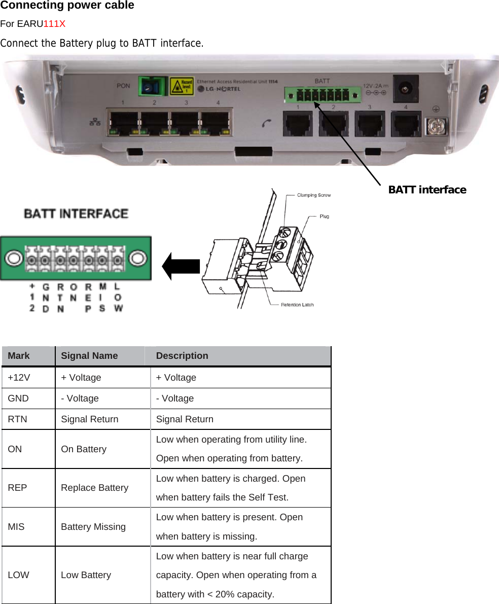
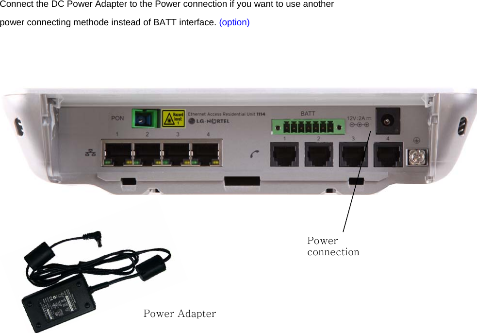
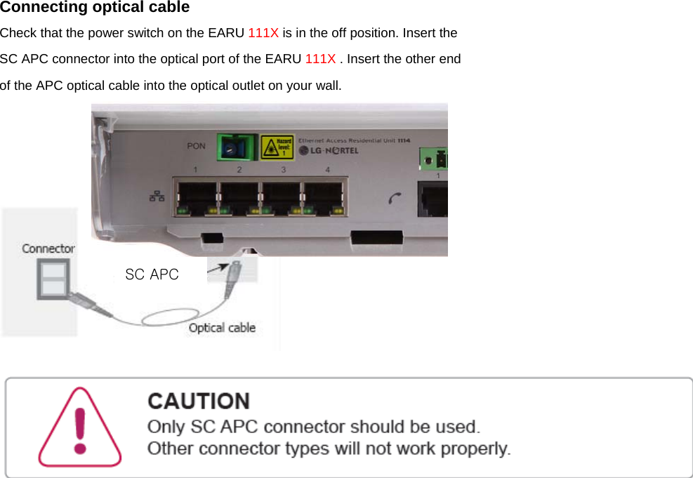
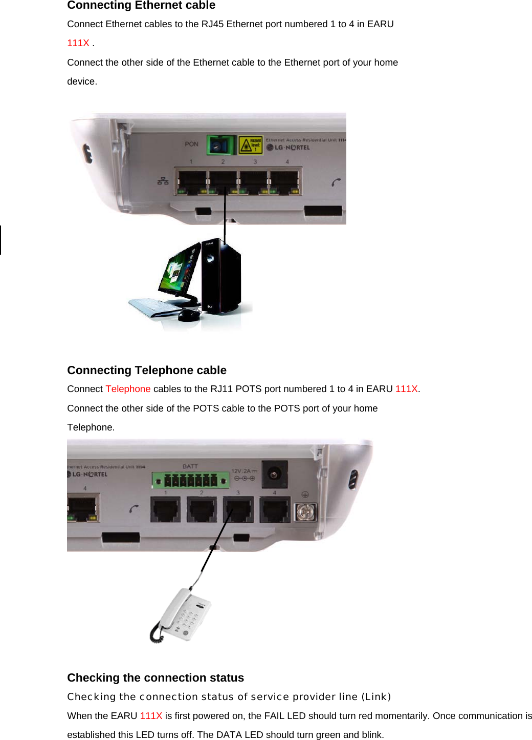
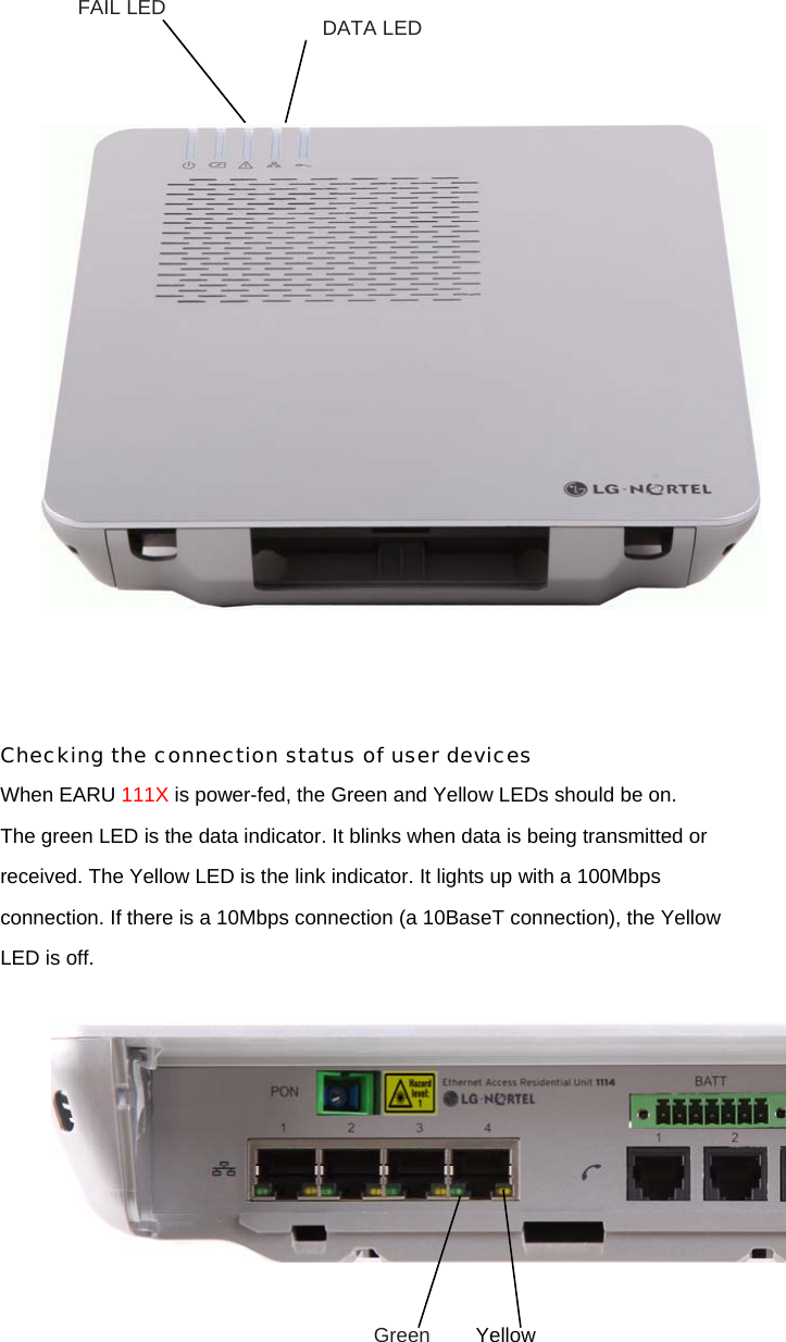
Ericsson LG EARU1114 WDM-PON ONT User Manual EARU 111X 091119

Ericsson-LG Co., Ltd. WDM-PON ONT EARU 111X 091119

User Manual

    Ethernet Access Residential Unit 111X (1113/1113RF/1114)    Please read this manual carefully before operating your set. Retain it for future reference.
C O N T E N T S  3      Product and personal safety guidelines 8      Regulatory information 11      About EARU 111X 16      Checking package contents 17      Installing EARU 111X  24      Setting EARU 111X
Product and personnel safety guidelines This section contains safety guidelines that you must follow for personal safety and to operate the equipment correctly. LG-Nortel documentation contains precautionary messages and safety procedures that refer to specific tasks or conditions. You must read and follow all precautionary messages before you start to work on the equipment. Audience Personnel working directly on equipment must be • trained, authorized, and qualified to carry out the tasks required • able to follow safety guidelines specific to the product and all local customerspecific safety procedures Precautionary messages To prevent personal injury, equipment damage, and service interruptions, you must follow all precautionary messages in LG-Nortel documentation and all local safety standards required by your service provider. The following precautionary messages appear in LG-Nortel documentation:
Safety standards LG-Nortel products conform to all relevant safety standards. The EARU 111X complies with the following safety standards: •IEC/EN 60950-1:2001+A11:2004—Information technology equipment - Safety, Part 1 : General requirements • IEC 60825-1:2001 and IEC 60825-2:2004—Safety of Laser Products • FDA 21 CFR 1040—Performance Standards for Light-Emitting Products Laser radiation—eye safety hazards LG-Nortel optical products use laser or light-emitting diode (LED) sources that emit light energy into optical fibers. This energy is within the red (visible) and infrared (not visible) areas of the electromagnetic spectrum.FDA 21 CFR 1040—Performance Standards for Light-Emitting Products Laser radiation hazards correctly terminated, the optical radiation is completely enclosed. The system is a Class 1(IEC)/Class I (FDA) product, regardless of the power transmitted within the optical fiber. If you have unterminated optical cables (breaks in the fiber-optic cable or disconnected connectors) the output from circuit packs containing optical transmitters does not exceed Class 1 (IEC)/Class I (FDA) and is therefore considered safe under all reasonably foreseeable conditions. The following text includes additional information on the laser for the EARU 111X .  Using optical fibers All activity described herein regarding the optical interface of the EARU 111X is intended only for trained personnel operating under the direction of the service provider. Users and homeowners should not attempt to access or disconnect the optical interface or damage the optical cable. Consult with the service provider before undertaking any action involving the optical interface. Laser wavelength 1530 - 1600 nm Maximum laser output power <= 0.299 mW (-5.25 dBm) Standards: IEC 60825-1:2001 Edition 1.2 FDA 21 CFR 1040.10:2000
Handling optical fibers When you work with optical fibers, you must take the following general precautions: • Wear safety glasses when you install optical fibers.  • Do not look into the opening of an optical fiber, or the opening of an optical fiber connector, if the optical fiber is active or the unit has the power turned on. • Avoid direct exposure to optical fiber ends or optical connector ends where you can access the laser signal directly. • Clean your hands after you handle optical fibers. Small pieces of glass are not always visible and can damage your eyes.  • Do not handle pieces of optical fiber with your fingers. Use tweezers or adhesive tape to lift and discard any loose optical fiber ends. • Wear rubber gloves when you clean optical connectors. The gloves prevent direct contact with the isopropyl alcohol and prevent contamination of the ferrules with skin oils. • Place all optical fiber clippings in a plastic container provided for that purpose. • Handle optical fibers with caution. Place the optical fibers in a safe location during installation. • Protect all optical fiber connectors with clean dust caps at all times. • Follow the manufacturer instructions when you use an optical test set. Incorrect calibration or control settings can create hazardous levels of radiation. Splicing optical fibers When you must look at a spliced optical fiber with a small magnifier, take the following precautions: • Power off all laser sources to the optical fiber or disconnect the remote optical fiber end from the laser sources before you start splicing. Make sure that all laser sources remain disconnected or have the power turned off. • Disconnect all optical test sets from the optical fiber before you start splicing. The connections can be local or remote. • Use only the optical instruments approved by your company.
Repairing optical fibers When an accidental break occurs in the optical fiber, do the following: • Report the location of the damaged optical fiber to both the service provider and the field repair personnel. • Power down all laser sources to the optical fiber or disconnect the remote optical fiber end from the laser sources. Working with power  Other Warnings and cautions WARNINGS
CAUTIONS        Warranty: Customers can receive repair services for this product under specified conditions. This warranty does not cover failure or damage of the product caused from, using a power adapter other than the one provided, PC failures, data loss, or negligent treatment of the product.
Regulatory information This chapter contains the following information: • a list of global technical standards (electromagnetic compatibility, safety) to which the EARU 111X complies • a country-by-country list of specific regulatory text required by national authorities • information on the regulatory labels affixed to the product (artwork and location on the product) The list of global technical standards provided in this chapter is not exhaustive. The standards listed are generally regarded as the primary applicable electromagnetic compatibility (EMC) and safety standards. The conformity status on additional national and international standards not listed in this section can be provided upon request. Compliance to applicable technical standards and regulations The EARU 111X meets or exceeds the following standards and requirements: • (CFR Title 47, Chapter 1) FCC Part 15, Subpart B, Class B (USA) • ICES-003, Issue 4, Class B (Canada) • European Union EMC Directive (2004/108/EC) • European “Low Voltage” Directive (2006/95/EC) • EN 55022:2006 - Class B (European Community, Australia and New Zealand) • EN 55024:1998 +A1:2001 +A2:2003 (European Community) • EN 300 386 V1.3.3 (European Community, Australia and New Zealand) • Australian Radiocommunications Labelling (Electromagnetic Compatibility) Notice 2008 • CAN/CSA-C22.2 No. 60950-1 (Canada) • UL Std No. 60950-1 (USA) • IEC/EN 60950-1:2001+A11:2004 (European Community) • IEC/EN 60825-1:2001 • IEC/EN 60825-2:2004 • AS/NZS 2211.1:2004 (Australia and New Zealand) • AS/NZS 2211.2:2006 (Australia and New Zealand) • Resolution 238:2000 (Brazil) • GB 4943-1995 (China)
Country-specific regulatory information Canada This Class B digital apparatus complies with Canadian ICES-003. Cet appareil numérique de la classe B est conforme à la norme NMB-003 du Canada. United States of America This equipment has been tested and found to comply with the limits for a Class B digital device, pursuant to part 15 of the FCC Rules. These limits are designed to provide reasonable protection against harmful interference in a residential installation. This equipment generates, uses and can radiate radio frequency energy and, if not installed and used in accordance with the instructions, may cause harmful interference to radio communications. However, there is no guarantee that interference will not occur in a particular installation. If this equipment does cause harmful interference to radio or television reception, which can be determined by turning the equipment off and on, the user is encouraged to try to correct the interference by one or more of the following measures: • Reorient or relocate the receiving antenna. • Increase the separation between the equipment and receiver. • Connect the equipment into an outlet on a circuit different from that to which the receiver is connected (consult with the service provider before proceeding). • Consult the service provider or an experienced radio/TV technician for help. Repairs to certified equipment should be coordinated by a representative designated by your service provider. Any repairs or alterations made by the user to this equipment, or equipment malfunctions, may give the service provider cause to request the user to disconnect the equipment. Do not attempt to repair this equipment. If you experience trouble, contact the service provider. European Union The EARU 111X conforms with the essential requirements of Directive 2004/108/ EC (EMC Directive), Directive 2006/95/EC (Low Voltage Directive) and Directive 1999/5/EC (Radio and Telecommunications Terminals Equipment) through compliance to the following harmonized standards: • EN 55022:2006 (Class B) • EN 55024:1998 +A1:2001 +A2:2003 • EN 300 386 V1.3.3 (Class B, other than telecommunications centres criteria) • EN 60950-1:2001 +A11:2004 • EN 60825-1:2001 • EN 60825-2:2004
The product bears the CE mark as illustrated in figures on page14. A signed Declaration of Conformity is available upon request. Brazil The EARU 111X conforms with the requirements of Anatel Resolution Number 442:2006 (EMC) for a Class B product and Anatel Resolution NR 238:2000 for product safety. Japan  (English translation) This is a Class B product based on the standard of the Voluntary Control Council for Interference from Information Technology Equipment (VCCI). If this is used near a radio or television receiver in a domestic environment, it may cause radio interference. Install and use the equipment according to the instruction manual. Australia / New Zealand The EARU 111X complies with EN 55022:2006 (Class B) and EN 300 386 V1.3.3 (Class B) in respect of the EMC regulatory arrangements of the Radiocommunications Act 1992 of the Australian Communications And Media Authority, in particular, the Radiocommunications Labelling (Electromagnetic Compatibility) Notice 2008, and of the New Zealand Ministry of Economic Development. The product bears the C-tick mark as illustrated in figures on page14. A signed Declaration of Conformity is available upon request. Regulatory labels (Safety and EMC) The following labels have been placed on the system and various field replaceable units (FRU). The main product-level regulatory label is located on the rear side of the EARU 111X . See page14. The label bears the product name, power ratings information, certification and other regulatory marks and informational disclosures required by jurisdictional authorities. After reading through this User’s Manual, please keep it handy for easy reference.
About EARU 111X  Thank you for selecting EARU 111X (1113, 1114, 1113RF). The EARU 111X is an equipment working as a modem in WDM-PON (Wavelength Division Multiplexing - Passive Optical Network). This product multiplexes 125Mbps to 100Mbps Fast Ethernet signals (maximum 4ea) into WDM-PON optical signal. This product will allow you to use the different services such as VoD (Video on Demand), EoD (Education on Demand), IP-TV, POTS, RF Overlay and High speed internet access available from your provider.  Names and functions of each part Front view         Body Pedestal ①  ③ ② ④ ⑤
Bottom view EARU 1113   EARU 1114  EARU 1113RF          ⑧ ⑨ ⑩⑫ ⑦⑥  ⑪
LEDs and Port functions   Number  Indicator   Usage  Color  Function  ① PWR Power display  Green ON : Power OK Blink : Firmware Downloading ② FAIL Fail display  Red  ON : Alarm event Blink : Temperature alarm ①+② Combination  Blink (by turns) : CPU booting Blink (at once) : Main application loading Green OFF, Red ON : Boot Fail Green OFF, Red OFF : Check power supply ③  BATT Battery Display Green ON : Battery interface power normal (operate from utility line) OFF : Battery interface power OFF (ONT operate from adaptor line) Blink : Battery pack alarm (batter on, low, missing, fail self test) ④ DATA Data display  Green  ON : Link Blink : activity ⑤  POTS  LOS display  Red  ON : PON LOS Green  ON : Link Blink : activity ⑥ LEDFE (in RJ-45) Ethernet display Yellow ON : 100Base-T OFF : 10Base-T ⑦ BATT Power input - Port for the Battery interface. ⑧  DC 12V, 2A  Power input  -  Port for the DC power adapter.(Option) ⑨ PON Optical cable connection  - This port (optical) should be accessed only by the service provider. It is the access point to the service provider’s network. ⑩  ETH1-4   For connection to Ethernet   -  Ethernet ports that will connect to user devices supporting 10/100 Mbps. ⑪  TEL1-4  For connection to POTS   -  POTS ports that will connect to user devices supporting Telephone. ⑫  CATV  For connection to RF CATV   -  RF ports that will connect to user devices supporting RF CATV.
Labels    Indoor type                             Number item Label Location 1  PEC & SN Label   9.652mm x 27.94mm  Rear 2  CLEI Label 9.652mm x 27.94mm  Rear 3  LGNT Barcode   6.5mm x 35mm  Rear 4 Hazard level 1 (per IEC 60825-2) 9.5mm x 15mm Front 5  Regulatory 17.04mm x 80.44mm  Rear ② ③ ⑤④①
Specifications                 Item   Specification   Dimensions in mm   197.39(w) x 182.4(d) x 40(h)   Power  DC 12V, 2A   Ambient Temperature  0℃ to 50℃(Indoor) Humidity  20% to 80%   Technical standards EN 300 386 (Class B, other then Telecom Centres) FCC part 15 (CFR 47) (Class B) EN 55022 (Class B) / 55024 Data rate  100Mbps   Connectors    SC/APC (optical), RJ45 (Ethernet), RJ11(POTS)   LED indicators  PWR, BATT, FAIL, DATA, POTS
Checking package contents Before installing this product, ensure all parts are provided. Checking what is in the package Check the package to make sure the following items are included. Indoor type (EARU1113, 1114, 1113RF)                              EARU 111X Main body      User manual      Pedestal (for desktop mounting (option))       Wall mouniting kit (Option)     No.  Item Name  Quantity  Item Number 1  WALL MOUNTING PANEL  1  N04697-00 2 SCREW(BN82429-3-8)  4  P04932-00 3 SCREW(BN695-5.5-32)  2  P04714-00 4  SPRIAL PLASTIC PLUG(BN309)  2  P04715-00 5  WALL MOUNTING DRILL TEMPLATE  1  N04698-00
Installing EARU 111X  This section provides the specifications for EARU 111X installation, it also describes how to install it and connect it into a network.  Installation environments  Install the EARU 111X in an environment where the following specifications are met. - Operating temperature: 0℃  to 50℃ - Relative humidity: 20% to 80% - Power consumption: Max 1.4A @12Vdc - Input voltage: 12V 2A  Preparing for installation Before you install the EARU 111X, review following information.                Item   Quantity   Supplied   Main body of EARU 111X 1   yes  DC Battery Interface Connect  1    yes Ethernet (RJ-45), POTS(RJ-11)    as required    no AC/DC Adaptor   1  no  Optical fiber (SC/APC)   1   no
Installing the product  mounting method  Desktop mounting (EARU1113, 1114, 1113RF)                  Step2. Push upper side projections of pedestal toward the upper side holes of main body till they join.      Step1. Insert the lower side projections of the pedestal to the lower side holes of main body. Lower projectionsLower holesUpper holes Upper projections
Wall mounting (EARU1113, 1114, 1113RF) No.  Item Name  Quantity  Item Number 1  WALL MOUNTING PANEL  1  N04697-00 2 SCREW(BN82429-3-8)  4  P04932-00 3 SCREW(BN695-5.5-32)  2  P04714-00 4  SPRIAL PLASTIC PLUG(BN309)  2  P04715-00 5  WALL MOUNTING DRILL TEMPLATE  1  N04698-00 6  EARU 111X BODY  1
 Grounding STEP1: Unfasten the grounding screw on the rear side of the EARU 111X (see following picture) STEP2: Attach the 1-hole lug using the screw that was removed in STEP 1. A1-hole #10 compression with 3.5mm(0.14inch) hole spacing is acceptable for the EARU 111X. The grounding connection is suitable for terminating a #18 AWG wire.             GROUNDING SCREW 1-HOLE LUG
Connecting power cable For EARU111X Connect the Battery plug to BATT interface.                 Mark Signal Name Description   +12V  + Voltage    + Voltage   GND   - Voltage    - Voltage   RTN    Signal Return    Signal Return ON   On Battery  Low when operating from utility line. Open when operating from battery.   REP   Replace Battery  Low when battery is charged. Open when battery fails the Self Test. MIS   Battery Missing  Low when battery is present. Open when battery is missing. LOW Low Battery Low when battery is near full charge capacity. Open when operating from a battery with < 20% capacity. BATT interface
Connect the DC Power Adapter to the Power connection if you want to use another power connecting methode instead of BATT interface. (option)        Power Adapter Power connection
Connecting optical cable Check that the power switch on the EARU 111X is in the off position. Insert the SC APC connector into the optical port of the EARU 111X . Insert the other end of the APC optical cable into the optical outlet on your wall.       SC APC
Connecting Ethernet cable Connect Ethernet cables to the RJ45 Ethernet port numbered 1 to 4 in EARU 111X . Connect the other side of the Ethernet cable to the Ethernet port of your home device.     Connecting Telephone cable Connect Telephone cables to the RJ11 POTS port numbered 1 to 4 in EARU 111X. Connect the other side of the POTS cable to the POTS port of your home Telephone.        Checking the connection status Checking the connection status of service provider line (Link) When the EARU 111X is first powered on, the FAIL LED should turn red momentarily. Once communication is established this LED turns off. The DATA LED should turn green and blink.
        Checking the connection status of user devices When EARU 111X is power-fed, the Green and Yellow LEDs should be on. The green LED is the data indicator. It blinks when data is being transmitted or received. The Yellow LED is the link indicator. It lights up with a 100Mbps connection. If there is a 10Mbps connection (a 10BaseT connection), the Yellow LED is off.       FAIL LED  DATA LED Green  Yellow
Setting EARU 111X When you select to receive WDM-PON service, you do not have to make additional settings on the product to use it. Using Internet With a web browser such as the Internet Explorer on your PC, you can surf freely through the Internet.    Note EARU 111X does not require any access program. Use your regular internet browser.

Navigation menu