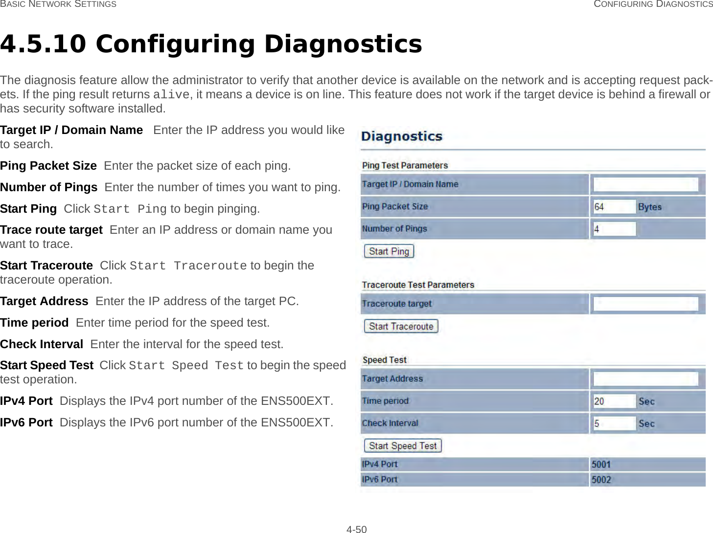
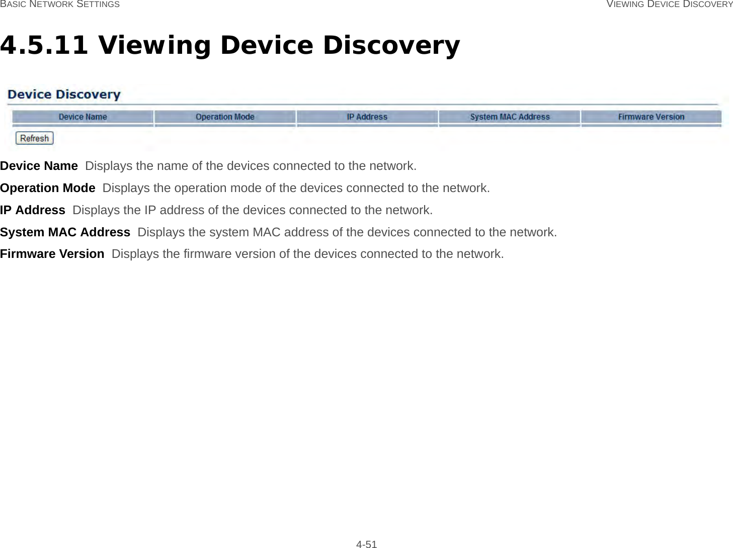
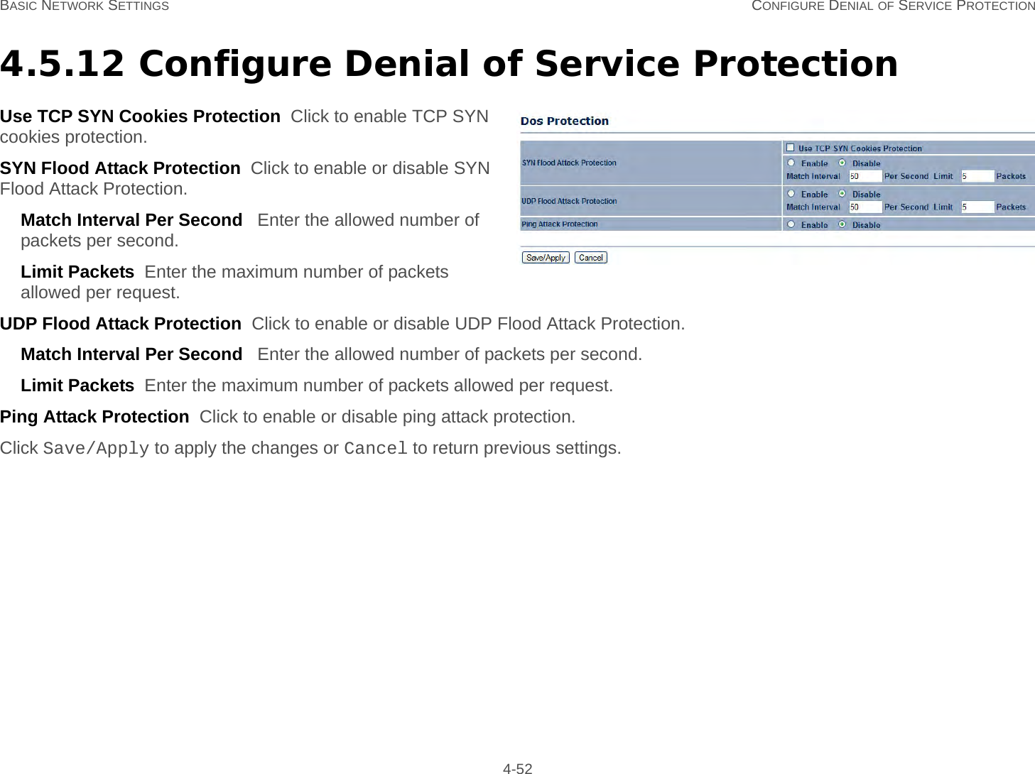
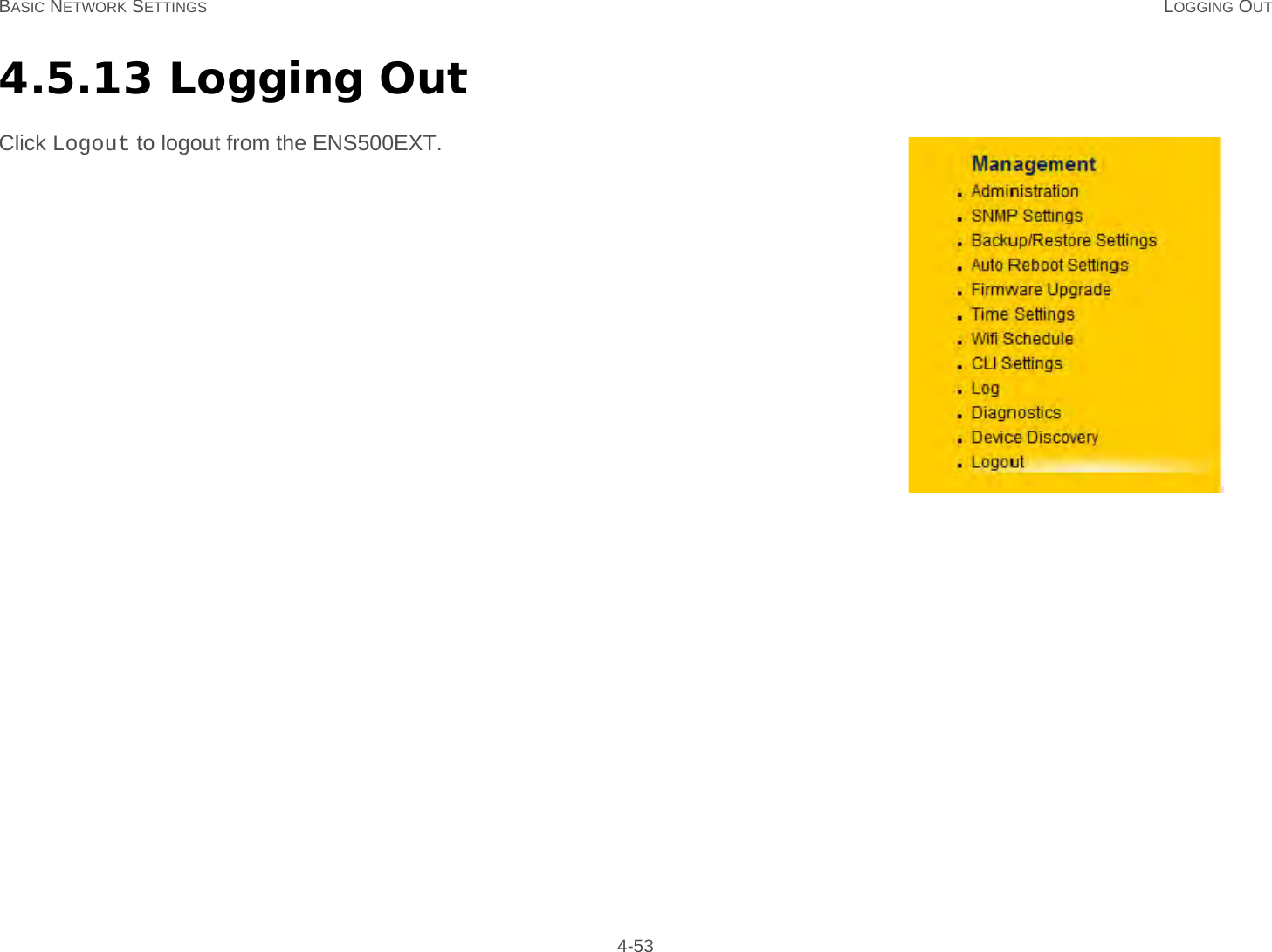
EnGenius Technologies ENS500 LONG RANGE WIRELESS 11N OUTDOOR AP/CB User Manual ENS500EXT

EnGenius Technologies LONG RANGE WIRELESS 11N OUTDOOR AP/CB ENS500EXT

Contents

User Manual Part 2

BASIC NETWORK SETTINGS DYNAMIC IP 4-13Secondary DNS  Enter the secondary DNS server address.Discard Ping on WAN  Check to Enable to recognize pings on the ENS500EXT WAN interface or Disable to block pings on the ENS500EXT WAN interface. Note: Pinging IP addresses is a common method used by hackers to test whether the IP address is valid. Blocking pings provides some extra security from hackers.Click Accept to save the settings or Cancel to discard changes.Dynamic IPDynamic IP addressing assigns a different IP address each time a device connects to an ISP service provider. The service is most commonly used by ISP cable providers.Account Name  Enter the account name provided by your ISP.Domain Name  Enter the domain name provided by your ISP.MTU  The maximum transmission unit (MTU) specifies the largest packet size permitted for an internet transmission. The factory default MTU size for static IP is 1500. The MTU size can be set between 512 and 1500.Get Automatically From ISP  Click the radio button to obtain the DNS automatically from the DHCP server.Use These DNS Servers  Click the radio button to set up the Primary DNS and Secondary DNS servers manually.Discard Ping on WAN  Check to Enable to recognize pings on the ENS500EXT WAN interface or Disable to block pings on the ENS500EXT WAN interface. Note: Pinging IP addresses is a common method used by hackers to test whether the IP address is valid. Blocking pings provides some extra security from hackers.Click Accept to save the settings or Cancel to discard changes.
BASIC NETWORK SETTINGS POINT-TO-POINT PROTOCOL OVER ETHERNET (PPPOE) 4-14Point-to-Point Protocol over Ethernet (PPPoE)Point-to-Point Protocol over Ethernet (PPPoE) is used mainly by ISPs that provide DSL modems to connect to the Internet.MTU  Enter the maximum transmission unit (MTU). The MTU specifies the largest packet size permitted for an internet transmission (PPPoE default: 1492). The MTU size can be set between 512 and 1492.Login  Enter the username assigned by an ISP.Password  Enter the password assigned by an ISP.Service Name  Enter the service name of an ISP (optional).Connect on Demand  Select the radio button to specify the maximum idle time. Internet connection will disconnect when it reach the maximum idle time, but it will automatically connect when user tries to access the network.Keep Alive  Select whether to keep the Internet connection always on, or enter a redial period once the internet lose connection.Get Automatically From ISP  Click the radio button to obtain the DNS automatically from the DHCP server.Use These DNS Servers  Click the radio button to set up the Primary DNS and Secondary DNS servers manually.Discard Ping on WAN  Check to Enable to recognize pings on the ENS500EXT WAN interface or Disable to block pings on the ENS500EXT WAN interface. Note: Pinging IP addresses is a common method used by hackers to test whether the IP address is valid. Blocking pings provides some extra security from hackers.Click Accept to save the settings or Cancel to discard changes.
BASIC NETWORK SETTINGS POINT-TO-POINT TUNNELLING PROTOCOL (PPTP) 4-15Point-to-Point Tunnelling Protocol (PPTP)The point-to-point tunnelling protocol (PPTP) is used in association with virtual private networks (VPNs). There a two parts to a PPTP connection: the WAN interface settings and the PPTP settings.MTU  Enter the maximum transmission unit (MTU). The MTU specifies the largest packet size permitted for an internet transmission (PPPoE default: 1492). The MTU size can be set between 512 and 1492.IP Address  Enter the router’s WAN IP address.Subnet Mask  Enter the router’s WAN subnet IP address.Default Gateway  Enter the router’s WAN gateway IP address.PPTP Server  Enter the IP address of the PPTP server.Username  Enter the username provided by your ISP.Password  Enter the password provided by your ISP.Connect on Demand  If you want the ENS500EXT to end the Internet connection after it has been inactive for a period of time, select this option and enter the number of minutes you want that period of inactivity to last.Keep Alive  If you want the ENS500EXT to periodically check your Internet connection, select this option. Then specify how often you want the ENS500EXT to check the Internet connection. If the connection is down, the ENS500EXT automatically re-establishes your connectionGet Automatically From ISP  Obtains the DNS automatically from DHCP server.
BASIC NETWORK SETTINGS POINT-TO-POINT TUNNELLING PROTOCOL (PPTP) 4-16Use These DNS Servers  Click the radio button to set up the Primary DNS and Secondary DNS servers manually.Discard Ping on WAN  Check to Enable to recognize pings on the ENS500EXT WAN interface or Disable to block pings on the ENS500EXT WAN interface. Note: Pinging IP addresses is a common method used by hackers to test whether the IP address is valid. Blocking pings provides some extra security from hackers.Click Accept to save the settings or Cancel to discard changes.
BASIC NETWORK SETTINGS CONFIGURING LAN SETTINGS 4-174.3.2 Configuring LAN SettingsIP Address  Enter the LAN IP address.IP Subnet Mask  Enter the LAN IP subnet mask.Use Router As DHCP Server  Check this option to enable the ENS500EXT internal DHCP server.Starting IP Address  Specify the starting IP address range for the pool of allocated for private IP addresses. The starting IP address must be on the same subnet as the ending IP address; that is the first three octets specified here must be the same as the first three octets in End IP Address.Ending IP Address  Specify the ending IP address range for the pool of allocated for private IP addresses. The ending IP address must be on the same subnet as the starting IP address; that is the first three octets specified here must be the same as the first three octets in Start IP Address.WINS Server IP  Enter the IP address of the WINS server.Click Accept to confirm the changes or Cancel to cancel and return previous settings.
BASIC NETWORK SETTINGS CONFIGURING VPN PASS-THROUGH 4-184.3.3 Configuring VPN Pass-ThroughVPN Pass-through allows a secure virtual private network (VPN) connection between two computers. Enabling the options on this page opens a VPN port and enables connections to pass through the ENS500EXT without interruption.PPTP Pass-through  Check this option to enable PPTP pass-through mode.L2TP Pass-through  Check this option to enable L2TP pass-through mode.IPSec Pass-through  Check this option to enable IPSec pass-through mode.Click Accept to confirm the changes or Cancel to cancel and return previous settings.
BASIC NETWORK SETTINGS CONFIGURING PORT FORWARDING 4-194.3.4 Configuring Port ForwardingPort forwarding enables multiple server applications on a LAN to serve clients on a WAN over a single WAN IP address. The router accepts incoming client packets, filters them based on the destination WAN, or public, port and protocol and forwards the packets to the appropriate LAN, or local, port. Unlike the DMZ feature, port forwarding protects LAN devices behind the firewall.NO.  Displays the sequence number of the forwarded port.Name  Displays the name of the forwarded port.Protocol   Displays the protocol to use for mapping from the following: TCP, UDP or Both.Start Port  Displays the LAN port number that WAN client packets will be forward to.End Port  Displays the port number that the WAN client packets are received.Server IP  Displays the IP address of the server for the forwarded port.Enable  Click to enable or disable the forwarded port profile.Modify  Click to modify the forwarded port profile.Delete  Click to delete the forwarded port profile.Click Add Entry to add port forwarding rules.Click Accept to confirm the changes.
BASIC NETWORK SETTINGS CONFIGURING PORT FORWARDING 4-20Service Name  Enter a name for the port forwarding rule.Protocol  Select a protocol for the application: Choices are Both, TCP, and UDP.Starting Port  Enter a starting port number.Ending Port  Enter an ending port number. All ports numbers between the starting and ending ports will forward users to the IP address specified in the IP Address field.IP Address  Enter the IP address of the server computer on the LAN network where users will be redirected.Click Save to apply the changes or Cancel to return previous settings.
BASIC NETWORK SETTINGS CONFIGURING DEMILITARIZED ZONE 4-214.3.5 Configuring Demilitarized ZoneConfiguring a device on the LAN as a demilitarized zone (DMZ) host allows unrestricted two-way Internet access for Internet applica-tions, such as online video games, to run from behind the NAT firewall. The DMZ function allows the router to redirect all packets going to the WAN port IP address to a particular IP address on the LAN. The difference between the virtual server and the DMZ func-tion is that a virtual server redirects a particular service or Internet application, such as FTP, to a particular LAN client or server, whereas a DMZ redirects all packets, regardless of the service, going to the WAN IP address to a particular LAN client or server.DMZ Hosting  Select Enable DMZ to activate DMZ functionality.DMZ Address  Enter an IP address of a device on the LAN.Click Accept to confirm the changes or Cancel to cancel and return previous settings.WARNING!The PC defined as a DMZ host is not protected by the firewall and is vulnerable to malicious network attacks. Do  not store or manage sensitive information on the DMZ host.!
BASIC NETWORK SETTINGS CONFIGURING WIRELESS LAN 4-224.4 Configuring Wireless LAN4.4.1 Configuring Wireless SettingsInstructions on how to configure the wireless and security settings for each of the possible operating modes.Access Point ModeThe ENS500EXT supports Access Point Mode. In this mode, users with a wireless client device within range can connect to the ENS500EXT to access the WLAN.Wireless Mode  Wireless mode supports 802.11a/n mixed modes.Channel HT Mode  The default channel bandwidth is 40 MHz. The larger the channel, the better the transmission quality and speed.Extension Channel  Select upper or lower channel. Your selection may affect the Auto channel function.Channel / Frequency  Select the channel and frequency appropriate for your country’s regulation.Auto  Check this option to enable auto-channel selection.AP Detection  AP Detection can select the best channel to use by scanning nearby areas for Access Points.WARNING!Incorrectly changing these settings may cause the device to stop functioning. Do not modify the settings in this section without a thor-ough understanding of the parameters.!
BASIC NETWORK SETTINGS ACCESS POINT MODE 4-23Current Profile  Configure up to four different SSIDs. If many client devices will be accessing the network, you can arrange the devices into SSID groups. Click Edit to configure the profile and check whether you want to enable extra SSIDs.Click Accept to confirm the changes or Cancel to cancel and return previous settings.SSID  Specify the SSID for the current profile.VLAN ID  Specify the VLAN tag for the current profile.Suppressed SSID  Check this option to hide the SSID from clients. If checked, the SSID will not appear in the site survey.Station Separation  Click the appropriate radio button to allow or prevent communication between client devices.Wireless Security  For details on wireless security settings, see Configuring Wireless Security.Click Save to accept the changes or Cancel to cancel and return previous settings.
BASIC NETWORK SETTINGS CLIENT BRIDGE MODE 4-24Client Bridge ModeClient Bridge Mode lets you connect two LAN segments via a wireless link as though they are on the same physical network. Since the computers are on the same subnet, broadcasts reach all machines. As a result, DHCP information generated by the server reach all client computers as though the clients residing on one physical network.Wireless Mode  Wireless mode supports 802.11a/n mixed modes.SSID  Specify the SSID if known. This field is completed automatically if you select an Access Point in the Site Survey.Site Survey  Scans nearby locations for Access Points. You can select a discovered Access Point to establish a connection.Prefer BSSID  Enter the MAC address if known. If you select an Access Point in the Site Survey, this field is completed automatically.Wireless Security  For details on wireless security settings, see Configuring Wireless Security.Click Accept to confirm the changes or Cancel to cancel and return previous settings.Profiles  If you used the Site Survey, the Web Configurator shows nearby Access Points. To connect to an Access Point, click the Access Point’s BSSID.Click Refresh to scan again.
BASIC NETWORK SETTINGS WDS BRIDGE MODE 4-25WDS Bridge ModeUnlike traditional bridging. WDS Bridge Mode allows you to create large wireless networks by linking several wireless access points with WDS links. WDS is normally used in large, open areas, where pulling wires is cost prohibitive, restricted or physically impossible.Wireless Mode  Wireless mode supports 802.11a/n mixed modes.Channel HT Mode  The default channel bandwidth is 40 MHz. The larger the channel, the better the transmission quality and speed.Extension Channel  Select upper or lower channel. Your selection may affect the Auto channel function.Channel / Frequency  Select the channel and frequency appropriate for your country’s regulation.Click Accept to confirm the changes or Cancel to cancel and return previous settings.
BASIC NETWORK SETTINGS WDS BRIDGE MODE 4-26Security  Select the type of WDS security: None, WEP, or AES.WEP Key  Enter the WEP key.AES Pass phrase  Enter the AES pass phrase.MAC Address  Enter the MAC address of the Access Point to which you want to extend wireless connectivity.Mode  Select Disable or Enable to disable or enable WDS.Click Accept to confirm the changes or Cancel to cancel and return previous settings.
BASIC NETWORK SETTINGS CLIENT ROUTER MODE 4-27Client Router ModeIn Client Router Mode, you can access the Internet wirelessly with the support of a WISP. It also supports VPN pass-through for sen-sitive data secure transmission.Wireless Mode  Wireless mode supports 802.11a/n mixed modes.SSID  Specify the SSID if known. This field is completed automatically if you select an Access Point in the Site Survey.Site Survey  Scans nearby locations for Access Points. You can select a discovered Access Point to establish a connection.Prefer BSSID  Enter the MAC address if known. If you select an Access Point in the Site Survey, this field is completed automatically.Wireless Security  For details on wireless security settings, see Configuring Wireless Security.Click Accept to confirm the changes or Cancel to cancel and return previous settings.Profiles  If you used the Site Survey, the Web Configurator shows nearby Access Points. To connect to an Access Point, click the Access Point’s BSSID.Click Refresh to scan again.
BASIC NETWORK SETTINGS CONFIGURING WIRELESS SECURITY 4-284.4.2 Configuring Wireless SecurityThe Wireless Security Settings section lets you configure the ENS500EXT’s security modes: WEP, WPA-PSK, WPA2-PSK, WPA-PSK Mixed, WPA, WPA2, and WPA Mixed. We strongly recommend you use WPA2-PSK.Wired Equivalent Privacy (WEP)Security Mode  Select WEP from the drop-down list to begin the configuration.Auth Type  Select Open System or Shared.Input Type  Select an input type of Hex or ASCII.Key Length  Level of WEP encryption applied to all WEP keys. Select a 64/128/152-bit password lengths.Default Key  Specify which of the four WEP keys the ENS500EXT uses as its default.Key1 - Key4  Specify a password for the security key index. For security, each typed character is masked by a dot.Click Save to save the changes or Cancel to cancel and return previous settings.
BASIC NETWORK SETTINGS WI-FI PROTECTED ACCESS PRE-SHARED KEY (WPA-PSK) 4-29Wi-Fi Protected Access Pre-Shared Key (WPA-PSK)Security Mode  Select WPA-PSK from the drop-down list to begin the configuration.Encryption  Select Both, TKIP, or AES as the encryption type.Both = uses TKIP and AES.TKIP = automatic encryption with WPA-PSK; requires pass-phrase.AES = automatic encryption with WPA2-PSK; requires passphrase.Passphrase  Specify the security password. For security, each typed character is masked by a dot.Group Key Update Interval  Specify how often, in seconds, the group key changes.Click Save to save the changes or Cancel to cancel and return previous settings.
BASIC NETWORK SETTINGS WI-FI PROTECTED ACCESS 2 PRE-SHARED KEY (WPA2-PSK) 4-30Wi-Fi Protected Access 2 Pre-Shared Key (WPA2-PSK)Security Mode  Select WPA2-PSK from the drop-down list to begin the configuration.Encryption  Select Both, TKIP, or AES as the encryption type.Both = uses TKIP and AES.TKIP = automatic encryption with WPA-PSK; requires pass-phrase.AES = automatic encryption with WPA2-PSK; requires passphrase.Passphrase  Specify the security password. For security, each typed character is masked by a dot.Group Key Update Interval  Specify how often, in seconds, the group key changes.Click Save to save the changes or Cancel to cancel and return previous settings.
BASIC NETWORK SETTINGS WI-FI PROTECTED ACCESS PRE-SHARED KEY (WPA-PSK) MIXED 4-31Wi-Fi Protected Access Pre-Shared Key (WPA-PSK) MixedSecurity Mode  Select WPA2-PSK Mixed from the drop-down list to begin the configuration.Encryption  Select Both, TKIP, or AES as the encryption type.Both = uses TKIP and AES.TKIP = automatic encryption with WPA-PSK; requires pass-phrase.AES = automatic encryption with WPA2-PSK; requires passphrase.Passphrase  Specify the security password. For security, each typed character is masked by a dot.Group Key Update Interval  Specify how often, in seconds, the group key changes.Click Save to save the changes or Cancel to cancel and return previous settings.
BASIC NETWORK SETTINGS WI-FI PROTECTED ACCESS (WPA) 4-32Wi-Fi Protected Access (WPA)Security Mode  Select WPA from the drop-down list to begin the configuration.Encryption  Select Both, TKIP, or AES as the encryption type.Both = uses TKIP and AES.TKIP = automatic encryption with WPA-PSK; requires pass-phrase.AES = automatic encryption with WPA2-PSK; requires passphrase.Radius Server  Specify the IP address of the RADIUS server.Radius Port  Specify the port number that your RADIUS server uses for authentication. Default port is 1812.Radius Secret  Specify RADIUS secret furnished by the RADIUS server.Group Key Update Interval  Specify how often, in seconds, the group key changes.Radius Accounting  Select to enable or disable RADIUS accounting.Radius Accounting Server  Specify the IP address of the RADIUS accounting server.Radius Accounting Port  Specify the port number that your RADIUS accounting server uses for authentication. Default port is 1813.Radius Accounting Secret  Specify RADIUS accounting secret furnished by the RADIUS server.Interem Accounting Interval  Specify the interem accounting interval (60 - 600 seconds).Click Save to save the changes or Cancel to cancel and return previous settings.
BASIC NETWORK SETTINGS WI-FI PROTECTED ACCESS 2 (WPA2) 4-33Wi-Fi Protected Access 2 (WPA2)Security Mode  Select WPA2 from the drop-down list to begin the configuration.Encryption  Select Both, TKIP, or AES as the encryption type.Both = uses TKIP and AES.TKIP = automatic encryption with WPA-PSK; requires pass-phrase.AES = automatic encryption with WPA2-PSK; requires passphrase.Radius Server  Specify the IP address of the RADIUS server.Radius Port  Specify the port number that your RADIUS server uses for authentication. Default port is 1812.Radius Secret  Specify RADIUS secret furnished by the RADIUS server.Group Key Update Interval  Specify how often, in seconds, the group key changes.Radius Accounting  Select to enable or disable RADIUS accounting.Radius Accounting Server  Specify the IP address of the RADIUS accounting server.Radius Accounting Port  Specify the port number that your RADIUS accounting server uses for authentication. Default port is 1813.Radius Accounting Secret  Specify RADIUS accounting secret furnished by the RADIUS server.Interem Accounting Interval  Specify the interem accounting interval (60 - 600 seconds).Click Save to save the changes or Cancel to cancel and return previous settings.
BASIC NETWORK SETTINGS WI-FI PROTECTED ACCESS (WPA) MIXED 4-34Wi-Fi Protected Access (WPA) MixedSecurity Mode  Select WPA Mixed from the drop-down list to begin the configuration.Encryption  Select Both, TKIP, or AES as the encryption type.Both = uses TKIP and AES.TKIP = automatic encryption with WPA-PSK; requires pass-phrase.AES = automatic encryption with WPA2-PSK; requires passphrase.Radius Server  Specify the IP address of the RADIUS server.Radius Port  Specify the port number that your RADIUS server uses for authentication. Default port is 1812.Radius Secret  Specify RADIUS secret furnished by the RADIUS server.Group Key Update Interval  Specify how often, in seconds, the group key changes.Radius Accounting  Select to enable or disable RADIUS accounting.Radius Accounting Server  Specify the IP address of the RADIUS accounting server.Radius Accounting Port  Specify the port number that your RADIUS accounting server uses for authentication. Default port is 1813.Radius Accounting Secret  Specify RADIUS accounting secret furnished by the RADIUS server.Interem Accounting Interval  Specify the interem accounting interval (60 - 600 seconds).Click Save to save the changes or Cancel to cancel and return previous settings.
BASIC NETWORK SETTINGS CONFIGURING WIRELESS MAC FILTER 4-354.4.3 Configuring Wireless MAC FilterWireless MAC Filters are used to allow or deny network access to wireless clients according to their MAC addresses. You can manu-ally add a MAC address to restrict the permission to access ENS500EXT. The default setting is Disable Wireless MAC Filters.ACL Mode  Determines whether network access is granted or denied to clients whose MAC addresses appear in the MAC Address table on this page. Choices are Disable, Deny MAC in the list, or Allow MAC in the list.MAC Address Filter  Enter the MAC address of the device.Click Add to add the MAC address to the MAC Address table.Click Apply to apply the changes.Note:This section applies to Access Point and WDS Access point mode.
BASIC NETWORK SETTINGS CONFIGURING WDS LINK SETTINGS 4-364.4.4 Configuring WDS Link SettingsUsing WDS Link Settings, you can create a wireless backbone link between multiple access points that are part of the same wireless network. This allows a wireless network to be expanded using multiple Access Points without the need for a wired backbone to link them, as is traditionally required.Security  Select the type of WDS security: None, WEP, or AES.WEP Key  Enter the WEP key.AES Passphrase  Enter the AES passphrase.MAC Address  Enter the MAC address of the Access Point to which you want to extend wireless connectivity.Mode  Select Disable or Enable to disable or enable WDS.Click Accept to confirm the changes or Cancel to cancel and return previous settings.Note:You must enter the ENS500EXT’s MAC address in an access point to establish a connection to it. For more information on how to enter a MAC address in the access point, refer to its documentation. Not all access points support this feature.
BASIC NETWORK SETTINGS CONFIGURING WIRELESS ADVANCED SETTINGS 4-38SSID1 to SSID4  Specify the percentage of the wireless traffic that is shaped for a specific SSID.Wi-Fi Multimedia (WMM) ParametersWMM manages the priority of audio, video and voice data over a Wi-Fi network so that data from other applications are less likely to interfere with transmission. The parameters CWmin, CWmax and AIFS together control the priority of the four access categories (AC).AC  Displays the following access categories that WMM prioritizes:AC_VO = voiceAC_VI = videoAC_BE = best effortAC_BK = backgroundCWmin  Displays the minimum size of the contention window.CWmax  Displays the maximum size of the contention window.AIFSN  Displays the arbitration inter frame space value (AIFS).TXOP Limit  Displays the transfer opportunity limit in units of 32 microseconds.Click Accept to confirm the changes or Cancel to cancel and return previous settings.
BASIC NETWORK SETTINGS MANAGEMENT SETUP 4-394.5 Management SetupThe Management section lets you configure administration, management VLAN, SNMP settings, backup/restore settings, firmware upgrade, time settings, and log settings. This chapter describes these settings.4.5.1 Configuring Administrator AccountClick the Administration link under the Management menu to change the user name and password used to log on to the ENS500EXT Web Configurator. The default user name is admin and the default password is admin. Changing these settings protects the ENS500EXT configuration settings from being accessed by unauthorized users.New Name  Enter a new username for logging in to the Web Configurator.New Password  Enter a new password for logging in to the Web ConfiguratorConfirm Password  Re-enter the new password for confirmation.Click Save/Apply to apply the changes or Cancel to return previous settings.Remote Management  Enable or disable remote management.Remote Upgrade  Specify whether the ENS500EXT firmware can be upgraded remotely.Remote Management Port  If remote management is enabled, enter the port number to be used for remote management. For example: If you specify the port number 8080, enter http://<IP address>:8080 to access the ENS500EXT Web Configurator.Click Accept to apply the changes or Cancel to return previous settings.
BASIC NETWORK SETTINGS CONFIGURING MANAGEMENT VLAN 4-404.5.2 Configuring Management VLANClick the Management VLAN link under the Management menu to assign a VLAN tag to the packets. A VLAN is a group of computers on a network whose software has been configured so that they behave as if they were on a separate Local Area Network (LAN). Computers on VLAN do not have to be physically located next to one another on the LANManagement VLAN ID  If your network includes VLANs and if tagged packets need to pass through the Access Point, enter the VLAN ID. Otherwise, click No VLAN tag.Click Accept to confirm the changes or Cancel to cancel and return previous settings.Note:If you reconfigure the Management VLAN ID, you may lose your connection to the ENS500EXT. Verify that the DHCP server supports the reconfigured VLAN ID and then reconnect to the ENS500EXT using the new IP address.
BASIC NETWORK SETTINGS CONFIGURING SNMP 4-414.5.3 Configuring SNMPSNMP is used in network management systems to monitor network-attached devices for conditions that warrant administrative atten-tion.SNMP  Enable or disable the ENS500EXT SNMP function.Contact  Enter the contact details of the device.Location  Enter the location of the device.Community Name (Read Only)  Enter the password for accessing the SNMP community for read-only access.Community Name (Read/Write)  Enter the password for accessing the SNMP community for read and write access.Trap Destination Address  Enter the IP address where SNMP traps are to be sent.Trap Destination Community Name  Enter the password of the SNMP trap community.SNMPv3  Enable or Disable the SNMPv3 feature.User Name  Specify the username for SNMPv3.Auth Protocol  Select the authentication protocol type: MD5 or SHA.Auth Key (8-32 Characters)  Specify the authentication key for authentication.Priv Protocol  Select the privacy protocol type: DES.Priv Key (8-32 Characters)  Specify the privacy key for privacy.
BASIC NETWORK SETTINGS CONFIGURING SNMP 4-42Engine ID  Specify the engine ID for SNMPv3.Click Save/Apply to apply the changes or Cancel to return previous settings.
BASIC NETWORK SETTINGS CONFIGURING BACKUP/RESTORE SETTINGS 4-434.5.4 Configuring Backup/Restore SettingsClick the Backup/Restore Setting link under the Management menu to save the ENS500EXT’s current settings in a file on your local disk or load settings onto the device from a local disk. This feature is particularly convenient administrators who have several ENS500EXT devices that need to be configured with the same settings.This page also lets you return the ENS500EXT to its factory default settings. If you perform this procedure, any changes made to the ENS500EXT default settings will be lost.Save A Copy of Current Settings  Click Backup to save the current configured settings.Restore Saved Settings from A File  To restore settings that have been previously backed up, click Browse, select the file, and click Restore.Revert to Factory Default Settings  Click Factory Default to restore the ENS500EXT to its factory default settings.
BASIC NETWORK SETTINGS CONFIGURING FIRMWARE UPGRADE 4-444.5.5 Configuring Firmware UpgradeFirmware is system software that operates and allows the administrator to interact with the router.To update the firmware version, follow these steps:1. Download the appropriate firmware approved by EnGenius Networks from an approved web site.2. Click Choose File.3. Browse the file system and select the firmware file.4. Click Upload.5. The ENS500EXT restarts automatically after the upgrade completes.WARNING!Upgrading firmware through a wireless connection is not recommended. Firmware upgrading must be performed while connected to an Ethernet (LAN port) with all other clients disconnected.The firmware upgrade procedure can take several minutes. Do not power off the ENS500EXT during the firmware upgrade, as it can cause the device to crash or become unusable.Note:Save the firmware file to a local hard drive.!
BASIC NETWORK SETTINGS CONFIGURING SYSTEM TIME 4-454.5.6 Configuring System TimeChange the system time of the ENS500EXT by manually entering the information, synchronizing the device with a PC, or setup auto-matic updates through a network time (NTP) protocol server.Manually Set Date and Time  Enter the date and time values in the date and time fields or click the Synchronize with PC button to get the date and time values from the administrator’s PC.Automatically Get Date and Time  Select a time zone from the drop-down list and check whether you want to enter the IP address of an NTP server or use the default NTP server.Enable Daylight Saving  Click to enable or disable daylight savings time. Select the start and stop times from the Start Time and Stop Time dropdown lists.Click Save/Apply to apply the changes or Cancel to return previous settings.
BASIC NETWORK SETTINGS CONFIGURING WI-FI SCHEDULE 4-464.5.7 Configuring Wi-Fi ScheduleUse the Wi-Fi schedule function to control the wireless power ON/OFF service that operates on a routine basis.Add a Schedule ServiceCreate a schedule service type and date/time parameters for a specific service.Schedule Name Enter the description of the schedule service.Service Select the type of schedule service, either Wireless Power ON or Wireless Power OFF.Day Select the days of the week to enable the schedule service.Time of Day Set the start time that the service is active.Click Add to append the schedule service to the sched-ule service table, or Cancel to discard changes.
BASIC NETWORK SETTINGS SCHEDULE SERVICES TABLE 4-47Schedule Services TableThe Schedule function relies on the GMT time setting acquired from a network time protocol (NTP) server. For details on how to con-nect the ENS500EXT to an NTP server, see Configuring System Time.Schedule Table Displays a list of scheduled services for the ENS500EXT. The properties of each service displayed are:# Displays the ID number of the service in the table.Name Displays the description of the service.Service Displays the type of service, either Wireless Power ON or Wireless Power OFF.Schedule Displays the schedule information of when the service is active.Select  Select one or more services to edit or delete.Click Delete Selected to delete the selected services or Delete All to delete all services.Click Apply to save the settings or Cancel to discard changes.
BASIC NETWORK SETTINGS CONFIGURING COMMAND LINE INTERFACE 4-484.5.8 Configuring Command Line InterfaceMost users will configure the ENS500EXT through the graphical user interface (GUI). However, for those who prefer an alternative method there is the command line interface (CLI).  The CLI can be access through a command console, modem or Telnet connec-tion.CLI  Select to enable or disable the ability to modify the ENS500EXT via a command line interface (CLI).Click Save/Apply to apply the changes or Cancel to return previous settings.
BASIC NETWORK SETTINGS CONFIGURING LOGGING 4-494.5.9 Configuring LoggingDisplay a list of events that are triggered on the ENS500EXT Ethernet and wireless interfaces. You can consult this log if an unknown error occurs on the system or when a report needs to be sent to the technical support department for debugging purposes.Syslog  Enable or disable the ENS500EXT syslog function.Log Server IP Address  Enter the IP address of the log server.Local Log  Enable or disable the local log service.Click Save/Apply to apply the changes or Cancel to return previous settings.
BASIC NETWORK SETTINGS CONFIGURING DIAGNOSTICS 4-504.5.10 Configuring DiagnosticsThe diagnosis feature allow the administrator to verify that another device is available on the network and is accepting request pack-ets. If the ping result returns alive, it means a device is on line. This feature does not work if the target device is behind a firewall or has security software installed.Target IP / Domain Name   Enter the IP address you would like to search.Ping Packet Size  Enter the packet size of each ping.Number of Pings  Enter the number of times you want to ping.Start Ping  Click Start Ping to begin pinging.Trace route target  Enter an IP address or domain name you want to trace.Start Traceroute  Click Start Traceroute to begin the traceroute operation.Target Address  Enter the IP address of the target PC.Time period  Enter time period for the speed test.Check Interval  Enter the interval for the speed test.Start Speed Test  Click Start Speed Test to begin the speed test operation.IPv4 Port  Displays the IPv4 port number of the ENS500EXT.IPv6 Port  Displays the IPv6 port number of the ENS500EXT.
BASIC NETWORK SETTINGS VIEWING DEVICE DISCOVERY 4-514.5.11 Viewing Device DiscoveryDevice Name  Displays the name of the devices connected to the network.Operation Mode  Displays the operation mode of the devices connected to the network.IP Address  Displays the IP address of the devices connected to the network.System MAC Address  Displays the system MAC address of the devices connected to the network.Firmware Version  Displays the firmware version of the devices connected to the network.
BASIC NETWORK SETTINGS CONFIGURE DENIAL OF SERVICE PROTECTION 4-524.5.12 Configure Denial of Service ProtectionUse TCP SYN Cookies Protection  Click to enable TCP SYN cookies protection.SYN Flood Attack Protection  Click to enable or disable SYN Flood Attack Protection.Match Interval Per Second   Enter the allowed number of packets per second.Limit Packets  Enter the maximum number of packets allowed per request.UDP Flood Attack Protection  Click to enable or disable UDP Flood Attack Protection.Match Interval Per Second   Enter the allowed number of packets per second.Limit Packets  Enter the maximum number of packets allowed per request.Ping Attack Protection  Click to enable or disable ping attack protection.Click Save/Apply to apply the changes or Cancel to return previous settings.
BASIC NETWORK SETTINGS LOGGING OUT 4-534.5.13 Logging OutClick Logout to logout from the ENS500EXT.
APPENDIX A FEDERAL COMMUNICATION COMMISSION INTERFERENCE STATEMENT A-1Appendix AFederal Communication Commission Interference StatementThis equipment has been tested and found to comply with the limits for a Class B digital device, pursuant to Part 15 of the FCC Rules.  These limits are designed to provide reasonable protection against harmful interference in a residential installation.  This equipment generates uses and can radiate radio frequency energy and, if not installed and used in accordance with the instructions, may cause harmful interference to radio communications.  However, there is no guarantee that interference will not occur in a partic-ular installation.  If this equipment does cause harmful interference to radio or television reception, which can be determined by turn-ing the equipment off and on, the user is encouraged to try to correct the interference by one of the following measures:Reorient or relocate the receiving antenna.Increase the separation between the equipment and receiver.Connect the equipment into an outlet on a circuit different from that to which the receiver is connected.Consult the dealer or an experienced radio/TV technician for help.This device complies with Part 15 of the FCC Rules. Operation is subject to the following two conditions: (1) This device may not cause harmful interference, and (2) this device must accept any interference received, including interference that may cause unde-sired operation.FCC Radiation Exposure StatementWARNING!Any changes or modifications not expressly approved by the party responsible for compliance could void the user's authority to oper-ate this equipment.!
APPENDIX B INDUSTRY CANADA STATEMENT B-1Appendix BIndustry Canada StatementThis device complies with RSS-210 of the Industry Canada Rules. Operation is subject to the following two conditions: (1) This device may not cause harmful interference, and (2) this device must accept any interference received, including interference that may cause undesired operation.Ce dispositif est conforme à la norme CNR-210 d'Industrie Canada applicable aux appareils radio exempts de licence. Son fonc-tionnement est sujet aux deux conditions suivantes: (1) le dispositif ne doit pas produire de brouillage préjudiciable, et (2) ce disposi-tif doit accepter tout brouillage reçu, y compris un brouillage susceptible de provoquer un fonctionnement indésirable.Important:Radiation Exposure Statement: This equipment complies with IC radiation exposure limits set forth for an uncontrolled environment. This equipment should be installed and operated with minimum distance 20cm between the radiator & your body.Déclaration d'exposition aux radiations: Cet équipement est conforme aux limites d'exposition aux rayonnements IC établies pour un environnement non contrôlé. Cet équipement doit être installé et utilisé avec un minimum de 20 cm de distance entre la source de rayonnement et votre corps.
APPENDIX C WORLDWIDE TECHNICAL SUPPORT C-1Appendix CWorldWide Technical SupportREGION/COUNTRY OF PURCHASE SERVICE CENTRE SERVICE INFORMATIONCanadaCANADA web site www.engeniuscanada.comemail rma@engeniuscanada.comcontact numbers Toll Free: (+1) 888-397-2788Local: (+1) 905-940-8181hours of operation Monday - Friday9:00AM to 5:30PM EST (GMT-5)USALOS ANGELES, USA web site www.engeniustech.comemail support@engeniustech.comcontact numbers Toll Free: (+1) 888-735-7888Local: (+1) 714-432-8668hours of operation Monday - Friday8:00 AM to 4:30 PM PST (GMT-8)
APPENDIX C WORLDWIDE TECHNICAL SUPPORT C-2Mexico, Central and Southern AmericaMIAMI, USA web site [ES] es.engeniustech.com[PT] pg.engeniustech.comemail miamisupport@engeniustech.comcontact numbersMiami: (+1) 305-887-7378Sao Paulo, Brazil: (+55)11-3957-0303D.F., Mexico:(+52)55-1163-8894 hours of operation Monday - Friday8:00 AM to 5:30PM EST (GMT-5) EuropeNETHERLANDS web site www.engeniusnetworks.euemail support@engeniusnetworks.eucontact numbers (+31) 40-8200-887 hours of operation Monday - Friday9:00 AM - 5:00 PM (GMT+1)AfricaMiddle EastRussiaCIS / Armenia, Azerbaijan, Belarus,Georgia, Kazakhstan, Kyrgyzstan,Moldova, Tajikistan,Turkmenistan, Ukraine,UzbekistanTurkeyAfghanistanPakistanBangladesh, Maldives,Nepal, Bhutan, Sri LankaDUBAI, UAE web site www.engenius-me.comemail support@engenius-me.comcontact numbersToll Free:U.A.E.: 800-EnGenius800-364-364-87General:(+971) 4357-5599hours of operation Sunday - Thursday9:00 AM - 6:00 PM (GMT+4)REGION/COUNTRY OF PURCHASE SERVICE CENTRE SERVICE INFORMATION
APPENDIX C WORLDWIDE TECHNICAL SUPPORT C-3Singapore, Cambodia,Indonesia, Malaysia,Thailand, Philippines,VietnamChina, Hong Kong, KoreaIndiaSouth AfricaOceaniaSINGAPORE web site www.engeniustech.com.sg/e_warranty_formemail techsupport@engeniustech.com.sgcontact numbers Toll Free:Singapore: 1800-364-3648hours of operation Monday - Friday9:00 AM - 6:00 PM (GMT+8)Others TAIWAN, R.O.C. web site www.engeniusnetworks.comemail technology@senao.comNote:* Service hours are based on the local time of the service center.* Please visit the website for the latest information about customer service.REGION/COUNTRY OF PURCHASE SERVICE CENTRE SERVICE INFORMATION

Navigation menu